manuals.online logo
Brands
  1. Home
  2. •
  3. Brands
  4. •
  5. Elkay
  6. •
  7. Water Dispenser
  8. •
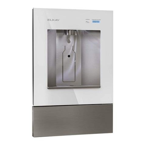
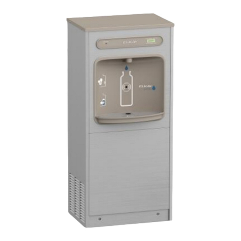
  9. Elkay OBFAVRFR8 1 Series Installation manual

Elkay OBFAVRFR8 1 Series Installation manual

Other Elkay Water Dispenser manuals

Elkay LZWSM8K Installation manual

Elkay

Elkay LZWSM8K Installation manual

Elkay LJNEM102QCDK Installation manual

Elkay

Elkay LJNEM102QCDK Installation manual

Elkay EFW16 2HJO Series Installation manual

Elkay

Elkay EFW16 2HJO Series Installation manual

Elkay LVRCGRNTLD B Series Installation manual

Elkay

Elkay LVRCGRNTLD B Series Installation manual

Elkay EWTLA8K 1L Series Installation manual

Elkay

Elkay EWTLA8K 1L Series Installation manual

Elkay Space-ette FD700-3 1J Series Installation manual

Elkay

Elkay Space-ette FD700-3 1J Series Installation manual

Elkay EBFATL8 1C Series Installation manual

Elkay

Elkay EBFATL8 1C Series Installation manual

Elkay VRCHD8 1A Series Installation manual

Elkay

Elkay VRCHD8 1A Series Installation manual

Elkay VRCGRNTL8 Series Installation manual

Elkay

Elkay VRCGRNTL8 Series Installation manual

Elkay DSBWCT1 Installation manual

Elkay

Elkay DSBWCT1 Installation manual

Elkay FLEXI-GUARD EFRP8C Installation manual

Elkay

Elkay FLEXI-GUARD EFRP8C Installation manual

Elkay VRCTLFR Series Installation manual

Elkay

Elkay VRCTLFR Series Installation manual

Elkay EMABFD B Series Instructions for use

Elkay

Elkay EMABFD B Series Instructions for use

Elkay EFA16 1E Series Installation manual

Elkay

Elkay EFA16 1E Series Installation manual

Elkay EZS8WS 1G Series Instructions for use

Elkay

Elkay EZS8WS 1G Series Instructions for use

Elkay LZO Series Installation manual

Elkay

Elkay LZO Series Installation manual

Elkay EWTLA16*1E Series Installation manual

Elkay

Elkay EWTLA16*1E Series Installation manual

Elkay LVRCGRN8 Series Installation manual

Elkay

Elkay LVRCGRN8 Series Installation manual

Elkay BLUBAR COUNTERTOP DSBCF180K Manual

Elkay

Elkay BLUBAR COUNTERTOP DSBCF180K Manual

Elkay LZWSRK -EZH2O Installation manual

Elkay

Elkay LZWSRK -EZH2O Installation manual

Elkay LFAEH8F 2LJO CCC Series Installation manual

Elkay

Elkay LFAEH8F 2LJO CCC Series Installation manual

Elkay LZOTL Series Installation manual

Elkay

Elkay LZOTL Series Installation manual

Elkay EFW Series Installation manual

Elkay

Elkay EFW Series Installation manual

Elkay VRCTLR8 1D Series Installation manual

Elkay

Elkay VRCTLR8 1D Series Installation manual

Popular Water Dispenser manuals by other brands

IBC Water AST0715MP-960 Installation & operating instructions

IBC Water

IBC Water AST0715MP-960 Installation & operating instructions

Lancaster Water Treatment X FACTOR LX15 Series Installation, operating and service manual

Lancaster Water Treatment

Lancaster Water Treatment X FACTOR LX15 Series Installation, operating and service manual

Oasis Osmosis Home installation manual

Oasis

Oasis Osmosis Home installation manual

Monarch Water ULTIMATE MINI AQUA HE install guide

Monarch Water

Monarch Water ULTIMATE MINI AQUA HE install guide

Haier HLM-109B instruction manual

Haier

Haier HLM-109B instruction manual

GE GXOF18G Owner's manual and installation instructions

GE

GE GXOF18G Owner's manual and installation instructions

Kenmore 625.385560 UltraFilter 650 owner's manual

Kenmore

Kenmore 625.385560 UltraFilter 650 owner's manual

Aries Hydra DI Operation & maintenance manual

Aries

Aries Hydra DI Operation & maintenance manual

Avanti WD31EC instruction manual

Avanti

Avanti WD31EC instruction manual

GE GNCF02H owner's manual

GE

GE GNCF02H owner's manual

Avanti WD360 instruction manual

Avanti

Avanti WD360 instruction manual

ProFlo PFB Series Installation & operation manual

ProFlo

ProFlo PFB Series Installation & operation manual

Frakco Travelsoft RV 2400HD Operation instructions

Frakco

Frakco Travelsoft RV 2400HD Operation instructions

Aqua Essentials Borg & Overström B4 user guide

Aqua Essentials

Aqua Essentials Borg & Overström B4 user guide

KENT 11063 Instruction handbook

KENT

KENT 11063 Instruction handbook

Calmat Plus user manual

Calmat

Calmat Plus user manual

Igloo MWC529 instruction manual

Igloo

Igloo MWC529 instruction manual

Electrolux EQALF01TXSP user manual

Electrolux

Electrolux EQALF01TXSP user manual

manuals.online logo
manuals.online logoBrands
  • About & Mission
  • Contact us
  • Privacy Policy
  • Terms and Conditions

Copyright 2025 Manuals.Online. All Rights Reserved.

97468C (Rev. C - 11/00)
OBFAVRFR8*1
Page 1
Installation, Care & Use Manual
Uses HFC-134A Refrigerant
27
5
SEE FIG. 3
26
719
20, 21,
22, 23
24
26
50
28
43 49
42
18
46
8, 45
54
6
10 35,36,
48
51 31, 32,
33
34 56 10
25
29
30
55
41, 44
38, 39, 40
37
FIG. 1
OBFAVRFR8*1
Page 2
97468C (Rev. C - 11/00)
FIG. 2
*ADA REQUIREMENT
*REQUISITO DE A.D.A.
*EXIGENCE ADA
1/4" (6mm) DIA (6 HOLES)
1/4" (6mm) DIAM. (6 TROUS)
6 AGUJEROS DE 1/4" DE DIÁMETRO
FINISHED FLOOR
PISO ACABADO
PLANCHER FINI
LEGEND/LEYENDA/LÉGENDE
A = RECOMMENDED WATER SUPPLY LOCATION 3/8 O.D. UNPLATED COPPER TUBE CONNECT STUB 1-1/2 IN. (38mm) OUT FROM WALL SHUT OFF BY OTHERS
SE RECOMIENDA UBICAR EL TUBO CORTO DE CONEXIÓN AL TUBO DE COBRE SIN CHAPAR DE 3/8" DE DIÁM. EXT. A1-1/2" (38mm) FUERA DE LA LLAVE DE PASO EN LAPARED COLOCADA POR TERCEROS.
EMPLACEMENT RECOMMANDÉ D'ALIMENTATION EN EAU PAR TUBE EN CUIVRE NON PLAQUÉ DE 3/8 PO. (9,5 mm) D.E. CONNECTANT UNE TUYAUTERIE DE 1-1/2 PO. (38mm) DEPUIS LE ROBINET D'ARRÊT FOURNI PAR D'AUTRES.
B = RECOMMENDED LOCATION FOR WASTE OUTLET 1-1/4 O.D. DRAIN
UBICACIÓN RECOMENDADA PARAEL DRENAJE DE SALIDADEAGUA, DE 1¼ DE DIÁMETRO.
EMPLACEMENT RECOMMANDÉ POUR LE DRAIN DE D.E. 1-1/4" DE SORTIE DEAU.
C = 1-1/4 TRAP NOT FURNISHED**
PURGADOR DE 1¼ NO PROPORCIONADO**
SIPHON 1-1/4 NON FOURNI**
D = ELECTRICAL SUPPLY (3) WIRE RECESSED BOX
CAJA RECESIVA DE ALAMBRES (3) DE SUMINISTRO ELÉCTRICO
BOÎTE ENCASTRÉE DALIMENTATION ÉLECTRIQUE (3) FILS
E = INSURE PROPER VENTILATION BY MAINTAINING 6" (152 mm) (MIN.) CLEARANCE FROM CABINET LOUVERS TO WALL.
ASEGURE UNA VENTILACIÓN ADECUADA MANTENIENDO UN ESPACIO E 6" (152 mm) (MÍN.) DE HOLGURA ENTRE LAREJILLA DE VENTILACIÓN DEL MUEBLE Y LA PARED
ASSUREZ-VOUS UNE BONNE VENTILATION EN GARDANT 6" (152 mm) (MIN.) ENTRE LES ÉVENTS DE LENCEINTE ET LE MUR.
F = 7/16 BOLT HOLES FOR FASTENING UNIT TO WALL
AGUJEROS DE LAS TUERCAS DE 7/16 PARA SUJETAR LAUNIDAD ALAPARED
TROUS DÉCROUS 7/16 POUR FIXER LAPPAREILAU MUR
RIM HEIGHT
ALTURADE LA
CORONA
HAUTEUR DU
BORD
ORIFICE
HEIGHT
ALTURADEL
ORIFICIO
HAUTEUR DE
L'ORIFICE
97468C (Rev. C - 11/00)
OBFAVRFR8*1
Page 3
IMPORTANT
ALL SERVICE TO BE PERFORMED BY AN AUTHORIZED SERVICE PERSON
HANGER BRACKETS AND TRAP INSTALLATION
1) Remove hanger bracket fastened to back of cooler by removing one screw.
2) Mount the hanger bracket and trap as shown in Figure 2.
NOTE: Hanger Bracket MUST be supported securely. Add fixture support carrier if wall will not provide adequate support.
IMPORTANT:
7-3/4 in. (197mm) dimension from wall to centerline of trap must be maintained for proper fit.
Anchor hanger securely to wall using all six 1/4 in. dia. mounting holes.
3) Install straight valve for 3/8" O.D. tube.
INSTALLATION OF COOLER
4) Hang the cooler on the hanger bracket. Be certain the hanger bracket is engaged properly in the slots on the cooler back.
5) Loosen the two screws holding the lower front panel at the bottom of cooler base. Pull front panel forward to gain access inside cooler.
6) Connect water inlet line - See Note 4 of General Instructions.
7) Remove the slip nut and gasket from the trap and install them on the cooler water line making sure that the end of the waste line fits into
the trap. Assemble the slip nut and gasket to the trap and tighten securely.
START UP
Also See General Instructions
8) Stream height is factory set at 35 PSI. If supply pressure varies greatly from this, remove item 2 and adjust screw on item 13. Clockwise
adjustment will raise stream and counter-clockwise adjustment will lower stream. For best adjustment, stream should hit basin
approximately 6-1/2" (165mm) from bubbler.
PROTECT FROM HARD FREEZING
9) If the ambient air temperature drops below 0° F, the cooler needs to be drained of all water by blowing out all water lines, evaporator
(item 46), and the drain trap.
3
2
11
52
57
10
9
14
15
47
11
53
16
17
1
WATER FLOW DIRECTION
4
FIG. 3
OBFAVRFR8*1
Page 4
97468C (Rev. C - 11/00)
ELKAY MANUFACTURING COMPANY  2222 CAMDEN COURT  OAK BROOK, IL 60523  630.574.8484
PRINTED IN U.S.A.
IMPRESO EN LOS E.E.U.U.
IMPRIMÉ AUX É.-U.
PARTS LIST
PART NO
22897C
45662C
70022C
45663C
35906C
35907C
35909C
27124C
56033C
75500C
70864C
27469C
75566C
40045C
15005C
61313C
50986C
75532C
35900C
30699C
70018C
31490C
70009C
22899C
38417001
75524C
55996C
45392C
62152C
66202C
101516143550
100806740570
19037000
35960C
35959C
35768C
66576C
40614C
50400C
50401C
70444C
21903C
27306C
70016C
31513C
66534C
55931C
35958C
15009C
56092C
26999C
22814C
22822C
22854C
22862C
22955C
27295C
400660943730
75519C
75520C
Panel - Bottom Dispenser
Button - Push
Screw - Set
Sleeve - Push Button
Heater Strip
Switch - Rocker
Heater Thermostat Assy
Cover - Cold Control
Washer
Screw - Torx
Screw - #8 x 5/8 Lg. Torx/Slot
Panel - Screen
Screw - Torx
Hex Nut
Retaining - Nut
Regulator
Holder - Regulator
Screw
Power Cord
Fan Blade
Hex Nut - Fan Blade
Fan Motor
Screw - (Fan Motor)
Shroud - Fan
Screw - #8-18 x 3/8 HHSM
Clip (Front and Rear Panels)
Strainer
Bubbler
Condenser
Drier
Stud - Compressor Mtg.
Grommet - Compressor Mtg.
Clip - Compressor Mtg.
Compressor Serv. Pak EM65
Relay
Cover - Relay
Heat Exchanger
Drain Tube
Gasket - Drain
Ring Support - Drain
Clamp - Drain Gasket
Basin - Stainless Steel
Adaptor - Basin
Hex Nut #10-32
Cold Control
Evaporator Assembly
Cover-Dispenser Bottom Gray
Overload
Bubbler - Nipple
Poly Tubing 48" (Cut To Length)
Cover - Bottom
Panel - LH No Push
Panel - RH No Push
Panel - LH Rear
Panel - RH Rear
Panel - Front Lower
Panel - Front Dispenser
Hanger Bracket
Bit - Pinned Torx T-15
Bit - Pinned Torx T-25
ITEM
NO DESCRIPTION
1
2
3
4
5
6
7
8
9
10
11
12
13
14
15
16
17
18
19
20
21
22
23
24
25
26
27
28
29
30
31
32
33
*34
35
36
37
38
39
40
41
42
43
44
45
46
47
48
49
50
51
52
53
54
55
56
57
NS
NS
NS
*REPLACE WITH SAME COMPRESSOR USED IN ORIGI-
NAL ASSEMBLY.
NOTE: All correspondence pertaining to any of the above
water coolers or orders for repair parts MUST include Model
No. and Serial No. of cooler, name and part number of re-
placement part.
FOR PARTS, CONTACT YOUR LOCAL DISTRIBUTOR OR CALL 1.800.323.0620
PARA PIEZAS, CONTACTE ASU DISTRIBUIDOR LOCALO LLAME AL 1.800.323.0620
POUR OBTENIR DES PIÈCES, CONTACTEZ VOTRE DISTRIBUTEUR LOCAL OU COMPOSEZ LE 1.800.323.0620
WARNING!
This unit is frost resistant down to 0° F with no wind. Prevail-
ing winds can reduce the ability of the heater element to
prevent light freezing. If the ambient air temperature will drop
below 0° F, the cooler needs to be drained of all water by
blowing out all water lines, evaporator (item 49), and the
drain trap. A heater strip is used to heat the unit and will
begin to cycle at 40° +/- 5° F. A check at this temperature
will ensure the heater is working and the unit is resistant to
light freezing.
ALSO, MAKE SURE THERE ARE NO PLASTIC OR
FLAMMABLE COMPONENTS DIRECTLY ABOVE THE
HEATER STRIP.
FIG. 5
13
13
12
FIG. 4