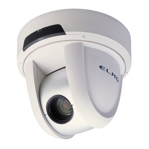
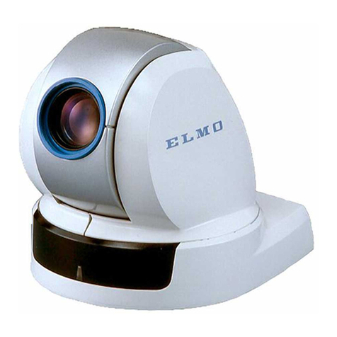
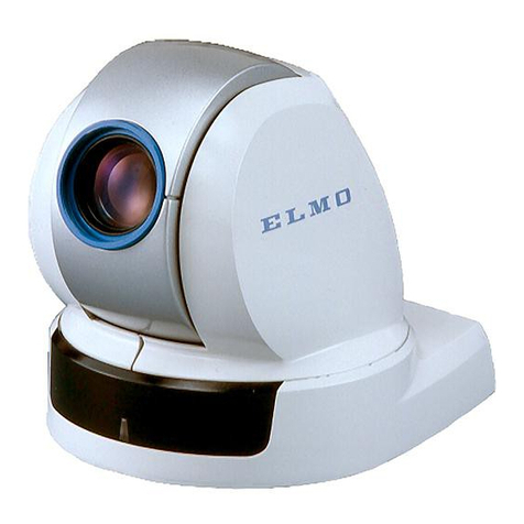
Elmo PTC-401CIP User manual

Please read this instruction manual carefully before using PTC-401C IP and
keep it for future reference.
PAN • TILT • ZOOM COLOR CAMERA
PTC-401C IP
INSTRUCTION MANUAL

1. Read these instructions.
2. Keep these instructions.
3. Heed all warnings.
4. Follow all instructions.
5. Do not use this apparatus outdoors.
6. Do not use this apparatus near water.
7. Clean only with dry cloth.
8. Do not install near heat sources such as radiators, heat registers,
stoves or other apparatus (including amplifiers) that produce heat.
9. Do not touch this apparatus during lightning storms.
10.Unplug when unused for long periods of time.
11.Refer all servicing to qualified personnel. Servicing is required when the
apparatus has been damaged in any way, such as power-supply cord
or plug is damaged, liquid has been spilled or objects have been fallen
onto the apparatus, the apparatus has been exposed to rain or
moisture, does not operate normally, or has been dropped.
- 1 -
WARNING:Handling the cord on this product or cords
associated with accessories sold with this
product, will expose you to lead, a chemical
known to the State of California to cause birth
defects or other reproductive harm.
Wash hands after handling.
IMPORTANT SAFETY INSTRUCTIONS

- 2 -
CAUTION
•Do not use any power supply other
than specified.
WARNING
TO REDUCE THE RISK OF FIRE OR
ELECTRIC SHOCK, DO NOT
EXPOSE THIS APPLIANCE TO RAIN
OR MOISTURE.
* The CAUTION label is attached on
the base of product.
INFORMATION
This equipment has been tested
and found to comply with the
limits for Class B digital device,
pursuant to Part 15 of the FCC
Rules. These limits are designed
to provide reasonable protection
against harmful interference
when the equipment is operated
in a commercial environment.
This equipment generates, use,
and can radiate radio frequency
energy and, if not installed and
used in accordance with the
instruction manual, may cause
harmful interference to radio
communications. Operation of
this equipment in a residential
area is likely to cause harmful
interference in which case the
user will be required to correct
the interference at his own
expense.
USER-INSTALLER
CAUTION: Your authority to
operate this FCC verified
equipment could be voided if you
make changes or modifications
not expressly approved by the
party responsible for compliance
to Part of the FCC Rules.
CAUTION
CAUTION : TO REDUCE THE RISK OF
ELECTRIC SHOCK.
DO NOT REMOVE COVER (OR BACK).
NO USER SERVICEABLE PARTS INSIDE.
REFER SERVICING TO QUALIFIED
SERVICE PERSONNEL.
RISK OF ELECTRIC
SHOCK DO NOT OPEN
The lightning flash with arrowhead
symbol, within an equilateral
triangle, is intended to alert the
user to the presence of
uninsulated "dangerous voltage"
within the product's enclosure that
may be of sufficient magnitude to
constitute a risk of electric shock
to persons.
The exclamation point within an
equilateral triangle is intended to
alert the user to the presence of
important operating and
maintenance (servicing)
instructions in the literature
accompanying the appliance.

■Do not use any AC adapter other than the one supplied with the product.
■This Camera has no power switch. Before maintenance, disconnect the
power plug from the outlet.
■This Camera is designed only for use indoors. Do not use this Camera
out of doors.
■Do not leave the Camera under direct sunlight or by heater, or the
Camera may be discolored, or damaged.
■Do not place the Camera in any humid, dusty, windy or vibrating
location. Use the Camera in the following environmental condition:
Temperature: (Recommended) -10°C to 40°C
(Working) -10°C to 50°C
Humidity: 30% ~ 90% (Non condensing)
■Use a soft, dry cloth for cleaning. Do not use any volatile solvent, such
as thinner or benzin.
■Do not directly point the camera lens into the sun, or the camera may be
damaged.
■This Camera is designed only for installation to the ceiling.
When installing this Camera, use only the dedicated fixing plate, refer to
the pages 11 to 15 of this manual, and carefully check the safety, such
as falling prevention.
■Exclusions
•We will not be liable for any damage arising out of or resulting from acts of
God (including earthquakes, floods, and lightning), fires, accidents, conducts
or other accidents by third parties, or your misuse, whether intentional or
unintentional, or use of the product under undesired conditions.
•We will not be liable for any incidental damage to the use of the product
(including loss of business profit, interruption of business, and change or loss
of records).
•We will not be liable for any damage arising out of or resulting from failure to
observe the instructions stated in the operation manual for the product.
- 3 -
HANDLING PRECAUTIONS

- 4 -
•We will not be liable for any damage arising out of or resulting from
malfunction or hung-up of the product due to the use of an appliance or
software we are not involved in for the product.
•We will not be liable for any damage arising out of or resulting from repairs or
tampering of the product by yourself or any unauthorized third party.
•Our monetary liability shall not exceed the unit price of the product in any
case within the scope provided by laws.
■Precautions about copyrights and rights of portraits
Please keep the following in mind:
•You may infringe the copyrights, rights of portraits or any other rights to
images you record using the product if you use such images in any way
(including distribution, disclosure, and exhibition thereof) without the right
holders’prior consent.
•The filming of demonstrations, performances, exhibits, etc. may be restricted
even for the purpose of monitoring.
•All copyrighted images and data may be used within the scope permitted by
the Copyright Law.
■Precautions about the replacement of the battery for the wireless remote
controller:
•If the Camera is not used for long time, take out the batteries from the case.
•Do not use rechargeable Ni-Cd batteries.
•Do not use new and old batteries, or batteries of different type together.
•Do not try to recharge or short-circuit the batteries.
■Longevity of parts
•The product uses some life-limited parts that must be replaced periodically
(aluminum electrolytic capacitor, backup battery, etc.).
•The service life of each part depends on the working environment or
conditions, and we recommend that you periodical inspections be performed.
Before performing inspections, consult the shop or our nearby branch or
sales office.

- 5 -
CONTENTS
IMPORTANT SAFETY INSTRUCTIONS ...........................................................1
HANDLING PRECAUTIONS ..............................................................................3
CONTENTS ........................................................................................................5
1. PART NAMES AND FUNCTIONS .................................................................7
2. WIRELESS REMOTE CONTROLLER ...........................................................9
3. SETTING UP ................................................................................................11
[1] Installation .........................................................................................................11
[2] Drawing the Composite Cable from the Camera Back Face ............................14
4. OPERATION PROCEDURES ......................................................................16
[1] Power ON/OFF .................................................................................................16
[2] Turning ON/OFF of the Camera power .............................................................16
[3] PAN/TILT operation ..........................................................................................17
[4] Lens operation ..................................................................................................17
[5] Preset operation ................................................................................................19
5. THE ID NUMBER (REMOTE ID) SETTING .................................................20
6. SETTING IN THE OSD (ON-SCREEN DISPLAY) MENU ...........................21
7. Alarm ............................................................................................................29
8. RS-485 .........................................................................................................30
[1] Setting the terminating resistance .....................................................................30
[2] Setting the ID address .......................................................................................30
9. SOUND ........................................................................................................31
10. SETTING OF VARIOUS MODES ..............................................................32
[1] Initializing the settings .......................................................................................32
[2] Setting the RS-485 terminal resistor .................................................................32
11. NETWORK FUNCTION .............................................................................33
[1] Preparations for connection ..............................................................................33
[2] Install .................................................................................................................36
[3] Web browser .....................................................................................................37
(1) Restrictions ..................................................................................................37
(2) Connection ..................................................................................................38
(3) Live display ..................................................................................................41
(4) Capture display ............................................................................................43
(5) Settings ........................................................................................................44
(6) External GPIO Setup ...................................................................................45
(7) MPEG4 Setup ..............................................................................................46
(8) JPEG Setup .................................................................................................47
(9) Network Setup .............................................................................................48
(10) Alarm Setup ...............................................................................................50
(11) E-mail Setup ..............................................................................................51

- 6 -
(12) FTP Setup .................................................................................................52
(13) User Setup .................................................................................................54
(14) IP filtering Setup ........................................................................................56
(15) Camera Control Setup ...............................................................................57
(16) Camera Settings ........................................................................................58
(17) Camera Settings (AE Settings) ..................................................................58
(18) Camera Settings (Picture Settings) ...........................................................60
(19) Camera Settings (Misc. Settings) ..............................................................63
(20) System Time Setup ...................................................................................64
[4] MPEG4 Viewer software [ELMO 1Channel Viewer] .........................................65
(1) Restrictions ..................................................................................................65
(2) Connection ..................................................................................................65
(3) Live display ..................................................................................................67
(4) Sound ..........................................................................................................69
(5) Settings ........................................................................................................70
(6) MPEG4 Setup ..............................................................................................71
(7) JPEG Setup .................................................................................................72
(8) Network Setup .............................................................................................73
(9) Alarm Setup .................................................................................................75
(10) E-mail Setup ..............................................................................................76
(11) FTP Setup .................................................................................................77
(12) Motion Detection Setup .............................................................................79
(13) User Setup .................................................................................................80
(14) IP filtering Setup ........................................................................................82
(15) Snapshot Setup .........................................................................................83
(16) Color Setup ................................................................................................83
(17) Camera Control Setup ...............................................................................84
(18) External GPIO Setup .................................................................................84
(19) Camera Settings (AE Settings) ..................................................................85
(20) Camera Settings (Picture Settings) ...........................................................85
(21) Camera Settings (Misc. Settings) ..............................................................86
(22) System Time Setup ...................................................................................86
(23) Tools ..........................................................................................................87
(24) Firmware update ........................................................................................88
[5] Set items ............................................................................................................90
12. TROUBLESHOOTING HINTS ..................................................................100
13. SPECIFICATIONS ....................................................................................104
14. SUPPLIED ACCESSORIES......................................................................108
15. OPTIONS ..................................................................................................119
- 7 -
●Main unit
ETHERNET TERMINAL (RJ-45)
LED
BASE
ORNAMENTAL RING
CAMERA HEAD
INFRARED
SENSOR
LENS
VIDEO OUT TERMINAL
(BNC jack)
DC IN
COMPOSITE
CABLE
ALARM IN-OUT TERMINAL (6P connector (Black))
RS-485 TERMINAL (5P connector (White))
AUDIO OUTPUT (Green)
AUDIO INPUT (Blue)
1. PART NAMES AND FUNCTIONS

- 8 -
●Wireless Remote Controller
Button Name Function Ref. Page
1
FOCUS
ZOOM
2
3
4
5
6
7
8
9
10
11
12
13
14
15
16
17
18
POWER To turn ON/OFF the Camera power. P.16
PRESET To register the preset position. P.19
ID To set the ID No. when multiple Cameras are used. P.20
NUMBER To move and register the preset position and set the ID No. P.19
RESET To readjust the position of the Camera head. P.17
AUX Not available. -
NORMAL
To return the iris to the factory setting automatically. P.18
IRIS OPEN To open the iris. P.18
CLOSE To close the iris. P.18
AUTO To adjust the focal point automatically to maintain it in the P.18
"in focus" status.
NEAR To move the focal point near. P.18
FAR To move the focal point far. P.18
TELE To zoom in (TELE) the image. P.17
WIDE To zoom in (WIDE) the image. P.17
DIRECTIONS To change the Camera head direction by operating the P.17, 21
cursor on the OSD.
HOME To move the Camera head direction by operating P.17, 21
the cursor on the OSD.
MENU To turn ON/OFF the OSD display. In the hierarchical menu, P.20, 21
the screen immediately before appears.
CURSOR PAN/TILT
To suspend the menu operation. P.21
PRESET
ID
NUMBER
NORMAL
CURSOR
PAN/TILT
AUTO
TELE
MENU
2POWER
1
RESET
5
OPEN
8
AUX
6
CLOSE
9
FAR
11
NEAR
DIRECTIONS
HOME
12
15
16
WIDE
14
3
4
7
10
13
17
18
Note: The " " and "AUX" buttons are not used for normal operation.

- 9 -
Point the infrared emitter of the wireless remote controller to the infrared sensor located on
the front of the Camera main unit, and press the button of the intended operation.
For the receivable range, refer to the below figures.
●Receivable range
Distance : Within approx. 7m from the infrared sensor front
Angle : Within approx. 60° right and left, approx. 10° above
and approx 30° below from the infrared sensor front
Note: The infrared sensors may receive the infrared rays only within a
narrower receivable range or may not receive them at all depending
on the ambient environment, such as being placed under the sunlight
or near an inverter fluorescent lamp. In such case, relocate the
installation place of the receiving side or block off the sunlight.
7m
60°
60°
Side view Bottom view
7m
10°
30°
●Precaution for the battery
Remove the battery case cover by pressing downward on the [ ] mark part in the
direction as indicated by the arrow.
Install 2 pcs. of batteries (type R03,AAA) into the case in the direction as indicated
there.
Note: Install the batteries with the proper to and to polarity.
Note: For dry cells, be sure to use the size AAA.
Note: Change the batteries at least once a year or when even nesessary.
2. WIRELESS REMOTE CONTROLLER

- 10 -
Note: The batteries supplied with the Camera are only for use in initially
confirming the operation of the Camera.
It is not guaranteed that these batteries will work effectively for the
indicated period.
●When multiple Cameras are operated through the wireless
remote controller
Refer to "5. THE ID NUMBER SETTING" on P. 20.

- 11 -
Note: When carrying the Camera, be sure to hold the base.
Note: Do not turn the Camera head in the PAN-TILT direction by hand, or
the Camera head could be broken.
WARNING:The total mass of the main unit and fixing plate is approx. 1,200g.
Check whether the ceiling to which the Camera is installed is strong
enough to hold the total mass of the main unit and fixing plate.
If not, the Camera could fall, causing injury.
(1) Mounting the Fixing Plate
1.Make mounting holes and a cord hole in the place (ceiling) to which this Camera is
installed.
[1] Installation
85.7mm(3-3/8inch)
85.7mm(3-3/8inch)
ø72 (cord hole)
MOUNTING HOLE (prepared hole)
for FIXING PLATE, 4 locations
FRONT
FIXING SCREW M4 × 40 (supplied),
4PCS
FIXING PLATE (supplied)
2.Lock the fixing plate (supplied) firmly with 4 fixing screws (supplied).
3. SETTING UP

- 12 -
WARNING:Fasten the fixing screws of the fixing plate firmly, or the Camera could
fall, causing injury.
(2) Mounting the Camera to the Fixing Plate
1.Match the [ ] mark on the fixing plate with the [ ] mark on the back face of the
main unit, set the tabs (3 locations) of the back face of the main unit in the mating cuts
(3 locations) of the fixing plate, and turn the main unit clockwise by 25°(Refer to A)
MAIN UNIT MATING CUT,
3 LOCATIONS
MARK
MARK
25°
FRONT FRONT
A-1 A-2
A

- 13 -
CEILING PLATE
CEILING TILE
SAFETY WIRE
LOOPING HOLE
SAFETY WIRE (not supplied)
(3) Mounting the Safety Wires
1.Loop up one end of the Safety Wires through the respective safety wire looping holes
made on the Ceiling Plate, and then loop up the other end of the same around the
beams or anything that is used to mount ceiling tile channel for structure safety.

- 14 -
2.Lock the Camera and the fixing plate with the set screws (supplied).
SET SCREW M3×5,
1 PCE (supplied)
[2] Drawing the Composite Cable from the Camera Back Face
(1) Cut off the blank cover from the back face of the Camera base with pliers or the
like, and draw the composite cable from the back face of the Camera.
BLANK COVER
COMPOSITE
CABLE

- 15 -
●Connection of the Camera
RS-485
(5P connector (white))
To RS-485
CONNECTING UNIT
To MONITOR
VIDEO IN
VIDEO CABLE
(commercial item,
BNC, co-axial)
AC adaptor
(supplied)
VIDEO OUT
AUDIO OUTPUT (Green)
AUDIO INPUT (Blue)
RELAY CABLE
(supplied)
DC IN
Camera main unit
COMPOSITE CABLE
(part of the Camera)
To OUTLET
(AC100 - 240V)
To SENSOR and
EXTERNAL CONTROL
ALARM IN-OUT
TERMINAL
(6P connector (black))
Microphone
LAN CROSS CABLE
(supplied)
PC
POWER
CABLE
(supplied)
Speaker
with amplifier
Brown
Red
Orange
Yellow
Green
1
2
3
4
5
DATA (+) IN
DATA (-) IN
DATA (+) OUT
DATA (-) OUT
GND
Pin No. Terminal Name Cord Color
Blue
Gray
White
Black
Pink
1
3
4
5
6
ALARM IN1
Purple
2GND
ALARM IN2
GND
ALARM OUT
General-purpose
output
Pin No. Terminal Name Cord Color
RS-485 terminal
(5P connector (white)) ALARM IN-OUT terminal
(6P connector (black))
Note: When wiring, note the following:
•For the RS-485 ALARM IN-OUT cable, insulate the bare conductor
part not to be exposed after wiring.
•For the video cable, keep the BNC connector (metal part) away
from any other metal material.

- 16 -
(1) Turning OFF the Camera
•When the Camera is ready for operation
through the wireless remote controller and
POWER button is pressed, the Camera
power is turned OFF. (However, even after
the Camera is turned OFF, power is still being
supplied to the Camera as power supply to the
Camera is not OFF.)
•The image disappears, and the LED on the
Camera lights up in red. Now, no buttons on
the wireless remote controller are functional
other than POWER button and ID
button.
•When the OFF TIME function is ON (refer to
the settings in the OSD (On-Screen Display)
Menu screen on P.22), Camera power is
turned OFF automatically upon the lapse of
the set time.
3
1
1
(2) Turning ON the Camera
•When the Camera is OFF and POWER button is pressed, the Camera power is
turned ON.
•The image appears, and the LED on the Camera goes out. Now, the Camera is ready
for operation of all functions through the wireless remote controller.
•If the ID number is changed, the Camera power may not be turned ON. In such case,
redo the ID number setting, and press POWER button.
1
1
31
[2] Turning ON/OFF of the Camera power
[1] Power ON/OFF
The Camera has no POWER switch. The power supply to the Camera is turned ON
when the power cord and AC adapter are connected to the outlet and the Camera.
Once the Camera is turned ON, it automatically starts initial setting.
4. OPERATION PROCEDURES

- 17 -
•When HOME button is pressed, the Camera turns to the front (and the lens moves
to the WIDE end) according to the factory settings. The home position can be set
freely with the preset No. “0.”(Press PRESET button and then press 0
button.) After setting, when 0button or HOME button is pressed, the home
position is called in. (Refer to P. 19)
•If the Camera direction is changed manually by mistake, press RESET button.
Then, the Camera remembers the last PAN/TILT position in memory.
5
16
4
42
16
[4] Lens operation
(1) Zoom operation
•The object is zoomed in (appears larger in the
screen) when TELE button of ZOOM is
pressed, or zoomed out (appears smaller in the
screen) when WIDE button of ZOOM is
pressed.
•When TELE button or WIDE button
is held down for over one second, the zoom
speed increases.
14
13
14
13
[3] PAN/TILT operation
•While watching the screen, press any of
(UP, DOWN, LEFT, RIGHT)
direction buttons for the desired direction in
which you want to watch the image.
•To change the direction minutely, jog the
direction button. To change the direction
largely, hold down the direction button.
•Two operation modes are available according
to the speed: AUTO mode changing the speed
according to the zoom position, and
MANUAL mode setting the speed manually.
(Refer to the settings in the OSD (On-Screen
Display) Menu screen on P.27)
15
5
16
2
4
15
1413

- 18 -
(2) Focus operation
•When AUTO button of FOCUS is
pressed, the FULL AUTO FOCUS status is
established. However, focusing may be
difficult for such objects as listed below.
Objects with no contrast between light and
shade, such as white walls and night views
Objects reflecting an intensive light
Objects moving fast
Objects with many horizontal stripes, such as
blinds
Objects viewed through a glass pane with
water drops or stains
Objects with vertical fine stripes
•To adjust the focus manually, press
NEAR button or FAR button.
When NEAR button is pressed, the focus
shifts near to you.
When FAR button is pressed, the focus
shifts far away from you.
12
11
12
11
10
(3) Iris
•The iris remains in the AUTO IRIS status (in
the Auto Control mode in which the
brightness remains unchanged even if the
object is changed).
•When OPEN button or CLOSE
button of the iris is pressed, the brightness
changes in the AUTO IRIS status. (The reference
level of the AUTO IRIS changes.)
•OPEN button or CLOSE button
cannot be held down. To operate the iris
continuously, repeat pressing and releasing
the button.
•When NORMAL button is pressed (in the
AUTO IRIS state), the brightness is reset to
the standard level.
7
9
8
9
8
12
11
10
8
9
7

- 19 -
2
4
[5] Preset operation
(1) Registration in the Preset Contents
•Set the Camera head direction, the zoom
position, the focus status and the brightness
level. (To register the [CAMERA2] settings
together, set [MAIN CONTROL] –
[CAMERA2 PRESET] to [ON] in the OSD
menu.)
•When PRESET button is pressed (once),
the LED (light emitting diode) on the main
unit blinks in green (at intervals of 0.2 sec).
To cancel this step, press PRESET button
again.
•Then, input the preset No. within 0 through 16
by pressing corresponding one or two of
the 0through +10 buttons. (+10 button is
used to input numeric of 10 or larger. For
“10,”press +10 button and then 0button.)
•Upon pressing, the LED on the main unit goes
out and the registration of the preset contents
is completed. (The preset contents already
registered, if any, are overwritten.)
•The home position can be registered freely to
any position by using the preset No. “0.”
4
2
2
(2) Execution of the Preset
•When intended one or two of the 0through +10 buttons is pressed, the
Camera head direction, the zoom position, the focus status and the brightness
level are set as per registered. (+10 button is used to input numeric of 10 or
larger. For “10,”press +10 button and then 0button.)
4
The Camera head direction, the zoom position, the focus status and the brightness level can
be registered. In addition to these items, when [MAIN CONTROL] –[CAMERA2
PRESET] is set to [ON] in the OSD menu, the [CAMERA2] settings can also be registered
together (Refer to P. 24). Up to 17 setting can be registered (Nos. 0 –16). Even if the main
unit power is turned OFF, the registered contents are preserved.
Other manuals for PTC-401CIP
1
Table of contents
Other Elmo Security Camera manuals

Elmo
Elmo CCD Color Dome Camera TSN400A User manual

Elmo
Elmo Dome Camera TND4104X User manual

Elmo
Elmo TSE270X User manual

Elmo
Elmo CCD Color Video Camera TNC4604 User manual

Elmo
Elmo PTC-100S User manual

Elmo
Elmo QSN301D User manual

Elmo
Elmo TSE270X User manual

Elmo
Elmo BUTP200 User manual

Elmo
Elmo PTC-400C User manual

Elmo
Elmo GDN-E7342WS User manual

Elmo
Elmo TSN410D User manual

Elmo
Elmo ESD-300DR User manual

Elmo
Elmo PTC-100S User manual

Elmo
Elmo TSN420D User manual

Elmo
Elmo PTC-200C User manual

Elmo
Elmo SE420 User manual

Elmo
Elmo HC7501 User manual

Elmo
Elmo Vandal Resistant Dome Camera TND4204VX User manual

Elmo
Elmo ESD-380 User manual

Elmo
Elmo UN411E User manual