ELMON 41-822 User manual

ELMON rail 41-822 ELMON rail 41-322
Safety relais
Operang Manual (see last page for validity)
ELMON rail 41-822 / ELMON rail 41-322 Safety Relais
English
Page 03-14
U.S. Edion 2017
© ASO GmbH

Übergabedokumenta on / Documenta on / Documenta on de
data on / Documentazione di consegna / Documenta e
Anlagenbeschreibung / Descrip on / Descrip on du système / Descrizione impianto / Beschrijving van de
installa e
Anlagenart / Type of plant / Sorte du système / Tipo d’impianto / Type installa e
Hersteller / Manufacturer / Fabricant / Produ ore / Fabrikant
Seriennummer / Serial number / Numéro de série / Numero di serie / Seriennummer
Datum der Inbetriebnahme / Commissioning date / Date de mise en marche / Data della messa in funzione /
Datum van de ingebruikname
Aufstellort / Site of installa on / Lieu de montage / Luogo d’installazione / Opstellingsplaats
Verwendete Steuerung / Control unit / Commande u lisée / Centralina di comando ado ata /
Gebruikte besturing
Zusatzkomponenten / Addi onal components / Composants supplémentaires / Componen ausiliari /
Bijkomende componenten
Funk onsprüfung / Func onal test / Contrôle de fonc on / Controllo funzionale / Func econtrole
Sicherheitssensoren reagieren auf Betä gung / Safety sensor response to actua on /
Le senseur de sécurité réagit à l’ac onnement / Il sensore di sicurezza reagisce all’azionamento /
Veiligheidssensor reageert op ac vering
Sicherheitssensoren reagieren auf Zuleitungsunterbrechung / Safety sensor response to supply
line interrup on / Le senseur de sécurité réagit à l’interrup on de l’alimenta on / Il sensore di
sicurezza reagisce all’interruzione di collegamento / Veiligheidssensor reageert op onderbreking
van de toevoerleiding
ok
Name der ausführenden Firma / Owner / Nom de la société exécutrice / Nome della di a esecutrice /
Naam van de uitvoerende fi rma
Name des Installateurs / Installer / Nom de l’installateur / Nome dell’installatore / Naam van de installateur
Datum / Date / Date / Data /
Datum Unterschri / Signature / Signature / Firma /
Handtekening
ok
ELMON rail 41-822 / ELMON rail 41-322
Safety relais
3
1. Table of Contents
1. Table of Contents . . . . . . . . . . . . . . . . . . . . . . . . . . . 3
2. General safety regulaons and protecon measures . . . . . . . 4
3. General and funcon descripon . . . . . . . . . . . . . . . . . . 5
4. Intended use . . . . . . . . . . . . . . . . . . . . . . . . . . . . . . 6
5. Applicaon example. . . . . . . . . . . . . . . . . . . . . . . . . . 6
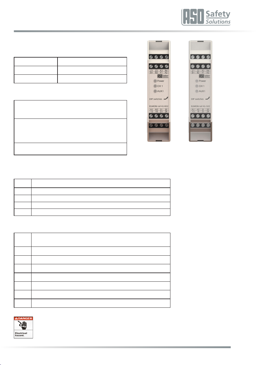
6. Device overview . . . . . . . . . . . . . . . . . . . . . . . . . . . . 7
6.1 Versions . . . . . . . . . . . . . . . . . . . . . . . . . . . . . . . . . . . . . . 7
6.2 Signal indicators . . . . . . . . . . . . . . . . . . . . . . . . . . . . . . . . . . 7
6.3 Connecon terminals . . . . . . . . . . . . . . . . . . . . . . . . . . . . . . . 7
6.4 DIP switch for conguring the operang mode . . . . . . . . . . . . . . . . . 8
7. Operang modes . . . . . . . . . . . . . . . . . . . . . . . . . . . 8
7.1 Safety output . . . . . . . . . . . . . . . . . . . . . . . . . . . . . . . . . . . . 8
7.2 Automac reset . . . . . . . . . . . . . . . . . . . . . . . . . . . . . . . . . . 8
7.3 Fault self-retaining – manual reset . . . . . . . . . . . . . . . . . . . . . . . . 8
7.4 Signaling output without any delay (RLU) . . . . . . . . . . . . . . . . . . . . 8
7.5 Signaling output delayed (RL) . . . . . . . . . . . . . . . . . . . . . . . . . . . 8
8. Mechanical mounng . . . . . . . . . . . . . . . . . . . . . . . . . 9
9. Electrical connecon . . . . . . . . . . . . . . . . . . . . . . . . . 9
9.1 Supply voltage . . . . . . . . . . . . . . . . . . . . . . . . . . . . . . . . . . . 9
9.2 Connecon of sensor . . . . . . . . . . . . . . . . . . . . . . . . . . . . . . . 9
9.3 Connecon of mulple sensors per sensor circuit. . . . . . . . . . . . . . . . 9
9.4 Connecon of control circuits . . . . . . . . . . . . . . . . . . . . . . . . . . 10
9.5 Connecon Reset. . . . . . . . . . . . . . . . . . . . . . . . . . . . . . . . . 10
9.6 Connecon of signaling contact. . . . . . . . . . . . . . . . . . . . . . . . . 10
10. Commissioning and funcon tesng . . . . . . . . . . . . . . . . .11
11. Fault diagnosis . . . . . . . . . . . . . . . . . . . . . . . . . . . . .11
12. Decommissioning and disposal. . . . . . . . . . . . . . . . . . . .11
13. Technical data . . . . . . . . . . . . . . . . . . . . . . . . . . . . .12
14. Warnings and Disclaimers. . . . . . . . . . . . . . . . . . . . . . .13
15. EC Declaraon of Conformity . . . . . . . . . . . . . . . . . . . . .14
4
Safety relais
2. General safety regulaons and protecon measures
• The manufacturer and user of the system/machine on which the protection system is used are
responsible for coordinang and adhering to all applicable safety rules and regulaons under their own
responsibility.
• The protecon system guarantees funconal safety in combinaon with the superordinate control
system, but not the safety of the enre system/machine. Thus, a safety review of the enre system/
machine in accordance with machine direcve 2006/42/EC or relevant product standards is necessary
prior to use of the device.
• The operang instrucons must be permanently available at the operang locaon of the protecon
device. They must be thoroughly read and applied by every person who is tasked with the operaon,
maintenance or repair of the protecon device.
• The installaon and start-up of the protecon device may only be conducted by specialized personnel
who are familiar with these operang instrucons and the applicable regulaons on job safety and
accident prevenon. The instrucons in these operang instrucons must be followed and adhered to
uncondionally.
• Electrical work must only be carried out by skilled electricians. Safety regulaons for electrical engineering
and from the professional associaon must be followed.
• In case work has to be carried out on the switching device, it must be switched to a voltage-free posion
and checked for freedom from any voltage and secured against being switched back on again.
• If the potenal-free connecons of the safety switching contacts are supplied with a hazardous voltage
from an external source, it must be ensured that these are also switched o when working on the
switching device.
• The switching device does not contain any components that the user must service. Any warranty or
liability on the part of the manufacturer is forfeited in the event of any unauthorized modicaons or
repairs to the switching device.
• Auxiliary outputs must not execute any safety-orientated funcons. They are not fail-safe and are not
checked either by tesng.
The system must be checked for correct funcon in suitable intervals by qualied persons for
the standard-conform design of the safety system. The check must be documented in a way that
allows it to be traced at any me.
In the case of non-compliance or deliberate abuse, the manufacturer’s liability will cease.
!
ELMON rail 41-822 / ELMON rail 41-322
Safety relais
5
3. General and funcon descripon
The ELMON rail 41-822 (ELMON rail 41-322) switching device is used to evaluate sensors such as safety
contact mats, safety contact edges and safety bumpers for securing crush and shear locaons.
An ASO sensor can be connected to the switching device. The steady-state current monitoring of the sensor
is made possible by an integrated terminang resistor in the sensor.
Furthermore, the device can also evaluate a sensor in four-wire technology.
If the desired steady-state current ows, the safety relays are driven and the switching contacts closed. If
the sensor is operated or the sensor circuit is interrupted, the relay switching contacts open.
A signal output with potenal-free switching contacts is available. An operaon of the sensor causes a
reacon of the signal output in accordance with the DIP switch conguraon. The signal output must not
execute any safety-orientated funcons. It is not fail-safe and not checked by tesng either.
The switching device has been designed and type-approved in accordance with EN ISO 13849-1 “Safety-
related parts of control systems” for category 3 Performance Level e. For compliance with category 3, the
safety output is set up redundantly with two independent switching elements.
In addion the device has been type-approved according to EN 62061 “Funconal safety of safety-related
electrical, electronic and programmable electronic control systems“ and can meet a safety funcon up to
SIL 3.
The monitoring state of the sensor and the applied operang voltage are indicated by LED.
If there is a fault alarm, all safety outputs are inacve.
Installaon and electrical work must be performed by authorized electricians.
The unit can be used in a household environment as well as an industrial environment up to
an altude of 2000m above mean sea level. The unit must not be operated in areas with major
temperature changes.
!
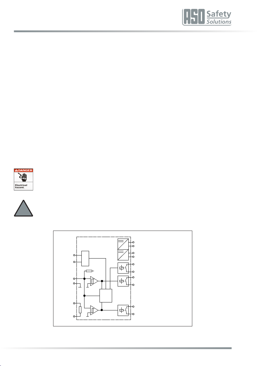
Funconal circuit diagram
Logic
Mode
Reset
R
+U2 AUX1
OUT
REL1
OUT
Reset
Manual Z1
Z2
X1
X2
X3
X4
SIG
A1
A2
B1
B2
31
32
13
14
23
24
24V AC/DC
REL2
OUT
ELMON rail 41-322: 230 V AC
(ELMON rail 41-822: 120 V AC)

6
Safety relais
4. Intended use
The switching device can only fulll its safety-relevant task, if it is used as intended within specicaons.
The intended use of the switching device is the use as a protecon system in connecon with safety contact
mats, safety bumpers and safety contact edges with 8.2 kΩ resistance for steady-state current monitoring.
It is not allowed to use the safety relay in heights over 2000 m above sea level or potenally explosive
atmospheres.
A dierent use or any use going beyond the intended use is not within specicaons. The manufacturer
does not accept any liability for any damage arising from use not within specicaons.
Any use for special applicaons requires prior release by the manufacturer.
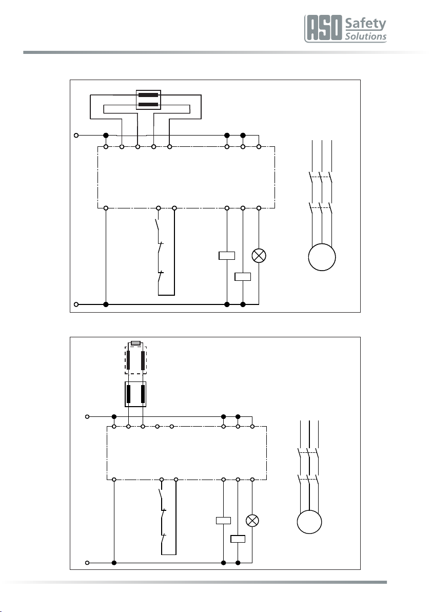
5. Applicaon example
Safety-orientated monitoring of a safety contact edge with start release via release pushbuon and separate
connuaon of the control circuits (category 3 compliant applicaon according to EN ISO 13849-1).
In order to check the funconality of the load breaking K1 and K2 relays the break contacts of these contactors
are integrated into the start circuit (Z1 Z2).
The signaling relay output is used to visualize the switching state of the safety contact strip.
Circuit diagram in voltage-free state. Sensor not operated.
1 Sensor (edge, mat or bumper)
2 Release key
+24V
M
13
14
K2
23
24
33
34
L1 L2 L3
31
8,2 ΚΩ
14
K1
24 34
13 23 33
2313X2X1B1 X4X3
S1
322414B2 Z2Z1
41
41
42
42
K2
K1 X1
Reset
0V
5.1 2-Wire Single Applicaon Example
ELMON rail 41-822 / ELMON rail 41-322
Safety relais
7
5.2 4-Wire Single Applicaon Example
5.3 2-Wire Mulple Applicaon Example
+24V
M
13
14
K2
23
24
33
34
L1 L2 L3
31
8,2 ΚΩ
14
K1
24 34
13 23 33
2313X2X1B1 X4X3
S1
322414B2 Z2Z1
41
41
42
42
K2
K1 X1
Reset
0V
S1
S“n“
8k2 Ω
+24V
M
13
14
K2
23
24
33
34
L1 L2 L3
31
8,2 ΚΩ
14
K1
24 34
13 23 33
2313X2X1B1 X4X3
S1
322414B2 Z2Z1
41
41
42
42
K2
K1 X1
Reset
0V

8
Safety relais
5.4 4-Wire Mulple Applicaon Example
+24V
M
13
14
K2
23
24
33
34
L1 L2 L3
31
8,2 ΚΩ
14
K1
24 34
13 23 33
2313X2X1B1 X4X3
S1
322414B2 Z2Z1
41
41
42
42
K2
K1 X1
Reset
0V
S1 S“n“
ELMON rail 41-822 / ELMON rail 41-322
Safety relais
9
6. Device overview
6.1 Versions
Version Supply voltage
ELMON rail 41-822 120 V 50/60 Hz and 24V AC/DC
ELMON rail 41-322 230 V 50/60 Hz and 24V AC/DC
6.2 Signal indicators
LED Power (green)
Operang state (on)
Fault alarm (pulse)
LED CH 1 (red)
Sensor operated (on)
Sensor power circuit interrupted (fast ashing)
Fault self-retaining (slow ashing)
LED AUX 1 (yellow)
Signal output switched
If there is no fault alarm, then the operang state is shown via the Power LED (on). When a fault alarm is issued,
the number of pulses output indicates the fault:
Pulse Fault alarm
1Voltage supply outside the valid value range
2Fault when tesng signal input
3Output control relay faulty
4Data transmission between micro-controllers faulty
6.3 Connecon terminals
A1 A2 ELMON rail 41-822: Supply voltage 120 V 50/60 Hz
ELMON rail 41-322: Supply voltage 230 V 50/60 Hz
B1 B2 Supply voltage 24 V AC/DC
X1 X2 Connecon sensor
X3 X4 Internal terminang resistor
13 14 Switching contact safety relay 1
23 24 Switching contact safety relay 2
31 32 Switching contact signal relay
Z1 Z2 Connecon manual reset /re-start (key NO; oponal)
Installaon and electrical work must be performed by authorized electricians.
Wrong installaon can cause hazardous condions.
ELMON rail 41-822 ELMON rail 41-322
10
Safety relais
6.4 DIP switch for conguring the operang mode
S1
„ON“: Automac reset
„OFF“: Fault self-retaining – manual reset (factory seng)
S2
„ON“: AUX1 Mode signal output: RLU
„OFF“: AUX1 Mode signal output: RL (factory seng)
7. Operang modes
7.1 Safety output
Separate or series-connected output of the control circuits (redundant connuaon of the switching contacts).
In order to use the two safety relays separately, the bridge between 14 and 23 must be removed.
7.2 Automac reset
(S1 = „ON“)
Aer removing a fault in a sensor circuit or aer a voltage failure, the switching unit will automacally release
output again.
Aenon: Automac restart of mashine! If this seng is used, it has to be ensured that no one
is able to be in the dangerous zone to avoid hazardous situaons. The integrator or operator is
responsible for the correct sengs of the controller. In no case the manufacturer is liable for
incorrect sengs or missuse.
7.3 Fault self-retaining – manual reset
(S1 = „OFF“)
Following removal a fault of in a sensor circuit, or aer a voltage failure, the switching unit will only release
the output(s) again, if the Z1 and Z2 contacts, 500 ms aer the eliminaon of the disrupon, are closed by
means of a pushbuon. This completely prevents any automac re-start. A permanent bridging of the Z1 and
Z2 contacts does not cause an automac reset.
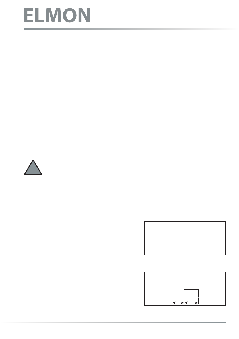
7.4 Signaling output without any delay (RLU)
(S2 = „ON“)
In this mode of operation the corresponding signaling
output is acvated without delay, if any fault is signaled on
the corresponding channel. The output is always inacve
in the de-energized state of the switching device.
7.5 Signaling output delayed (RL)
(S2 = „OFF“)
In this operang mode the corresponding signaling output
is acvated with a delay of 0.5 seconds and then remains
acve for a maximum of 3 seconds, if a fault is signaled.
!
Output
Aux. Relay
Output
Aux. Relay
3s
0,5s
Safety output (symbolic)
Signaling output (symbolic)
Safety output (symbolic)
Signaling output (symbolic)

ELMON rail 41-822 / ELMON rail 41-322
Safety relais
11
8. Mechanical mounng
The switching unit must be mounted correctly:
• In a dust-protected and moisture-protected switch cabinet or casing.
• For use in an environment with level 2 contaminaon.
• With a protecon type of at least IP54.
• On a 35 mm DIN support rail according to EN 50 022.
The switching unit can be installed in any posion.
The unit must not be operated in areas with major temperature changes.
9. Electrical connecon
Installaon and electrical work must be performed by authorized electricians.
The switching unit can be destroyed by connecon to the incorrect terminals.
Lines that are routed in the open air or outside the switch cabinet must be protected accordingly.
The limit values stated in the “Technical Data” for the supply voltage and the switching capability
of the relay must be observed.
9.1 Supply voltage
The supply voltage can oponally be eected by means of a mains voltage of 120 V AC 50/60 Hz
(ELMON rail 41-322: 230 V AC 50/60Hz) or a low voltage of 24 V AC/DC. For a supply with 24 V
AC/DC the voltage must correspond to the requirements for protecve low voltages (SELV). The
supply line to the switching device must be protected by means of a 5x20 glass tube fuse 200mA
medium me lag.
Never apply both voltages simultaneously!
The 120 V (230 V) supply voltage must be applied to the A1 and A2 terminals. For operaon with 24 V, the
supply voltage must be applied to the B1 and B2 terminals.
For a xed installaon a separang device must be available (for example, a main switch for the system). A
mains plug is sucient as a separang device, if it is freely accessible.
9.2 Connecon of sensor
The sensor with a terminang resistor of 8.2 kΩ must be connected to the X1 and X2 terminals.
The sensor without a terminang resistor is connected to the X1 and X2 terminals by means of one lead and
with the other lead to the X3 and X4 terminals.
9.3 Connecon of several sensors per sensor circuit
ASO-Sensors must not be connected in parallel.
One or several sensors can be connected to the signal transmier input. For this purpose, the individual
sensors are connected in series in accordance with Figure 1.
!
!
!
!
To avoid the risk of crushing, Safety gloves must be worn!
Installaon and electrical work must be performed by authorized
electricians.

12
Safety relais
Safety contact edge SENTIR edge:
A maximum of 5 SENTIR edge devices can be connected in series. The maximum total length of the SENTIR
edge must not exceed 100 m.
The length of a SENTIR edge can be up to 25 m.
The total line length of the series-connected SENTIR edge must not exceed 25 m.
Safety contact bumper SENTIR bumper:
A maximum of 5 SENTIR bumper devices can be connected in series. The maximum total length of the SENTIR
bumpers must not exceed 15 m.
The length of a SENTIR bumper may be up to 3 m.
The total line length of the series-connected SENTIR bumpers must not exceed 25 m.
Safety contact mat SENTIR mat:
A maximum of 10 SENTIR mats can be connected in series. The maximum total surface area must not exceed
10 m2.
The size of a SENTIR mat can be up to 1350 x 2350 mm.
The total line length of the series-connected SENTIR mat must not exceed 25 m.
Before connecng the series-connected sensors, it is recommended to measure the resistance value of the
wiring. In the case of non-operated sensors the resistance must be 8.2 kΩ ± 500 Ω. If the sensor is operated,
the resistance must not exceed 500 Ω.
9.4 Connecon of control circuits
Connect the control circuit to be monitored to the 13 and 24 terminals. If the switching contacts are redundantly
connued, the factory-inserted bridge between the 14 and 23 terminals must be removed.
In the event of any redundant use of the switching contacts only voltages with the same potenal
may be connected. The use of dierent voltage potenals does not correspond to any intended
use within specicaons.
Depending on the nominal current, the control circuits are to be protected by a corresponding
fuse, or the nominal current on the control circuits must be limited to the maximum value by
means of other measures.
9.5 Connecon Reset
For the operang mode “manual reset” the necessary reset switch must be connected to the Z1 and Z2
terminals.
9.6 Connecon of signaling contact
The 31 and 32 signaling contact only serves as an auxiliary contact (signaling, display etc.) and must not be
integrated into the safety circuit.
The signaling contact may only switch extra low voltages (24V). The switching of low voltages
120 V (230V) is not permissible.
Installaon and electrical work must be performed by authorized electricians.
Wrong installaoncan cause hazardous condions.
The manufacturers liability will erase in any case of non-compliant or deliberate abuse.
Fig. 1: Interconnecng several sensors, here using the example of the safety contact edge
Sensor 1 Sensor 2 Sensor „n“
O
C
2
222
!
!

ELMON rail 41-822 / ELMON rail 41-322
Safety relais
13
10. Commissioning and funcon tesng
Following a corresponding connecon of all electrical connecons and switching on the supply voltage, the
system / machine must be checked for correct funconality.
Aer successful commissioning the 13 and 24 safety output is driven (relay contact “closed“). An operaon
of the sensor causes an opening of the 13 and 24 relay contact.
The signaling relay (31 32 connecon) switches in accordance with the present DIP switch posion. This is
indicated by means of the yellow AUX1 LED.
The safety system must be inspected by competent specialists at suitable intervals. The check must be
documented in a way that allows it to be traced at any me. The requirements of the system / machine
manufacturer are to be taken into account and observed.
Commissioning and funconal tesng, must be performed by authorized and professional trained sta.
11. Fault diagnosis
If the supply voltage is correctly wired and applied, only the green Power LED may be lit up. If the red LED
illuminates, there is a fault in the system which can be delimited by means of the LED.
LED Fault Fault removal
green Power LED
does not light up
Supply voltage is missing,
too low or
incorrectly connected.
Check connecons and supply voltage:
- 230 V AC (or 120 V) at terminals A1 A2 or
- 24 V AC/DC at terminals B1 B2
Tolerance range: ±10%
green Power LED
ashes cyclically
(pulse output)
Internal fault is indicated
by the number of pulses. See -> signal displays
red CH1 LED
lights up
The corresponding sensor
is recognized
as being operated.
- Check the connecons of the corresponding sensors
(squeezed or brile supply lines, etc.)
- Check signal sensor *
red CH1 LED
fast ashing
Sensor circuit interrupted,
sensor not connected,
defecvely connected or
defecve.
- Check the connecons of the corresponding sensors
(squeezed or brile supply lines, etc.)
- Check signal sensor *
red CH1 LED
slow ashing Fault self-retaining Carry out manual reset
* If the fault is not found in the wiring, the funcon of the electronic system can be checked by applying
a resistance of 8.2 kΩ to the sensor-input on the switching device. Subsequently, if the electronics work
perfectly, the sensor must be checked by means of an ohmmeter. For this purpose, the connecon of
the sensor to the switching device must be separated and connected by means of an ohmmeter. In the
case of a non-operated sensor the resistance must be 8.2 kΩ ± 500 Ω. If the sensor is operated, the
resistance must not exceed 500 Ω.
12. Decommissioning and disposal
The products manufactured by ASO are exclusively intended for commercial use (B2B). At the end of use, the
products must be disposed of according to all local, regional and naonal regulaons. ASO is also happy to
take back the products and disposes of them properly.

14
Safety relais
13. Technical data
Mains voltage UNetz ELMON rail 41-822: 120 V AC ± 10% 50/60 Hz
ELMON rail 41-322: 230 V AC ± 10% 50/60 Hz
Low voltage UE24 V AC/DC ±10%
Power
consumpon
PNetz_
max
3,5 VA 230 V AC
3,8 VA 120V AC 50Hz / 3,5VA 120V AC 60Hz
PE_max 1,5 W 24 V DC
PE_max 1,2 VA 24 V AC
Fuse Mains voltage
(external) 200 mA middle me-lag fuse (glass tube 5x20)
Fuse Low voltage
(external) 200 mA middle me-lag fuse (glass tube 5x20)
Nominal value RNom = 8,2 kΩ
upper switching value RAO > 12,0 kΩ
lower switching value RAU < 5,0 kΩ
Supply voltage Terminang resistor – sensor
Nominal current DC 1 A (24 V DC)
Nominal current AC 1 A (230 V AC)
Mechanical service life >106 operaons
Switch-o delay
(reacon me) < 11 ms
Switch-on delay ≤ 550 ms (Power on < 850 ms)
Ulizaon category AC-15 (230V AC; 1A; 800000 Op.)
DC-13 (24V DC; 1A; 950000 Op.)
Protecon 1A middle me-lag fuse (glass
tube 5x20)
Safety relay
Max. switching current 2 A (24 V AC/DC)
Mechanical service life > 106 operaons
Operang mode RL:
Switch-on delay 0,5 Sek.
Operang mode RL:
Switch-on duraon 3 sec.
Signal relay
Housing Polyamide PA 6.6
Self-exnguishing according to UL 94-V2
Dimensions (HxWxD) 99 x 22,5 x 114 mm
Protecon type IP20
Protecon class II (protecve insulaon)
Polluon Degree 2
Overvoltage category III
Rated insulaon voltage 250 V
Rated impulse voltage resistance 4,00 kV
Weight 210 g
Temperature range single mounng -20 °C to +55 °C
Temperature range mounng in row max. +35 °C
Connecon cable cross-secon single- or ne-stranded cable 0,75-1,5 mm2
Temperature class copper conductors 60/75°C
ELMON rail 41-822 (41-322)
EN ISO 13849-1:2015 Category 3 PL e
(MTTFD 195 years, DC 99 %)
EN 62061:2013 SILCL 3
(PFHd 6,51E-09 1/h)
Electronics MTTFD 625 years, DC 99 %
Electromechanics B10D 500000
MTTFD 285 years, DC 99% (Nop 17520)
Cercaons
With the RLU version, the signal relay switches synchronously
to the operaon of the signal transmier.
114
22,5
99

ELMON rail 41-822 / ELMON rail 41-322
Safety relais
15
14. Warnings and Disclaimers
Read this document and the documents listed in the addional resources secon about installaon, congu-
raon, and operaon of this equipment before you install, congure, operate, or maintain this product. Users
are required to familiarize themselves with installaon and wiring instrucons in addion to requirements of
all applicable codes, laws, and standards.
Acvies including installaon, adjustments, pung into service, use, assembly, disassembly, and main-
tenance are required to be carried out by suitably trained personnel in accordance with applicable code of
pracce.
If this equipment is used in a manner not specied by the manufacturer, the protecon provided by the
equipment may be impaired.
In no event will the manufacturer be responsible or liable for indirect or consequenal damages resulng
from the use or applicaon of this equipment.
The examples and diagrams in this manual are included solely for illustrave purposes. Because of the many
variables and requirements associated with any parcular installaon, the manufacturer cannot assume
responsibility or liability for actual use based on the examples and diagrams.
No patent liability is assumed by the manufacturer with respect to use of informaon, circuits, equipment, or
soware described in this manual.
Beyond that, the current version of ASO’s General Terms and Condions shall apply.

16
Safety relais
15. EC declaraon of conformity
We hereby declare that the following products of the series:
ELMON rail 41-322
(arcle number 1114-0030,
format serial number yymmnnnnn
)
ELMON
rail 41-822
(
arcle number
1114-0040, format serial number yymmnnnnn)
Safety switching device for the combinaon of switching edges, switching mats and
switching bumpers for avoiding hazards at crush and shear locaons corresponds to
the relevant basic safety and health requirements of the following EC Direcves as a
result of its concepon and construcon as well as the design we put on the market:
Machine Direcve 2006/42/EC
EN ISO 13849-1:2015
EN ISO 13849-2:2013-2
EN 62061:2013-09
EN 60947-5-1:2010-04
EN 61000-6-2:2005
EN 61000-6-3:2007
EC - type approval
Noed Body 0044
TÜV NORD CERT GmbH
Langemarckstraße 20
D-45141 Essen
EC type-examinaon no.: 44 205 13031827
This declaraon of conformity does not absolve the machine designer/manufacturer of
his obligaon to guarantee the conformity of the overall machine to which this product is
aached in accordance with the EC Direcve
.
Manufacturer and authorized representave for documents:
ASO, Antriebs- und Steuerungstechnik GmbH,
Hansastraße 52, D 59557 Lippstadt

17
. . . . . . . . . . . . . . . . . . . . . . . . . . . . . . . . . . . . . . .
. . . . . . . . . . . . . . . . . . . . . . . . . . . . . . . . . . . . . . .
. . . . . . . . . . . . . . . . . . . . . . . . . . . . . . . . . . . . . . .
. . . . . . . . . . . . . . . . . . . . . . . . . . . . . . . . . . . . . . .
. . . . . . . . . . . . . . . . . . . . . . . . . . . . . . . . . . . . . . .
. . . . . . . . . . . . . . . . . . . . . . . . . . . . . . . . . . . . . . .
. . . . . . . . . . . . . . . . . . . . . . . . . . . . . . . . . . . . . . .
. . . . . . . . . . . . . . . . . . . . . . . . . . . . . . . . . . . . . . .
. . . . . . . . . . . . . . . . . . . . . . . . . . . . . . . . . . . . . . .
. . . . . . . . . . . . . . . . . . . . . . . . . . . . . . . . . . . . . . .
. . . . . . . . . . . . . . . . . . . . . . . . . . . . . . . . . . . . . . .
. . . . . . . . . . . . . . . . . . . . . . . . . . . . . . . . . . . . . . .
. . . . . . . . . . . . . . . . . . . . . . . . . . . . . . . . . . . . . . .
. . . . . . . . . . . . . . . . . . . . . . . . . . . . . . . . . . . . . . .
. . . . . . . . . . . . . . . . . . . . . . . . . . . . . . . . . . . . . . .
. . . . . . . . . . . . . . . . . . . . . . . . . . . . . . . . . . . . . . .
. . . . . . . . . . . . . . . . . . . . . . . . . . . . . . . . . . . . . . .
. . . . . . . . . . . . . . . . . . . . . . . . . . . . . . . . . . . . . . .
. . . . . . . . . . . . . . . . . . . . . . . . . . . . . . . . . . . . . . .
. . . . . . . . . . . . . . . . . . . . . . . . . . . . . . . . . . . . . . .
. . . . . . . . . . . . . . . . . . . . . . . . . . . . . . . . . . . . . . .
. . . . . . . . . . . . . . . . . . . . . . . . . . . . . . . . . . . . . . .
Notes
ELMON rail 41-822 / ELMON rail 41-322
Safety relais

18
. . . . . . . . . . . . . . . . . . . . . . . . . . . . . . . . . . . . . . .
. . . . . . . . . . . . . . . . . . . . . . . . . . . . . . . . . . . . . . .
. . . . . . . . . . . . . . . . . . . . . . . . . . . . . . . . . . . . . . .
. . . . . . . . . . . . . . . . . . . . . . . . . . . . . . . . . . . . . . .
. . . . . . . . . . . . . . . . . . . . . . . . . . . . . . . . . . . . . . .
. . . . . . . . . . . . . . . . . . . . . . . . . . . . . . . . . . . . . . .
. . . . . . . . . . . . . . . . . . . . . . . . . . . . . . . . . . . . . . .
. . . . . . . . . . . . . . . . . . . . . . . . . . . . . . . . . . . . . . .
. . . . . . . . . . . . . . . . . . . . . . . . . . . . . . . . . . . . . . .
. . . . . . . . . . . . . . . . . . . . . . . . . . . . . . . . . . . . . . .
. . . . . . . . . . . . . . . . . . . . . . . . . . . . . . . . . . . . . . .
. . . . . . . . . . . . . . . . . . . . . . . . . . . . . . . . . . . . . . .
. . . . . . . . . . . . . . . . . . . . . . . . . . . . . . . . . . . . . . .
. . . . . . . . . . . . . . . . . . . . . . . . . . . . . . . . . . . . . . .
. . . . . . . . . . . . . . . . . . . . . . . . . . . . . . . . . . . . . . .
. . . . . . . . . . . . . . . . . . . . . . . . . . . . . . . . . . . . . . .
. . . . . . . . . . . . . . . . . . . . . . . . . . . . . . . . . . . . . . .
. . . . . . . . . . . . . . . . . . . . . . . . . . . . . . . . . . . . . . .
. . . . . . . . . . . . . . . . . . . . . . . . . . . . . . . . . . . . . . .
. . . . . . . . . . . . . . . . . . . . . . . . . . . . . . . . . . . . . . .
. . . . . . . . . . . . . . . . . . . . . . . . . . . . . . . . . . . . . . .
. . . . . . . . . . . . . . . . . . . . . . . . . . . . . . . . . . . . . . .
Notes
Safety relais

19
. . . . . . . . . . . . . . . . . . . . . . . . . . . . . . . . . . . . . . .
. . . . . . . . . . . . . . . . . . . . . . . . . . . . . . . . . . . . . . .
. . . . . . . . . . . . . . . . . . . . . . . . . . . . . . . . . . . . . . .
. . . . . . . . . . . . . . . . . . . . . . . . . . . . . . . . . . . . . . .
. . . . . . . . . . . . . . . . . . . . . . . . . . . . . . . . . . . . . . .
. . . . . . . . . . . . . . . . . . . . . . . . . . . . . . . . . . . . . . .
. . . . . . . . . . . . . . . . . . . . . . . . . . . . . . . . . . . . . . .
. . . . . . . . . . . . . . . . . . . . . . . . . . . . . . . . . . . . . . .
. . . . . . . . . . . . . . . . . . . . . . . . . . . . . . . . . . . . . . .
. . . . . . . . . . . . . . . . . . . . . . . . . . . . . . . . . . . . . . .
. . . . . . . . . . . . . . . . . . . . . . . . . . . . . . . . . . . . . . .
. . . . . . . . . . . . . . . . . . . . . . . . . . . . . . . . . . . . . . .
. . . . . . . . . . . . . . . . . . . . . . . . . . . . . . . . . . . . . . .
. . . . . . . . . . . . . . . . . . . . . . . . . . . . . . . . . . . . . . .
. . . . . . . . . . . . . . . . . . . . . . . . . . . . . . . . . . . . . . .
. . . . . . . . . . . . . . . . . . . . . . . . . . . . . . . . . . . . . . .
. . . . . . . . . . . . . . . . . . . . . . . . . . . . . . . . . . . . . . .
. . . . . . . . . . . . . . . . . . . . . . . . . . . . . . . . . . . . . . .
. . . . . . . . . . . . . . . . . . . . . . . . . . . . . . . . . . . . . . .
. . . . . . . . . . . . . . . . . . . . . . . . . . . . . . . . . . . . . . .
. . . . . . . . . . . . . . . . . . . . . . . . . . . . . . . . . . . . . . .
. . . . . . . . . . . . . . . . . . . . . . . . . . . . . . . . . . . . . . .
Notes
ELMON rail 41-822 / ELMON rail 41-322
Safety relais

20
11.DB.17.004 Operang Manual Rev 03
Subject to technical modicaons.
No liability can be assumed for errors or misprints.
This operang manual is valid for the following versions:
from V 1.0 to V 5.1
English
Safety relais
ASO Safety Soluons Inc.
300 Roundhill Drive, Unit 6 • Rockaway. NJ 07866
Phone: +1 973 586 9600 • Fax: +1 973 784 4994
www.asosafety.com • e-mail: sales-us@asosafety.com
This manual suits for next models
1
Table of contents
Other ELMON Relay manuals


