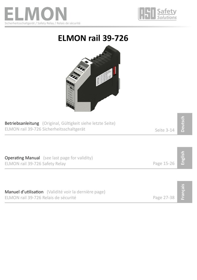
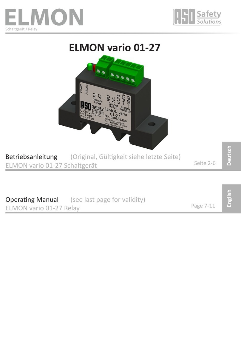
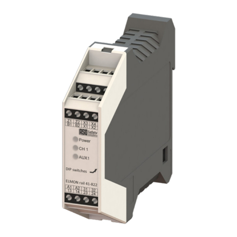
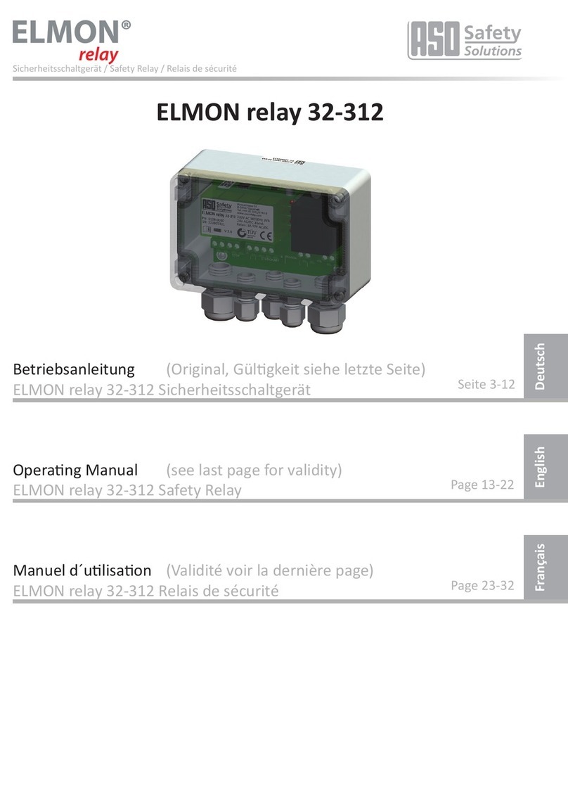
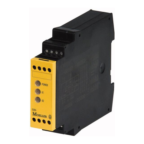
ELMON 32-242 User manual

Sicherheitsschaltgerät / Safety Relay / Relais de sécurité
ELMON relay 32-242
Betriebsanleitung (Original,GülgkeitsieheletzteSeite)
ELMON relay 32-242 Sicherheitsschaltgerät
OperangManual (seelastpageforvalidity)
ELMON relay 32-242 Safety Relay
Manueld´ulisaon (Validitévoirladernièrepage)
ELMON relay 32-242 Relais de sécurité
Page 13-21
DeutschEnglishFrançais
Seite 3-12
Page 22-31

12 13
English
ELMON relay 32-242
Safety Relay
1. Table of contents
1. Table of contents . . . . . . . . . . . . . . . . . . . . . . . . . . .13
2. Generalsafetyregulaonsandprotecvemeasures . . . . . . .14
3. Generalandoperaonaldescripon. . . . . . . . . . . . . . . . .15
4. Intended use . . . . . . . . . . . . . . . . . . . . . . . . . . . . . .15
5. Exampleinuse . . . . . . . . . . . . . . . . . . . . . . . . . . . . .16
6. Deviceoverview . . . . . . . . . . . . . . . . . . . . . . . . . . . .16
6.1 Signal displays . . . . . . . . . . . . . . . . . . . . . . . . . . . . . . . . . . 16
6.2 Conneconterminals . . . . . . . . . . . . . . . . . . . . . . . . . . . . . . 17
7. Mechanicalmounng . . . . . . . . . . . . . . . . . . . . . . . . .17
8. Electricalconnecon . . . . . . . . . . . . . . . . . . . . . . . . .18
8.1 Supply voltage . . . . . . . . . . . . . . . . . . . . . . . . . . . . . . . . . . 18
8.2 Sensorconnecon . . . . . . . . . . . . . . . . . . . . . . . . . . . . . . . . 18
8.3 Connecngseveralsensorspersensorcircuit . . . . . . . . . . . . . . . . . 18
8.4 Connecngcontrolcircuits . . . . . . . . . . . . . . . . . . . . . . . . . . . 19
9. Commissioningandperformancetesng . . . . . . . . . . . . . .19
10. Error diagnosis . . . . . . . . . . . . . . . . . . . . . . . . . . . . .19
11. Decommissioning and disposal. . . . . . . . . . . . . . . . . . . .19
12. Technical Data . . . . . . . . . . . . . . . . . . . . . . . . . . . . .20
13. ECdeclaraonofconformity . . . . . . . . . . . . . . . . . . . . .21
We reserve the right to make technical and operaonally relevant changes to the
products and devices described in this documentaon at any me and without prior
noce.

14
Safety Relay
English
2. General safety regulaons and protecve measures
• Manufacturersandusersoftheplant/machinery,forwhichtheprotecvedeviceisused,arethem-
selvesresponsibleforcoordinangandobservingalltherelevantsafetyinstruconsandregulaons.
• Theprotecvedeviceensuresoperaonalsafetyincombinaonwiththeoverridingcontrols,butnot
thesafetyoftheenreplant/machinery. Before usingthedeviceasafetyassessmentofthe enre
plant/machineryintermsoftheMachineryDirecve2006/42/ECoroftherelevantproductstandard
isrequired.
• Theoperanginstruconsmustalwaysbeavailableatthelocaonwheretheprotecvedeviceisused.
Theymustbereadandappliedthoroughlybyeveryonetaskedwiththeoperaon,servicingandmain-
tenanceoftheprotecvedevice.
• Installaonandcommissioningoftheprotecvedevicemayonlybecarriedoutbyqualiedsta,who
areacquaintedwiththeseoperanginstruconsandtherelevantinstruconsonoccupaonalsafety
andaccidentprevenon.Thedireconscontainedin theseoperanginstruconsmustbeobserved
andadheredtowithoutfail.
• The electrical engineering and professional society safety rules are to be observed.
• Whenworkingontherelay,itmustbedisconnectedfromthepowersupply,testedforzeropotenal
andsecuredagainstreconnecon.
• Ifthezeropotenalcontactsofthesafetyrelaycontactsaresuppliedbyanexternalhazardousvoltage,
thismustalsobeswitchedoduringworktotherelay.
• Therelaycontainsnocomponentsforservicingbytheuser.Unauthorisedmodicaonsand/orrepairs
totherelaywillresultinthecancellaonofallguaranteeorliabilityonthepartofthemanufacturer.
• Theprotecvesystemmustbetestedatappropriateintervalsbyexpertsandmustbedocumentedina
comprehensiblewayatallmes.
Safety instrucons
• Therelayallowsoperaonfrom24VAC/DC.Connecngtheoperangvoltagetothewrongterminals
may damage the relay.
• Therelaymustbeinstalledinacontrolbox.
• Do not install in the immediate vicinity of an intense heat source.
• Anadequateprotecvecircuitmustbeprovidedwithcapaciveandinducveusers.
Forthestandardiseddesignofthesafetysystem,theequipmentmustbetestedforcorrect
operaonbyexpertsatappropriateintervals.Thetesngmustbecomprehensiblydocumented
atallmes.
In the event of non-compliance or deliberate misuse, the manufacturer’s liability lapses.

14 15
ELMON relay 32-242
Safety Relay
English
3. General and operaonal descripon
Therelayisforevaluangsensors,includingsafetycontactmats,safetycontactstripsandsafetybumpers
formakingsafepinchandshearpoints.
Two separate signalling circuits can be connected to the relay, each controlling a switching output. The
quiescentcurrentmonitorofthesensorisenabledbyanintegratedterminatorinthesensor.
Therelaymonitorsthesetwosignallingcircuitspermanentlyforacvaonorbreaking(cablebreak).Ifthe
expectedquiescentcurrentisowing,theoutputrelaysareoperatedandtheswitchcontactsareclosed.If
thesensorisacvatedorthesensorcircuitisbroken,therelayswitchcontactsopen.
TherelayisdesignedinaccordancewithENISO13849-1:2015forCategory3.TocomplywithCategory3
therelayismanufacturedredundantandwithtwomutuallyacvangforciblyguidedsafetyrelays.
ThemonitoringstateofthesensorandtheoperangvoltagesuppliedareshownbyLEDs.
Intheeventofafaultalarm,allsafetyoutputsareinacve.
Theunitcan beusedina household environment as wellasan industrialenvironmentup to
analtudeof2000mabovemeansealevel.Theunitmustnotbeoperatedinareaswithmajor
temperature changes.
4. Intended use
Therelayisabletofullitssafetytaskonlyifitisusedforthepurposeitwasdesignedfor.
Appropriateulisaonoftherelayisuseasaprotecvedeviceincombinaonwithsafetycontactmats,
safetybumpersandsafetycontactstripsof8.2kΩresistancetoquiescentcurrentmonitoring.
Anyulisaonbeyondthis does notconstuteappropriateintendeduse. The manufactureraccepts no
liability for damage arising from inappropriate use.
Useinspecialapplicaonsrequirestheapprovalofthemanufacturer.
Theuseofthesafetyrelayatheightsabove2000mabovesealevelorinpotenallyexplosiveareasisnot
approved.
ELMON relay 32-242 Block circuit diagram
Stop
Channel 1
Stop
Channel 2
Sensor
Channel 2
Sensor
Channel 1
Rref +Ub
Uref
Rref +Ub
Uref
Rel
Rel
24V AC/DC

16
6. Device overview
6.1 Signal displays
LED Power(green)
Operaonmode(on)
Faultalarm(pulse)
LED Channel 1(red)
Sensoracvated(on)
Sensorcircuitbroken(ashesrapidly)
Faultself-lock(ashesslowly)
LED Channel 2(red)
Sensoracvated(on)
Sensorcircuitbroken(ashesrapidly)
Faultself-lock(ashesslowly)
5. Verwendungsbeispiele
Circuit diagram in zero poten al state. Sensor not ac vated.
ELMON relay 32-242
+24 V DC
0 V DC
Sensor CH1
Sensor CH2
SPS
Machine
Control
8,2kΩ
8,2kΩ
10311
9
8 4 5 6 7
Out CH 1
Out CH 2
K3 K3
K1 K2
A1 A1
A2 A2
24
K3 A1
A2
Q1.1
A2
I1.2I1.1A1
K1 K2
1 3 5 1 3 5
2 4 62 4 6
L1 L2 L3 L1 L2 L3
Safety Relay
English

16
17
7. Mechanical moun ng
Theswitchingunitmustbemountedcorrectly:
• Inadust-protectedandmoistureprotectedswitchcabinetorcasing.
• Foruseinanenvironmentwithcontaminaonlevel2.
• WithaprotecontypeofatleastIP54.
• On a 35 mm DIN support rail according to EN 50 022.
Theswitchingunitmustnotbeinstalledintheimmediatevicinityofanintenseheatsource.
Theswitchingunitcanbeinstalledinanyposion.
Theunitmustnotbeoperatedinareaswithmajortemperaturechanges.
ELMON relay 32-242
Safety Relay
English
Ifthereisnofaultalarm,theoperangstateisshownviatheLEDPower(on).Whensignallingafaultalarm
thenumberofpulsesemiedindicatesthenatureofthefault:
Pulse Fault alarm
1 Supply voltage outside the available range
3 Output control Stop Channel 1 faulty
4 Output control Stop Channel 2 faulty
5Datatransferbetweenmicrocontrollersfaulty
6Errorintesngsignalinput(Channel 1 / Channel 2)
6.2 Connec on terminals
Pin 1 2 (Notallocated)
Pin 3 11 Signal input Channel 1
Pin 3 10 Signal input Channel 2
Pin 4 5 Relay output to Channel 1 control
Pin 6 7 Relay output to Channel 2 control
Pin 8 9 Supply voltage 24 V AC/DC
8
765
4
9
10
3
2
111

18
8. Electrical connecon
Connecontothewrongterminalsmaydamagetherelay.
Wiringlaidintheopenoroutsidethecontrolboxmustbeproperlyprotected.
Thesignalwiringmaynotbeconnectedparalleltothemotorwiringorotherpowerwiring.
Thelimitsshowninthe“TechnicalData”forthesupplyvoltageandrelayswitchingcapacitymust
beobserved.Sucientfuseproteconmustbeprovidedonalloutputcontactswithcapacive
andinducveloads.
8.1 Supply voltage
The supply voltage is to be connected to the terminal pair 8 924VAC/DC.Thesupplywiringtotherelaymust
beprotectedbyasuitablecircuitbreaker.Thesupplyvoltagemustmeettherequirementsforlowvoltage
protecon(SELV).
8.2 Sensor connecon
Connect the sensor for Channel 1 to the terminal pair 3 11. Connect the sensor for Channel 2 to the terminal
pair 3 10.
Ifachannelisnotused,itmustbeedwithan8.2kΩresistance.
8.3 Connecng mulple sensors per sensor circuit
ASO sensors must not be connected in parallel.
One or more sensors can be connected to sensor input. For this purpose, the individual sensors are connec-
tedinseriesaccordingtogure1.
Safety edges SENTIR edge:
UptoveSENTIRedgemaybeconnectedinseries.ThemaximumtotallengthotheSENTIRedgeshall
notexceed100m.
The length of one SENTIR edge may be up to 25 m.
ThetotalcablelengthotheinseriesconnectedSENTIRedgemustnotexceed25m.
Safety bumper SENTIR bumper:
UptoveSENTIRbumpermaybeconnectedinseries.ThemaximumtotallengthotheSENTIRbumper
shallnotexceed15m.
The length of one SENTIR bumper may be up to 3 m.
ThetotalcablelengthotheinseriesconnectedSENTIRbumpermustnotexceed25m.
Safety contact mat SENTIR mat:
UptotenSENTIRmatmaybeconnectedinseries.Themaximumtotalareashallnotexceed10m2.
ThemaximumsizeofanSENTIRmatis1350x2350mm.Thetotalcablelengthotheinseriesconnected
SENTIRmatmustnotexceed25m.
Beforeconnecngthesensorsthatareconnectedinseries,itisrecommendedthattheresistancevalueof
thearrangementistobemeasured.Theresistancemustbe8.2kΩ±500Ωwhenthesensorisinacveand
mustnotexceed500Ωwhenitisacve.
Safety Relay
English
Sensor „n“
Sensor 2
Sensor 1
Opening
Figure 1: Connecon of mulple sensors; in this example: safety contact edge
2
222

18 19
ELMON relay 32-242
Safety Relay
English
Figure 1: Connecon of mulple sensors; in this example: safety contact edge
8.4 Connecng control circuits
The control circuit to be monitored for Channel 1 is to be connected to the terminal pair 4, 5and the corre-
sponding control circuit for Channel 2 is to be connected to the terminal pair 6, 7.
Thecontrolcircuitsmustbeprotectedbyacorrespondingcircuitbreakerdependingontheratedcurrentor
theratedcurrentinthecontrolcircuitsmustbelimitedtothemaximumvaluebyothermeans.
Therelaycontactmayonlyswitchextralowvoltages(30V).Theswitchingoflowvoltages(230V)
is not permissible.
9. Commissioning and performance tesng
Aeralltheelectricalcontactshavebeenconnectedandthesupplyvoltageswitchedon,theplant/machinery
mustbetestedforproperfunconing.
Followingsuccessfulcommissioningthesafetyoutputs4, 5and 6, 7areacvated(relaycontacts“closed”).
Acvangtheannunciatorresultsinopeningtherelaycontacts.
Thesafetysystemmustbetestedbyqualiedstaatappropriateintervals.Thetesngmustbecomprehen-
siblydocumentedatallmes.Therequirementsoftheplant/machinerymanufacturermustbeobserved
and adhered to.
10. Error diagnosis
Ifthewiringandconnecngupofthesupplyvoltageiscorrect,onlythegreenLEDPowershouldlightup.Ifthe
redLEDlightsupthereisafaultinthesystem,whichcanbeisolatedwiththeaidoftheLED.
* Ifthefaultisnotinthewiring,thefunconingoftheelectronicsmaybecheckedbyngan8.2kΩ
resistancetotheannunciatorinputontherelay.Iftheelectronicsthenworkproperly,theannunciator
mustbetestedwithanohmmeter.Forthistheconneconbetweentheannunciatorandtherelaymust
bedisconnectedandconnectedtoanohmmeter.Withaninacvatedannunciatortheresistanceshould
be8.2kΩ±500Ω.Iftheannunciatorisacvated,theresistanceshouldnotexceed500Ω.
11. Decommissioning and disposal
ProductsmanufacturedbyASOareintendedexclusivelyforcommercialuse(B2B).Attheendoftheirservice
theproductsshouldbedisposedofinaccordancewiththelocal,regionalandnaonalregulaons.ASOwill
bepleasedtocollecttheproductsfordisposalinaccordancewiththeregulaons.
LED Error Error correcon
green LED
Power
does not light up
Supply voltage absent,
toolow
orwronglyconnected.
Testconneconsandsupplyvoltage:
- 24 V AC/DC to terminals 8 9, tolerancerange:±10%
green LED
Power
ashescyclically(pulse)
Internalfaultisshownbythe
number of pulses. See -> Signal displays
red LED
Channel 1 / Channel 2
lights up
The relevant sensor
isrecognisedasacvated.
-Checkconneconsoftherelevantsensors
(pinchedwiring,brilewiringetc.)
-Checksensor*
red LED
Channel 1 / Channel 2
ashesrapidly
Sensorcircuitbroken,
sensor not connected,
connected incorrectly or faulty
-Checkconneconsoftherelevantsensors
(pinchedwiring,brilewiringetc.)
-Checksensor*

20
Safety Relay
English
12. Technical Data
Supply voltage
Lowvoltage: UE 24VAC/DC±10%
IE85 mA
Imax 180mA(100ms)
Inputpower: PE-max 3 W 24 V DC
PE-max 3 VA 24 V AC
Ensuringlow
voltage(external): 125mAMediumacngfuse
125mAFlinkcanbeused
alternavely
Terminal resistance o the sensor
nominal value Rnom 8,2kΩ
upperswitchingpoint RAO >12,0kΩ
lowerswitchingpoint RAU <5,0kΩ
Safety relay
Nominal current DC DC-13 / 24 V / 2 A
Nominal current AC AC-15 / 30 V / 2 A
Mechanicallife-me >106actuaons
Sa ey Relay
Fusetype M2A5x20glasstube*
Safety relay switching mes
Switchingodelay <12ms
(responseme)
Turn-ome 500ms(ELMONrelay32-242)
100ms(ELMONrelay32-242K)
(Poweron700ms)
Assembly Plug-insocketto35mmDINsnap-onrail
Housing 11pol.DINplug-insockethousing
withplug-insocketfor35mmassemblyrail
Dimensions (HxWxD)
Housing
82x38x84mm
Housingincl.plug-insocket 82x38x110mm
Protec on class IP20
Weight 225 g
Temperature range -25°C to +55°C
Connec on terminals
ghteningtorque 0,5Nm
Connec on cable cross-sec on single-orne-strandedcable0,75-1,5mm2
Cer ca ons
EN ISO 13849-1:2015
Categorie 3 PL e
MTTFd180years,DC90%
Electronics MTTFd3757years,DC90%
Electromechanics B10d1000000/MTTFd190years(Nop52560)
All voltages connected to the switching unit must be safely isolated!
*Not included in the scope of delivery
84
82
38
26

20 21
ELMON relay 32-242
Safety Relay
English
13. EC declaraon of conformity
ELMON relay 32-302*
ELMON relay 32-312* **
ELMON relay 32-242**
ELMON relay 32-332*
ELMON relay 32-302*
ELMON relay 32-312* **
ELMON relay 32-242**
ELMON relay 32-332*
ELMON relay 32-302*
ELMON relay 32-312* **
ELMON relay 32-242**
ELMON relay 32-332*
Table of contents
Other ELMON Relay manuals
