ELNA eXpressive 970 User manual

eXpressive 970
| Instruction Manual |


I
IMPORTANT SAFETY INSTRUCTIONS
When using an electrical appliance, basic safety precautions should always be followed, including the
following:
This sewing machine is designed and manufactured for household use only.
Read all instructions before using this sewing machine.
DANGER— To reduce the risk of electric shock:
1. An appliance should never be left unattended when plugged in. Always unplug
this sewing machine from the electric outlet immediately after using and before
cleaning.
WARNING—To reduce the risk of burns, fire, electric shock, or injury to persons:
1. Do not allow to be used as a toy. Close attention is necessary when this sewing machine is used
by or near children.
2. Use this appliance only for its intended use as described in this owner’s manual.
Use only attachments recommended by the manufacturer as contained in this owner’s manual.
3. Never operate this sewing machine if it has a damaged cord or plug, if it is not working properly, if
it has been dropped or damaged, or dropped into water.
Return this sewing machine to the nearest authorized dealer or service center for examination,
repair, electrical or mechanical adjustment.
4. Never operate the appliance with any air opening blocked. Keep ventilation openings of this
sewing machine and foot controller free from accumulation of lint, dust and loose cloth.
5. Never drop or insert any object into any opening.
6. Do not use outdoors.
7. Do not operate where aerosol (spray) products are being used or where oxygen is being
administered.
8. To disconnect, turn all controls to the off (“O”) position, then remove plug from outlet.
9. Do not unplug by pulling on cord. To unplug, grasp the plug, not the cord.
10. Keep fingers away from all moving parts. Special care is required around the sewing machine
needle and/or cutting blade.
11. Always use the proper needle plate. The wrong plate can cause the needle to break.
12. Do not use bent needles.
13. Do not pull or push fabric while stitching. It may deflect the needle causing it to break.
14. Switch this sewing machine off (“O”) when making any adjustment in the needle area, such as
threading the needle, changing the needle, threading the bobbin or changing the presser foot, and
the like.
15. Always unplug this sewing machine from the electrical outlet when removing covers, lubricating, or
when making any other adjustments mentioned in this owner’s manual.
SAVE THESE INSTRUCTIONS
Please note that on disposal, this product must be safely recycled in accordance with relevant
National legislation relating to electrical/electronic products. If in doubt please contact your
retailer for guidance. (European Union only)
For Europe only:
This appliance can be used by children aged from 8 years and above and persons with reduced
physical, sensory or mental capabilities or lack of experience and knowledge if they have been given
supervision or instruction concerning use of the appliance in a safe way and understand the hazards
involved. Children shall not play with the appliance. Cleaning and user maintenance shall not be made
by children without supervision.
For outside Europe (except U.S.A and Canada):
This appliance is not intended for use by persons (including children) with reduced physical, sensory or
mental capabilities, or lack of experience and knowledge, unless they have been given supervision or
instruction concerning use of the appliance by a person responsible for their safety.
Children should be supervised to ensure that they do not play with the appliance.

II
GROUNDING INSTRUCTIONS
This product must be grounded. In the event of malfunction or breakdown, grounding provides a path of least
resistance for electric current to reduce the risk of electric shock.
This product is equipped with a cord having an equipment grounding conductor and a grounding plug.
The plug must be plugged into an appropriate outlet that is properly installed and grounded in accordance with
all local codes and ordinances.
DANGER Improper connection of the equipment-grounding conductor can result in a risk of
electric shock.
1. The conductor with insulation having an outer surface that is green with or without yellow stripes is the
equipment-grounding conductor.
2. If repair or replacement of the cord or plug is necessary, do not connect the equipment-grounding
conductor to a live terminal.
3. Check with a qualified electrician or serviceman if the grounding instructions are not completely
understood, or if in doubt as to whether the product is properly grounded.
Do not modify the plug provided with the product if it will not fit the outlet, have a proper outlet installed by
a qualified electrician.
4. This product is for use on a nominal 120 V circuit, and has a grounding plug that looks like the plug illustrated
in Fig. A. A temporary adaptor, which looks like the adaptor illustrated in Fig. C, may be used to connect this
plug to a 2-pole receptacle as shown in Fig B. If a properly grounded outlet is not available, the temporary
adapter should be used only until a properly grounded outlet can be installed by a qualified electrician.
The green colored rigid ear, lug, and the like, extending from the adaptor must be connected to a permanent
ground such as a properly grounded outlet box cover. Whenever the adaptor is used, it must be held in place
by the metal screw.
Fig. A
Fig.B Fig.C
Metal screw
grounding means
Fig.C
II

1
TABLE OF CONTENTS
SETTING UP THE MACHINE
Installing the Machine...................................................... 2
Adjusting the feet...........................................................3
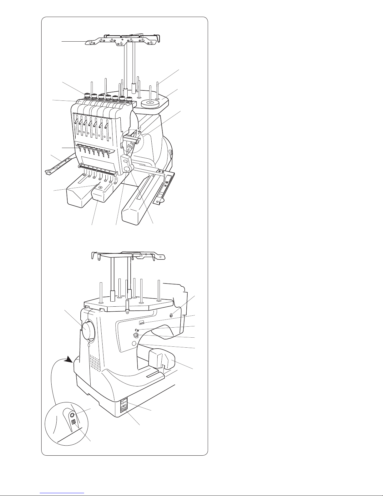
Names of Parts................................................................5
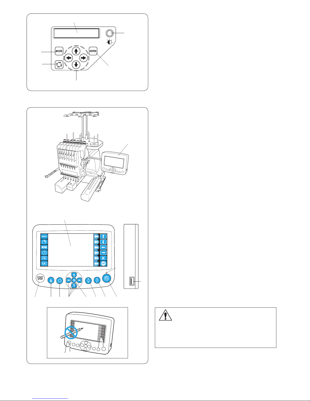
Sub control panel ..........................................................6
RCS unit (optional for some models) ............................6
Standard Accessories.................................................7-8
Assembling the Spool Stand ...........................................9
Setting the Thread Cones or Spools of Thread .............10
Setting the spool of thread ..........................................10
Setting the thread cone ...............................................10
Installing the Hoop Supporter........................................ 11
Installing the RCS Unit (optional for some models)....... 12
Connecting the Power Supply .......................................13
Direct PC-Link ............................................................... 14
Winding the Bobbin .......................................................15
Removing the bobbin case..........................................16
Removing the bobbin ..................................................16
Inserting the bobbin.....................................................17
Inserting the bobbin case ............................................17
Threading the Needle...............................................18-20
Threading the needle with the needle threader...........20
Stabilizers...................................................................... 21
Template........................................................................21
Setting the Fabric in the Embroidery Hoop....................22
Setting the Embroidery Hoop ........................................23
Adjusting the Hoop Supporter for Optional Hoops ........23
BASIC OPERATION
Basic Operation with the Sub Control Panel .................24
Machine operating buttons .......................................... 24
Function buttons..........................................................24
LCD screen .................................................................25
Machine setting ........................................................26-27
Starting to Embroider................................................28-29
Removing the Hoop....................................................... 30
Adjusting the Thread Tension ........................................31
Replacing the needle..................................................... 32
Basic Operation of the Optional RCS Unit.....................33
Machine operating buttons .......................................... 33
Panel keys...................................................................34
On-screen Help Movie...................................................35
Disconnecting the RCS Unit.......................................... 36
ADVANCED OPERATION WITH THE OPTIONAL
RCS UNIT
Selecting the Embroidery Patterns................................ 37
Selecting the built-in designs..................................38-39
Function keys ...........................................................40-41
Monogramming..............................................................42
Function keys .............................................................. 43
Entering the characters ...............................................44
Deleting a character ....................................................45
Inserting a character.................................................... 45
Saving the monogram .................................................45
Placement of monogramming .....................................46
Multi-color monogramming..........................................47
Editing............................................................................48
Editing Functions........................................................... 49
Selecting the hoop.......................................................49
Moving the pattern.......................................................50
Resizing the pattern ....................................................50
Rotating the pattern.....................................................51
Deleting the pattern ..................................................... 51
Saving the le..............................................................51
Alternate function key assignment ..............................52
Duplicating the pattern ................................................52
Flipping the pattern......................................................52
Monogramming in an arc............................................. 53
Customizing the color setting ......................................54
Grouping the patterns.................................................... 55
Color grouping.............................................................55
Zooming the editing window.......................................... 56
Combining the Patterns and Lettering......................57-59
Adjusting the start position ............................................60
Adjusting the re-start position after thread breakage.....60
Starting to Embroider.....................................................61
Customizing the Settings with the
Sub Control Panel ....................................................62-66
Customizing the Settings with the Optional
RCS Unit...................................................................67-77
File Management...........................................................78
Saving the Pattern as a File ........................................78
Creating a new folder ..................................................79
Changing the folder name ........................................... 79
Opening a le ..............................................................80
File list option ..............................................................81
Deleting the folder .......................................................82
Deleting the le............................................................82
OPTIONAL ITEMS
USB Flash Drive............................................................ 83
CARE AND MAINTENANCE
Cleaning the Hook......................................................... 84
Cleaning the Bobbin Case............................................. 84
Cleaning the Tension Leaves and Disks........................85
Cleaning the Auto Thread Cutter Mechanism................86
Oiling ........................................................................87-88
Error Message............................................................... 89
Troubleshooting........................................................90-91

2
q
q
w
e
SETTING UP THE MACHINE
Installing the Machine
Place the machine on a at and stable surface such as
a sturdy table that could withstand the machine’s weight
and vibration.
Place the machine on the at and level surface.
Make sure that all the feet rmly contact the surface.
Provide a sufcient space around the machine to
allow the hoop to move freely.
q 20 cm (7–7/8˝)
w 20 cm (7–7/8˝)
e 30 cm (11–7/8˝)

3
A
q
w
B
e
e
e
Adjusting the feet
Turn the adjusting screw counterclockwise (in the
direction of A) as much as possible, before placing the
machine on a surface.
qAdjusting screw
Place the machine on a at and level surface.
Turn the adjustable foot so the four feet rmly contact the
surface.
wAdjustable foot
eFoot
Turn the adjusting screw clockwise (in the direction B)
until it contacts the surface.
NOTE:
Make sure that the machine sits on the surface without
shaking.

4
q
CAUTION:
Do not use the machine near appliances that radiate
electromagnetic noise such as a microwave oven, or
do not plug in the machine to the same branch circuit
where such appliances are connected.
CAUTION:
Do not use or store the machine near a heat radiator
or in a place with dust or high humidity.
CAUTION:
Do not expose the machine to direct sunlight or open
air.
CAUTION:
Two or more persons are required when transporting
the machine.
Hold the machine by the two legs and the hand grip
on the bottom of the backside of the machine.
qHand grip
* Remove the hoop supporter when transporting the
machine to avoid damage by hitting the supporter.

5
q
w
e
r
t
y
i
uo
!0
!3
!4
!6
!7
!8
!9
@1
@2
@0
!2
@3
!1
!5
Names of Parts
qThread guide bar
wPre-tension control
eTension control
rCheck spring
tHoop supporter
yNeedle plate
uHook cover
iSTART/STOP button
oAuto thread cutter button
!0 Sub control panel
!1 Spool stand
!2 Spool pins
* For assembling the thread guide bar and the
spool stand, refer to page 9.
*
For installing the hoop supporter, refer to page 11.
!3 Machine socket
!4 Power switch
!5 Carriage
!6 Bobbin winder button
!7 Bobbin winder stopper
!8 Bobbin winder spindle
!9 Bobbin thread cutter
@0 Bobbin winder thread guide
@1 Handwheel
@2 RCS connector socket
@3 USB port

6
CAUTION:
Do not press the LCD touch panel with hard or sharp
pointed objects like pencils, screwdrivers or the like.
Press the LCD touch panel and buttons gently.
Rough or forceful pressing may damage the unit.
wertyu
q
w
e
r
t
o
i
!2
y
!1
!0
q
Sub control panel
qMODE button
wTrace button
eArrow buttons
rENTER button
tLCD brightness adjusting dial
yLCD display
RCS unit (optional for some models)
qRCS unit
wSTART/STOP button
eAuto thread cutter button
rTrace button
tJog buttons
yCarriage return button
uStitch back button
iStitch forward button
oBobbin winder button
!0 Bobbin winder indicator
!1 USB port
!2 LCD touch panel
* The RCS unit is for 7-needle embroidery machine only
and cannot be used for other models.

7
q w
e r
t y
u
i
o !0
!1
!3
!2
!4
Standard Accessories
qNeedle (DB x K5Q1-NY, #11) (x 10)
wScissors
eBobbin (x 5)
rLint brush
tSeam ripper
yHandy needle threader
uSpool cap (x 8)
iSpool net (x 15)
oScrewdriver
!0 Screwdriver (small)
!1 Oiler
!2 Tweezers
!3 Offset screwdriver
!4 Accessory box

8
y
u
i
eq
o
r
!0
!1
!2
!4
!5
!6
!7 !8
!9
t
w
@0
Standard Accessories
qInstruction book
wInstructional DVD
ePower supply cable
rUSB cable
tScrewdriver (large)
yHoop M1
(MB Hoop 240 x 200 mm)
(with template)
uHoop M2
(MB Hoop 126 x 110 mm)
(with template)
iHoop M3 (MB Hoop 50 x 50
mm
)
(with template)
oHoop supporter
!0 Felt ring (large) (x 8)
!1 Felt ring (small) (x 8)
!2 Spool rest (x 8)
!3 Thread guide bar
!4 Spool stand
!5 Thread guide pole (x 2)
!6 Setscrew (x 3)
!7 Setscrew A (x 2)
!8 Setscrew B (x 2)
!9 Spool pin A (x 7)
@0 Spool pin B (x 1)
!3
RCS unit (optional for some models)

9
v Attach the assembled spool stand to the machine with
the 3 setscrews.
iSetscrews
i
i
Assembling the Spool Stand
zInsert the spool pins A into the spool stand.
Insert the thread guide poles and secure the poles
with setscrews A from the bottom.
qThread guide poles
wSetscrews A
eSpool stand
rSpool pin A
xInsert the spool pin B into the spool stand.
tSpool pin B
q
w
e
y
u
q
r
t
v
c
z x
cAttach the thread guide bar to the thread guide poles
with the setscrews B.
* Tighten the setscrews rmly with the screwdriver
(large).
yThread guide bar
uSetscrews B

10
r
w
w
e
u
i
!0
w
w
t
o
y
e
q
q
e
Setting the Thread Cones or Spools of Thread
Felt rings of two sizes are provided to accommodate
various types of spools of thread and thread cones.
Use the large felt rings for large thread cones.
For small thread cones or spools of thread, insert the
small felt rings into the large rings.
qSpool of thread
wSpool pin
e Felt ring (large)
rFelt ring (small)
tSmall spool of thread
ySpool pin for bobbin winding
Setting the spool of thread
Place the spool of thread on the spool pin, with the thread
coming out from the left backside.
Attach the spool cap and rmly press it against the spool.
wSpool pin
uSpool cap
Setting the thread cone
Attach the spool rests on the spool pins.
Place the thread cones on the spool pins.
Cover the thread cone with the spool net if the thread is
shaky or kinky when sewing.
If the net is too long for a spool, fold the net and place it
on the spool.
qSpool of thread
wSpool pin
iSpool rest
oSpool net
NOTE:
To prevent the thread from unraveling, leave the net on
the thread cone or hook the thread end into the notch
of the spool when it is not in use.
!0 Notch

11
x Hold the hoop supporter with both hands and place it
under the carriage plate by inserting the necks of both
thumbscrews into the slots in the carriage plate.
eSlot in the carriage plate
q
w
e
w
w
c Tighten the thumbscrews with the screwdriver to
secure the hoop supporter.
* When carrying the machine, remove the hoop supporter
from the machine.
Installing the Hoop Supporter
CAUTION:
Turn the power switch off before installing the hoop
supporter.
z Loosen the two thumbscrews on the hoop supporter.
qHoop supporter
wThumbscrew
c
x
z

12
Installing the RCS Unit (optional for some models)
z Loosen the thumbscrew and open the mounting arm.
qThumbscrew
wMounting arm
x Loosen the screw knob A and set the RCS unit on the
mounting arm by hooking the RCS unit on the pins.
Tighten the screw knob A to secure the RCS unit.
eScrew knob A
rRCS unit
tPin
c Adjust the angle of the mounting arm as desired and
tighten the thumbscrew.
qThumbscrew
wMounting arm
v Insert the connector into the connector socket on the
back of the machine with the marks aligned.
yConnector socket
u Connector
iMark
n Loosen the screw knob B on the end of the mounting
arm and tilt the RCS unit to adjust the angle of the
LCD screen for easier viewing.
m Tighten the screw knob B to secure the RCS unit.
rRCS unit
!3 Screw knob B
If you want to use the RCS unit without installing, extend
the two legs on the backside of the RCS unit so that it
rests on an angle for easier viewing.
!4 Leg
w
e
r
t
q
z x c
n m
v
b
y
u
!3
r
!4
o
i
!0
!1
!2
b Fold and secure the cable under the spool stand as
shown.
oSpool stand
!0 Cable slotted into ribs
!1 Cable coming from connector
!2 Excess cable secured in the opening
CAUTION:
Make sure to secure the cable under the spool stand.
A loose cable may interfere with the hoop.
View from the bottom

13
q
w
e
r
t
Connecting the Power Supply
CAUTION:
Turn the power switch off before connecting the
machine to the power supply.
z Turn the power switch off.
qPower switch
x Insert the machine plug into the machine socket.
wMachine plug
eMachine socket
c Insert the power supply plug into the properly
grounded outlet.
rPower supply plug
tWall outlet (grounded)
v Turn the power switch on.
qPower switch
CAUTION:
While in operation, always keep your eyes on
thevsewing area, and do not touch any moving parts
such as the thread take-up lever, handwheel or
needle.
Always turn off the power switch and unplug the
machine from the power supply:
- when leaving the machine unattended.
- when attaching or removing parts.
- when cleaning the machine.
Grounding Instructions:
This machine is equipped with a grounding cable and
plug.
The plug must be plugged into an appropriate outlet that
is properly installed and grounded.
If a properly grounded outlet is not available, contact
a qualied electrician to install the properly grounded
outlet.
Refer to page II for more instructions.
z
v
c
x

14
PC M
Direct PC-Link
The machine can be connected to PC with the USB cable
included as standard accessory.
You need Digitizer V5 software (optional item) to operate
the machine via direct PC-link.
qType A USB connector
wType B USB connector
eTransferring the data
Connecting the Machine and PC
Start up the machine and PC, and insert the type A USB
connector into the PC.
Insert the type B USB connector into the USB port on the
machine.
For operating instructions, refer to the instruction manual
of Digitizer V5.
Embroidery Data Format
The following embroidery data formats can be used
with this machine.
(1) .jef (Janome embroidery format)
(2) .jef + (editable Janome embroidery format)
(3) .dst (Tajima embroidery format)
* Tajima format (.dst) does not have thread color
information. Madeira (Rayon 40) thread color
information will be assigned automatically.
q
w
CAUTION:
Do not turn the power switch off or disconnect the
USB cable while the data transfer is in progress.
Otherwise the data will be lost or the memory will be
damaged.
e

15
Winding the Bobbin
NOTE:
Cotton or spun polyester threads sizes 90 to 120 are
recommended for bobbin thread.
Do not use poor quality prewound bobbins.
zPlace the thread cone (spool of thread) on the rear
most spool pin.
xPass the thread through the thread guide A.
Pass the thread through the upper hole and lower hole
in the thread guide B.
qThread guide A
wThread guide B
z x
q
w
e
c
r
e
t
y
u
v b
nm
,
i
u
t
u
y
t
cDraw the thread to the front.
Hold the thread with both hands and pass the thread
rmly around and under the tension disk.
eTension disk
vPass the thread through the hole in the bobbin from
the inside.
Put the bobbin on the bobbin winder spindle.
rHole in the bobbin
tBobbin winder spindle
bPush the bobbin winder stopper up against the
bobbin.
yBobbin winder stopper
nPress the bobbin winding button while holding the
thread end.
uBobbin winder button
mPress the bobbin winder button to stop the machine
when the bobbin has wound a few layers.
Cut the thread close to the bobbin and press the
bobbin winder button again.
uBobbin winder button
,When the bobbin is fully wound, the machine will stop
automatically.
Remove the bobbin from the bobbin winder spindle.
tBobbin winder spindle
Cut the thread with the bobbin thread cutter.
iBobbin thread cutter
* Do not remove the thread from the bobbin thread
cutter after cutting the thread.

16
z
x
q
w
Removing the bobbin
Release the latch and take out the bobbin.
q Latch
w Bobbin
q
w
e
r
Removing the bobbin case
CAUTION:
Turn the power switch off before removing the bobbin
case.
zOpen the hook cover toward you.
qHook cover
xHold and open the latch of the bobbin case.
Take the bobbin case out from the machine.
wBobbin case
eLatch
CAUTION:
Do not force to pull the thread keeper when you
remove the bobbin case.
rThread keeper
Other manuals for eXpressive 970
1
Table of contents
Other ELNA Sewing Machine manuals

ELNA
ELNA PRO 704 DEX User manual

ELNA
ELNA Elnita ec60 User manual

ELNA
ELNA 6600 User manual

ELNA
ELNA 9500 - LEAFLET User manual

ELNA
ELNA 7300 - User manual

ELNA
ELNA eXperience 620 User manual

ELNA
ELNA 5000 computer User manual

ELNA
ELNA 744 User manual

ELNA
ELNA eXcellence 730 User manual

ELNA
ELNA 664PRO - User manual