ELNA eXtend 864air User manual

| Instruction Manual |
elna eXtend 864air


1
IMPORTANT SAFETY INSTRUCTIONS
When using an electrical appliance, basic safety precautions should always be followed, including the
following:
This Serger/Overlocker/Overlock machine is designed and manufactured for household use only.
Read all instructions before using this Serger/Overlocker/Overlock machine.
DANGER— To reduce the risk of electric shock:
1. An appliance should never be left unattended when plugged in. Always unplug
this
Serger/Overlocker/Overlock machine from the electric outlet immediately after
using and before cleaning.
WARNING— To reduce the risk of burns, re, electric shock, or injury to persons:
1. Do not allow to be used as a toy. Close attention is necessary when this Serger/Overlocker/Overlock
machine is used by or near children.
2. Use this appliance only for its intended use as described in this owner’s manual.
Use only attachments recommended by the manufacturer as contained in this owner’s manual.
3. Never operate this Serger/Overlocker/Overlock machine if it has a damaged cord or plug, if it is not
working properly, if it has been dropped or damaged, or dropped into water.
Return this Serger/Overlocker/Overlock machine to the nearest authorized dealer or service center
for examination, repair, electrical or mechanical adjustment.
4. Never operate the appliance with any air opening blocked. Keep ventilation openings of this
Serger/Overlocker/Overlock machine and foot controller free from accumulation of lint, dust and
loose cloth.
5. Never drop or insert any object into any opening.
6. Do not use outdoors.
7. Do not operate where aerosol (spray) products are being used or where oxygen is being
administered.
8. To disconnect, turn all controls to the off (“O”) position, then remove plug from outlet.
9. Do not unplug by pulling on cord. To unplug, grasp the plug, not the cord.
10. Keep ngers away from all moving parts. Special care is required around the Serger/Overlocker/
Overlock machine needle and/or cutting blade.
11. Always use the proper needle plate. The wrong plate can cause the needle to break.
12. Do not use bent needles.
13. Do not pull or push fabric while stitching. It may deect the needle causing it to break.
14. Switch this Serger/Overlocker/Overlock machine off (“O”) when making any adjustment in the
needle area, such as threading the needle, changing the needle or changing the presser foot, and
the like.
15. Always unplug this Serger/Overlocker/Overlock machine from the electrical outlet when removing
covers, lubricating, or when making any other adjustments mentioned in this owner’s manual.
SAVE THESE INSTRUCTIONS
Please note that on disposal, this product must be safely recycled in accordance with relevant
National legislation relating to electrical/electronic products. If in doubt please contact your
retailer for guidance. (European Union only)
For Europe only:
This appliance can be used by children aged from 8 years and above and persons with reduced
physical, sensory or mental capabilities or lack of experience and knowledge if they have been given
supervision or instruction concerning use of the appliance in a safe way and understand the hazards
involved. Children shall not play with the appliance. Cleaning and user maintenance shall not be made
by children without supervision.
For outside Europe (except U.S.A and Canada):
This appliance is not intended for use by persons (including children) with reduced physical, sensory or
mental capabilities, or lack of experience and knowledge, unless they have been given supervision or
instruction concerning use of the appliance by a person responsible for their safety.
Children should be supervised to ensure that they do not play with the appliance.

2
TABLE OF CONTENTS
ESSENTIAL PARTS
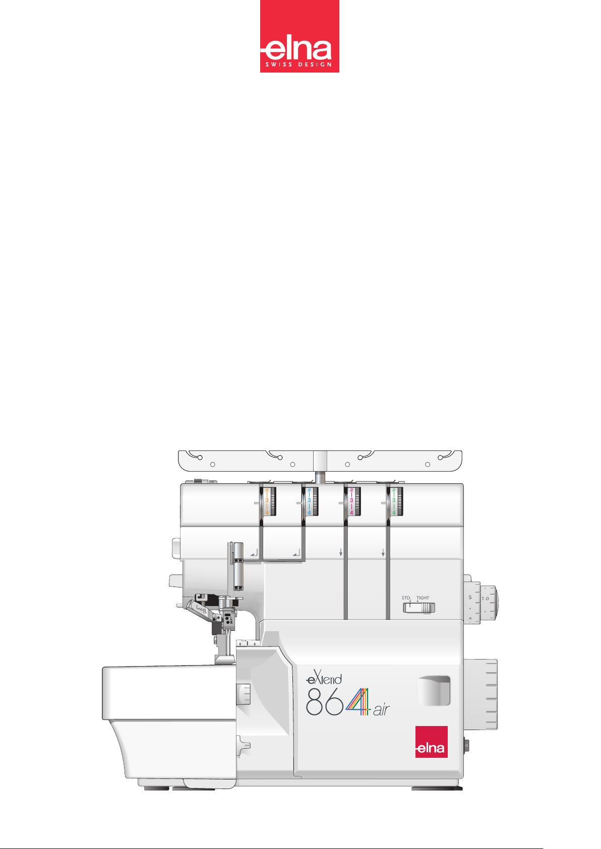
Names of Parts............................................................... 3
Safety Device ................................................................. 4
Standard Accessories .................................................... 5
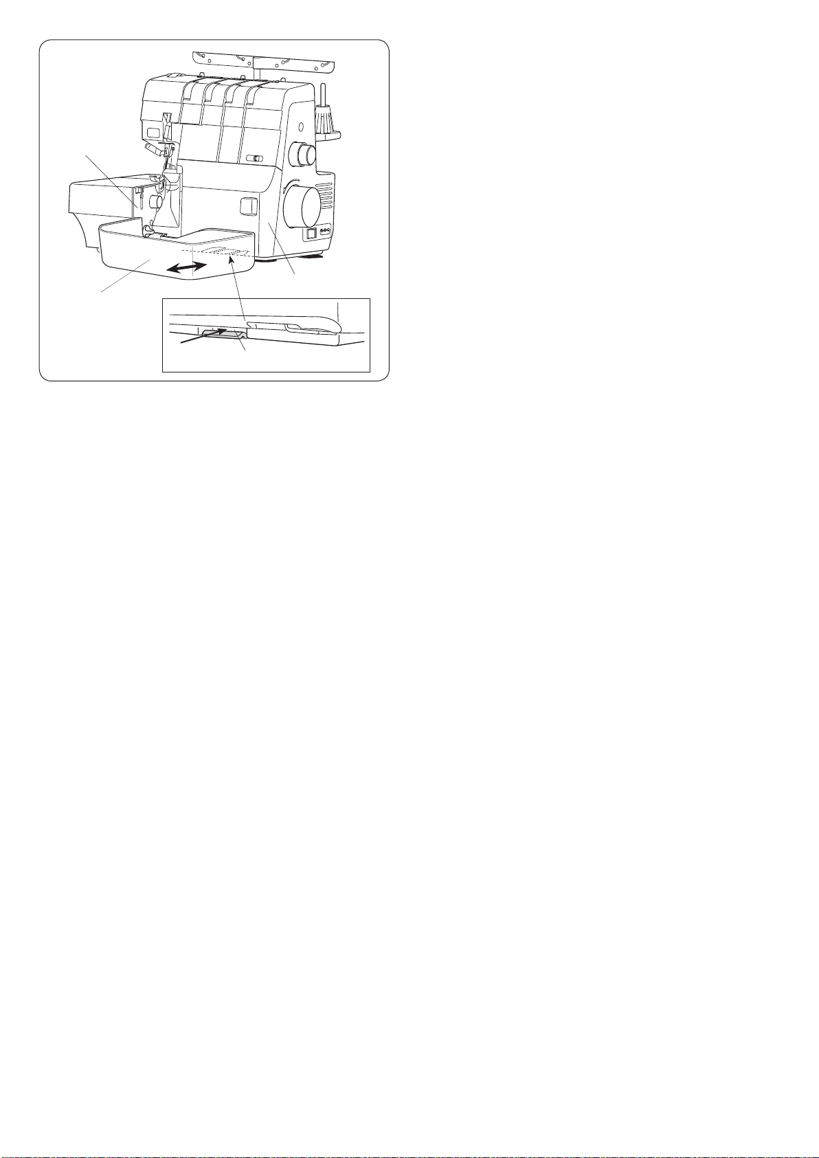
Waste Chip Box.............................................................. 6
GETTING READY TO SEW
Connecting the Power Supply........................................ 7
Before Using Your Machine............................................ 7
Operating Instructions: ................................................... 7
Controlling Sewing Speed.............................................. 7
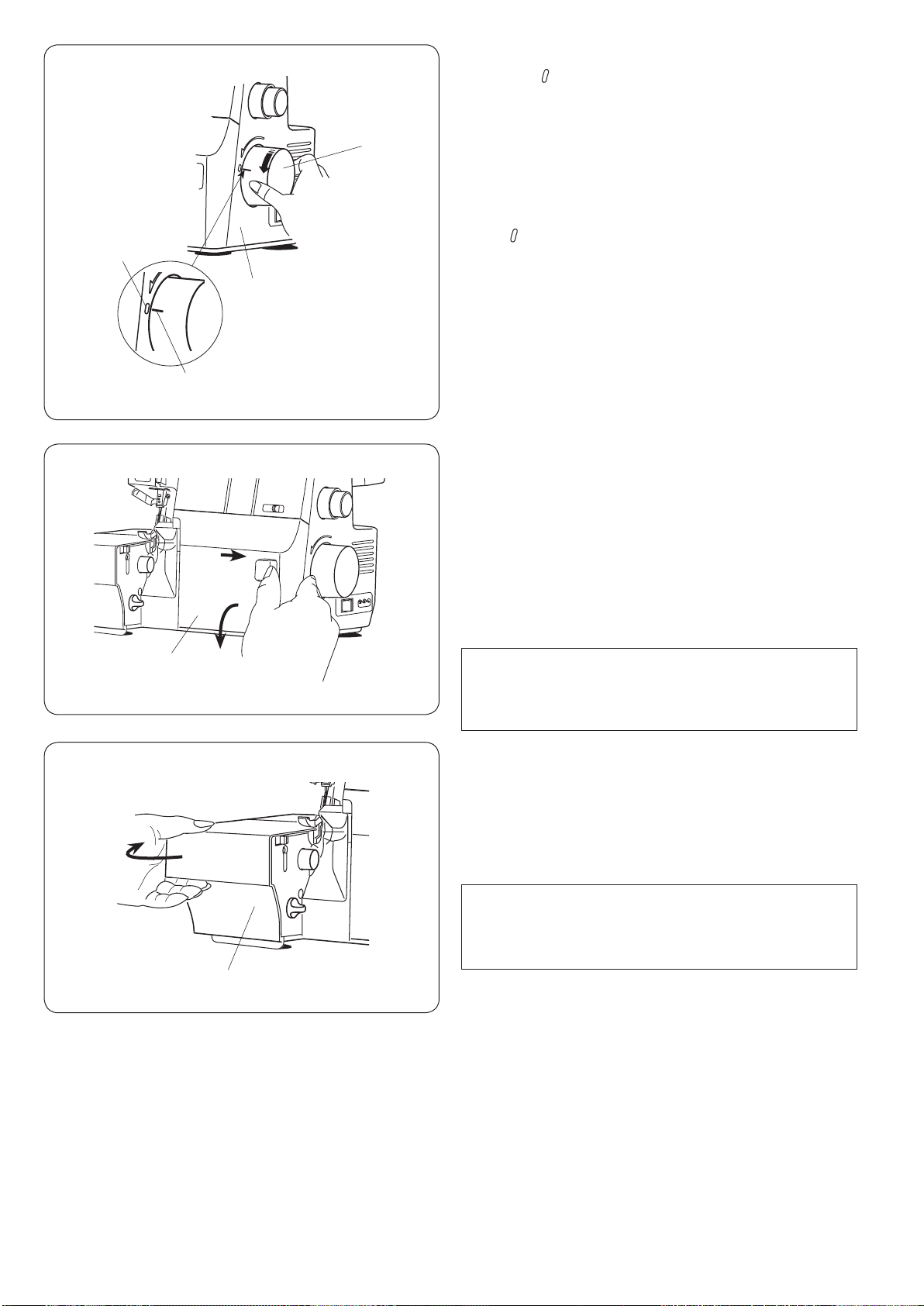
Handwheel ..................................................................... 8
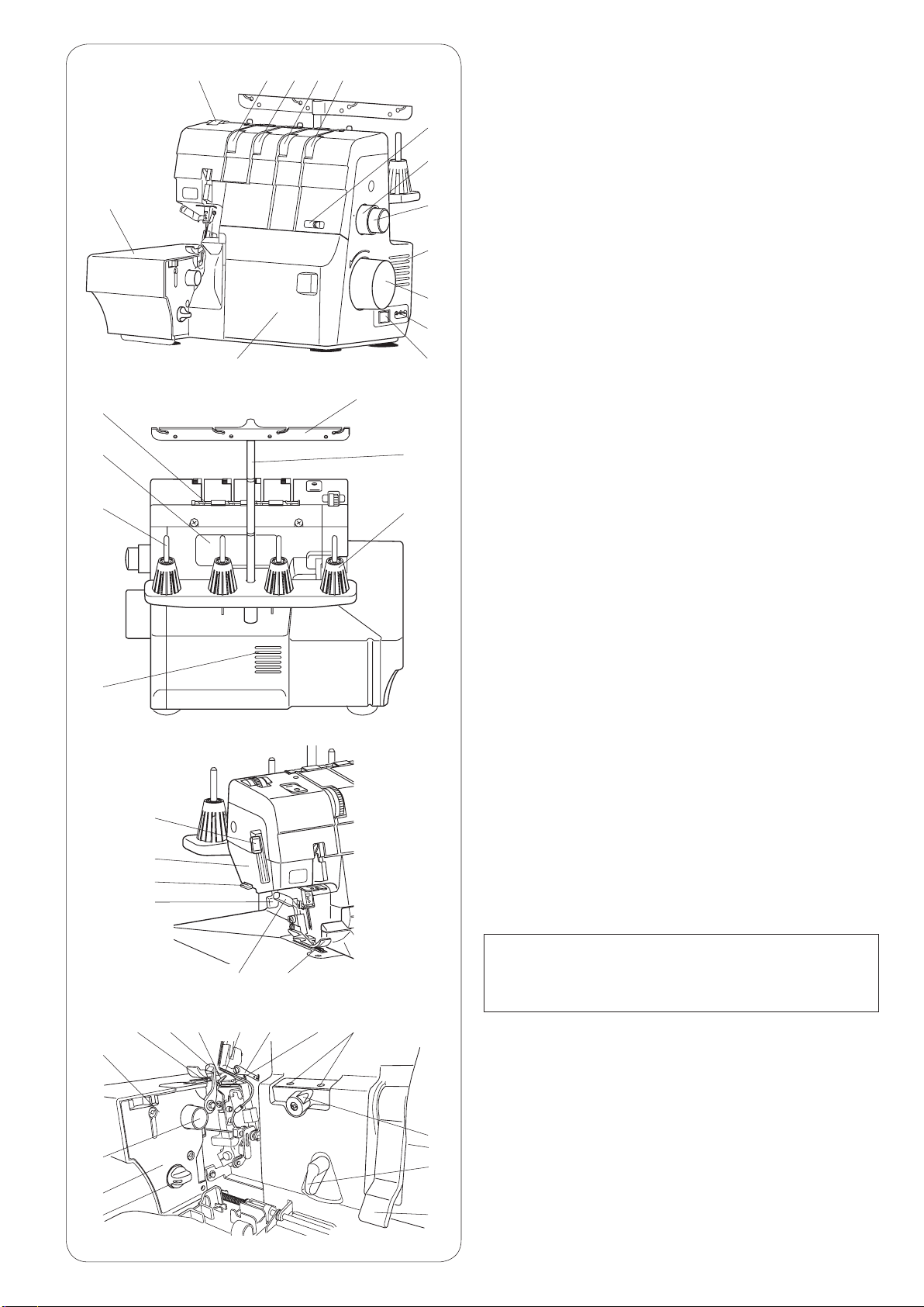
Looper Cover.................................................................. 8
Side Cover...................................................................... 8
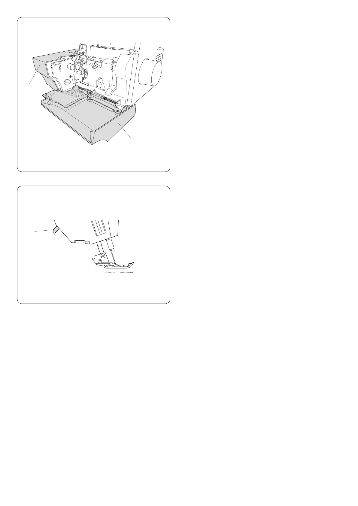
Presser Foot Lifter.......................................................... 9
Removing or Attaching the Presser Foot ....................... 9
Presser Foot Guide Lines............................................... 9
Presser Foot Pressure Dial .......................................... 10
Changing the Needle.................................................... 10
Checking the needle .................................................. 10
Stitch Length Adjustment ..............................................11
Differential Feed Ratio Adjustment ..............................11
How to adjust...............................................................11
Gathering.....................................................................11
To Deactivate or Activate the Upper Knife ................... 12
Cutting Width Adjustment............................................. 12
Chaining Finger Switch Knob Adjustment (Changing to
Standard Serging or Rolled Hemming) ........................ 13
Standard serging ........................................................ 13
Rolled hemming ......................................................... 13
Position of Thread Guide Bar ....................................... 14
Attaching the Spool Holder Cap and Net ..................... 14
MACHINE THREADING
Threading the Machine (4 threads) .............................. 15
Preparation................................................................. 15
Lower looper pre-tension setting slider ...................... 15
Threading the Machine (3 threads) .............................. 16
Threading the Machine (2 threads) .............................. 17
Using the Spreader for Two-thread Serging................. 18
Raising the spreader .................................................. 18
Lowering the spreader................................................ 18
Threading the Lower Looper ................................... 19-21
Threading the Upper Looper ................................... 22-25
Adjusting the looper threader switch lever ................... 23
Threading Loopers with the Looper Threading Wire or
Standard Thread .....................................................26-27
Using the looper threading wire ................................. 26
Using a standard thread............................................. 27
Replacing threaded looper thread.............................. 27
Threading the Right Needle ....................................28-30
Using the needle threader.......................................... 30
Threading the Left Needle....................................... 31-32
Thread and Needle Chart............................................. 33
TEST STITCHING
Starting Sewing ............................................................ 34
Finishing Sewing .......................................................... 34
Sewing Continuously.................................................... 35
Using Guide Lines ........................................................ 35
Securing Ends .............................................................. 36
At the beginning of the seam...................................... 36
At the end of the seam ............................................... 36
Cutting the Seams........................................................ 36
Thread Tension (4 threads) ..................................... 37-38
Thread Tension (3 threads) .......................................... 39
Thread Tension (2 threads) .......................................... 40
ROLLED HEMMING, PICOT EDGING AND NARROW
HEMMING
Tension Dial and Machine Settings According to the
Thread and Fabric ........................................................ 42
For Better Results ........................................................ 43
Thread Tension........................................................44-45
ADVANCED TECHNIQUES
Decorative Overedging................................................. 46
Gathering...................................................................... 47
Pintucking..................................................................... 48
Flatlock ....................................................................49-50
Sewing Corners............................................................ 51
CARE OF YOUR MACHINE
Cleaning the Upper Knife Area .................................... 52
Cleaning the Feed Dog ................................................ 52
Cleaning the Looper Threader Pipe ............................. 53
Replacing the Upper Knife ........................................... 54
Oiling the Machine........................................................ 55
Troubleshooting............................................................ 56
Optional Accessories ................................................... 57
EC DECLARATION OF CONFORMITY ....................... 58

3
NOTE:
Serger/Overlocker/Overlock machine design and
specications are subject to change without prior
notice.
q
w
e
r
t
y
u
i
o
!0
!1
!2
!3
!4
!5
!6
!7
!8
!9
@0
@1
@2
@3
@4
@5
@6
@7
@8
@9
#0
#1
#2
#3
#4
#5
#6
#7
#8
#9
$0
$1
ESSENTIAL PARTS
Names of Parts
Left needle thread tension dial
Right needle thread tension dial
Upper looper thread tension dial
Lower looper thread tension dial
Lower looper pre-tension setting slider
Stitch length dial
Differential feed dial
Ventilation openings
Handwheel
Machine socket
Power switch
Looper cover
Side cover
Presser foot pressure dial
Thread guide
Thread guide bar
Spool holder
Ventilation openings
Spool pin
Hole of rear arm
Top cover thread guide
Needle threader lever
Face plate
Thread cutter
Presser foot lifter
Needle threader switch lever
Presser foot
Upper looper
Spreader
Lower looper
Looper threader hole
Looper selection lever
Looper threader switch lever
Looper threader lever
Upper knife release knob
Looper cover guide
Cutting width adjusting dial
Chaining nger switch knob
Lower knife
Upper knife
Chaining nger
@2
@3
@4
@5
@6 @7
q w e r
t
y
u
i
o
!0
!1
!2
!3
!4
!5
!6
!7
!8
!9
@0
#0$0
@1
#1$1
#2
#3
#4
#5
#6
#7
@8
#8
@9#99

4
Safety Device
This machine is equipped with a safety device that
prevents the machine from starting in the following
conditions:
• The looper cover or the side cover is open
qLooper cover
wSide cover
q
w
e
• The presser foot lifter is raised
ePresser foot lifter
Be sure to close the looper cover and the side cover,
and to lower the presser foot lifter before starting the
machine.

5
q w e
rt y
ui
o
!0
!1
!2 !3
!4 !5
!6 !7
Standard Accessories
*The foot control included may differ from the illustration.
No. Part Name Part No.
1Screwdriver (large) 784810002
2 Screwdriver (small) 647803004
3Double-ended spanner 799807002
4Tweezers 624801001
5
Needle set
(HAx1 SP#11) x 2
(HAx1 SP#14) x 3
784860100
6Net 624806006
7Spool holder cap (Large) 822020503
8Lint brush 802424004
9Oil 741814003
10 Needle holder/spreader pin 799802007
11 Upper knife 799096000
12 Looper threading wire (Looper
threader) 799803008
13 Accessory box 366401400
14 Waste chip box 799801A02
15 Instruction manual 799800201
16 Cover 797608005
17 Foot control*
U.S.A and Canada C-1028
U.K. C-2085-1
Australia C-2065
Continental Europe C-2060
NOTE:
A presentation video with quick-start information is
available for this model and can be downloaded from
our website at www.elna.com/support

6
Waste Chip Box
The waste chip box collects trimmings.
Dispose trimmings after sewing.
To attach:
Sliding the waste chip box along the looper cover guide,
insert the tabs into the slit under the looper cover.
qLooper cover
wWaste chip box
eLooper cover guide
rSlit
To remove:
Pull the waste chip box toward you.
q
w
e
r

7
GETTING READY TO SEW
WARNING
While in operation, always keep your eyes on the
sewing area, and do not touch any moving parts
such as the thread take-up lever, handwheel, knives,
loopers or needles.
Always turn off the power switch and unplug the
machine from the power supply:
- when leaving the machine unattended.
- when attaching or removing parts.
- when cleaning the machine.
Do not place anything on the foot control.
Turn the power switch off.
Insert the machine plug into the machine socket.
Insert the power supply plug into the wall outlet.
Turn the power switch on.
qPower switch
wMachine plug
eMachine socket
rPower supply plug
tWall outlet
yFoot control
Before Using Your Machine
Before using your machine for the rst time, place
a scrap of fabric under the presser foot and run the
machine without thread for a few minutes. Wipe away any
oil which may appear.
Operating Instructions:
The symbol “O” on the switch indicates the “off” position
of the switch.
Foot control model YC-482-J-1 (U.S.A and Canada only)
is used with this machine.
For the U.S.A. and Canada only:
For appliances with a polarized plug (one blade wider
than the other): To reduce the risk of electric shock, this
plug is intended to t in a polarized outlet only one way. If
it still does not t, contact a qualied electrician to install
the proper outlet. Do not modify the plug in any way.
Controlling Sewing Speed
Depress the foot control to start the machine.
The further down you press on the foot control, the faster
the machine runs.
qFoot control
w
e
q
r
t
y
q
NOTE:
A presentation video with quick-start information is
available for this model and can be downloaded from
our website at www.elna.com/support
Connecting the Power Supply

8
Handwheel
Match the “ ” mark of the belt cover with the “–” mark
of the handwheel when threading needles, adjusting
the chaining nger switch knob or raising/lowering the
spreader.
Always turn the handwheel toward you
(counterclockwise).
qHandwheel
wBelt cover
e“ ” mark
r“–” mark
Looper Cover
To open:
Hold the looper cover as illustrated and slide it to the right
as far as it will go.
Pull the looper cover toward you to open it.
qLooper cover
To close:
Push the looper cover back up. The looper cover snaps
into position automatically.
Side Cover
To open:
Pull the side cover to the left.
qSide cover
To close:
Push the side cover to the right.
q
q
q
w
e
r
NOTE:
Always close the looper cover when the machine is
in use. You cannot run the machine with the looper
cover open.
NOTE:
Always close the side cover when the machine is in
use. You cannot run the machine with the side cover
open.

9
Removing or Attaching the Presser Foot
CAUTION:
Turn OFF the power switch before removing or
attaching the foot.
To remove:
zRaise the presser foot lifter.
xRaise the needle to its highest position by turning the
handwheel counterclockwise.
q Needle
w Presser foot lifter
cPress the lever located on the back of the foot holder.
The presser foot will drop off.
e Presser foot
r Lever
To attach:
zPlace the presser foot so that the pin on the foot is
just under the groove on the foot holder.
Lower the foot holder to lock the foot into place.
xRaise the presser foot lifter.
Make sure that the presser foot is secured.
q Presser foot
w Groove
e Pin
Presser Foot Guide Lines
The guide lines on the toe of the presser foot are marked
with two needle positions.
The left guide line is marked at the left needle position.
The right guide line is marked at the right needle position.
q Left needle position
w Right needle position
z
z
x
x
c
q
w
e
r
q
q
e
w
w
q
e
w
Presser Foot Lifter
The presser foot lifter raises and lowers the presser foot.
Raise the presser foot lifter before you thread the
machine.
Always lower the presser foot lifer when you start sewing.
qPresser foot
wPresser foot lifter
NOTE:
Tension disks open when the presser foot lifter is
raised. Raise presser foot lifter when you pass the
thread between the tension disks.
eTension disks

10
CAUTION
Turn OFF the power switch before changing the
needle.
z Raise the needle to its highest position by turning the
handwheel counterclockwise.
x Insert the needle attached to the machine into the
hole of the needle holder.
q Needle holder
c Loosen the needle clamp screw with the screwdriver
(small) and remove the needle.
w Small screwdriver
e Needle clamp screw
v Insert a new needle into the needle holder with the flat
side to the rear.
r Hole of needle holder
t Flat side
b Insert the needle into the needle clamp and push it up
as far as it will go.
n The top of the right needle should touches the bottom
of the needle bar and the top of the left needle should
touches the edge of the needle bar.
y Left needle
u Right needle
i Edge of needle bar
o Bottom of needle bar
m Firmly tighten the needle clamp screw with the
screwdriver (small) while holding the holder in place.
Pull the needle holder down to remove the needle.
Checking the needle
To see if the needle is in good condition, place the at
side of the needle onto something at (needle plate, glass
etc.). The gap between the needle and the at surface
should be consistent. Never use a bent or blunt needle.
q Flat side
w Something at
e Gap
Changing the Needle
* Use an HA-1 SP #14 or #11 needle.
* An HA-1 SP #14 needle is set on the machine.
q
w
q
e
q
w
e
r
yu
i
o
w
ew
q
r
t
q
x c b m
n
Presser Foot Pressure Dial
Foot pressure can be adjusted by turning the presser foot
pressure dial.
Set the pressure to “N” for ordinary fabrics.
Turn the dial toward you for light weight fabrics .
Turn the dial away from you for heavy weight fabrics.
qPresser foot pressure dial
w Setting mark
e To increase
r To decrease
You do not need to adjust the presser foot pressure for
normal sewng.
After making an adjustment, sew and check the pressure.
v
NOTE:
Partially tighten the needle clamp screw on the side
that is not being used to prevent losing the screw.

11
Stitch Length Adjustment
To adjust the stitch length, turn the stitch length dial.
The larger the number, the longer the stitch.
q Stitch length dial
w Setting mark
The standard stitch length setting for serging stitch is “3”
(approximately 3 mm).
The dial clicks when you turn the dial to 3.
The stitch length can be adjusted while sewing.
Differential Feed Ratio Adjustment
Adjust the differential feed ratio when sewing fabrics that
tend to stretch or pucker.
The differential feed ratio can be altered by turning the
differential feed dial.
The number on the dial indicates the ratio between the
main and the sub feed motion.
q Differential feed dial
w Setting mark
The neutral position of the differential feed dial is 1.0.
The differential feed dial clicks when you turn the dial at
1.0.
Set the dial to a number larger than 1.0 to sew while
gathering the fabric.
Set the dial to a number smaller than 1.0 to sew while
stretching the fabric.
How to adjust
If the sewn fabric stretches, turn the dial counterclockwise
(toward 2.0).
If the sewn fabric is gathered, turn the dial clockwise
(toward 0.5).
q Stretched
w Gathered
q
q
q
w
w
w
NOTE:
• The stitch length can be adjusted from 1 to 5 mm.
• Position “R” is for rolled hemming and narrow
hemming (approximately 1.5 mm).
Gathering
You can sew gathering with a single layer of light weight
or medium weight fabric.
Set the differential feed dial to 2.0.
Set the stitch length dial to 4.

12
Deactivate the upper knife for atlock, pintucking, etc.
q Upper knife release knob
w Upper knife
Cutting Width Adjustment
When the cutting width is too narrow or too wide for
the seam width, adjust it by turning the cutting width
adjusting dial.
q Cutting width adjusting dial
Turn the cutting width adjusting dial to get the desired
position of the lower knife.
When the lower knife is set to the standard position, the
right edge of the lower knife is aligned with the guide line
on the needle plate.
w Standard position
e Lower knife
r Guide on the needle plate
t Edge of fabric
If the cutting width is too narrow y, turn the cutting width
adjusting dial clockwise (to the direction of A).
The lower knife moves to right.
If the cutting width is too wide u, turn the cutting width
adjusting dial counterclockwise (to the direction of B).
The lower knife moves to left.
Sew and check the cutting width.
(A)
(B)
(A)
(B)
A
B
q
w
e
e
CAUTION
Turn the power switch OFF before adjusting the
cutting width.
q
we
r
tt
y u
To deactivate:
While pressing the upper knife release knob (A), turn the
knob clockwise (B) and set the setting mark to [ ].
e Setting mark
To activate:
While pressing the upper knife release knob (A), turn the
knob clockwise (B) and set the setting mark to [ ].
To Deactivate or Activate the Upper Knife
CAUTION
• Turn the power switch OFF before deactivating or
activating the upper knife.
• Do not cut anything else with the upper knife other
than fabric, causing the upper knife to break.

13
Chaining Finger Switch Knob Adjustment
(Changing to Standard Serging or Rolled
Hemming)
Standard serging
The chaining finger is located beside the needle plate.
Turn the chaining finger switch knob to “S” for standard
serging.
q Chaining nger
w Chaining nger switch knob
Rolled hemming
Turn the chaining finger switch knob to “R” for rolled for
hemming, picot edging or narrow hemming sewing.
q Chaining nger
w Chaining nger switch knob
CAUTION
Turn the power switch OFF before adjusting the
chaining nger switch knob.
q
q
w
w
q
w
e
The chaining nger switch knob is connected to the
chaining nger.
The chaining nger slides back and forth when you set
the chaining nger switch knob to “S” or “R”.
Turn the handwheel toward you to match the “ ” mark on
the belt cover with the “–” mark on the handwheel.
q Handwheel
w “ ” mark
e “–” mark

14
Position of Thread Guide Bar
Pull the thread guide bar up as far as it will go.
q Thread guide bar
Turn the thread guide bar until it snaps into place.
Be sure to snap both stoppers into places.
The thread guide bar is placed right above the spool pins
as shown.
w Thread guide
e Stopper
r Spool pin
Attaching the Spool Holder Cap and Net
When you use a small thread spool, pull out the spool
holder from the spool pin.
Place the spool with its slit side up, and put the spool
holder cap on top of it.
q Spool holder
w Spool pin
e Spool holder cap
If the thread slips down from the spool during threading
and/or sewing, put a net on the spool as illustrated to
prevent jamming.
r Net
q
w
e
r
q
w
e
q
r
t* Firmly insert the spool holder into the spool.
q Spool holder
t Spool

15
MACHINE THREADING
Threading the Machine (4 threads)
q w e r
t
CAUTION
Turn the power switch OFF before threading the
machine.
NOTE:
• The looper threader can be used with standard
threads #60 - #100.
• The looper threader cannot be used with special
threads, such as wooly nylon, gold thread, etc.
For threading, refer to “Using the looper threading
wire”
(page 26) or “Using a standard thread” (page 27).
• For general sewing, standard threads #60 - #100
are used as needle thread.
• Do not use poor quality thread.
Preparation
Pull the thread guide bar up as far as it will go, and set
the spools (refer to page 14).
Raise the presser foot lifter (refer to page 9).
Open the looper cover (refer to page 8).
Lower looper pre-tension setting slider
The lower looper pre-tension setting slider adjusts the
lower looper tension.
Set the lower looper pre-tension setting slider to STD. to
normal sewing.
t Lower looper pre-tension setting slider
* Set the lower looper pre-tension setting slider to
STD.when threading.
The left illustration shows the completed threading
conditions.
Refer to pages 19-21 for threading the lower looper.
Refer to pages 22-24 for threading the upper looper.
Refer to pages 28-30 for threading the right needle.
Refer to pages 31-32 for threading the left needle.
q Left needle thread
w Right needle thread
e Upper looper thread
r Lower looper thread

16
NOTE:
Partially tighten the needle clamp screw on the side
that is not being used to prevent losing the screw (refer
to page 10).
Threading the Machine (3 threads)
You can sew three-thread serging using the right needle
or the left needle.
Using the needle on the right only
(for regular three-thread serging)
When you use the right needle, the standard sewing
width is 3.5 mm.
The left illustration shows the completed threading
conditions.
Refer to pages 28-29 for details on how to thread the
right needle and page 30 for details on how to use the
needle threader.
CAUTION
Turn the power switch OFF before threading the
machine.
Using the needle on the left only
(for wide three-thread serging)
When you use the left needle, the standard sewing width
is 5.7 mm.
The left illustration shows the completed threading
conditions.
Refer to pages 31-32 for details on how to thread the left
needle and page 30 for details on how to use the needle
threader.
NOTE:
Partially tighten the needle clamp screw on the side
that is not being used to prevent losing the screw (refer
to page 10).

17
Threading the Machine (2 threads)
You can sew two-thread serging using the right needle or
the left needle.
Use the lower looper and the spreader.
Refer to page 18 for details on how to raise and lower the
spreader.
Using the needle on the right only
(for regular two-thread serging)
When you use the right needle, the standard sewing
width is 3.5 mm.
The left illustration shows the completed threading
conditions.
Refer to pages 28-29 for details on how to thread the
right needle and page 30 for details on how to use the
needle threader.
CAUTION
Turn the power switch OFF before threading the
machine.
Using the needle on the left only
(for wide two-thread serging)
When you use the left needle, the standard sewing width
is 5.7 mm.
The left illustration shows the completed threading
conditions.
Refer to pages 31-32 for details on how to thread the left
needle and page 30 for details on how to use the needle
threader.
NOTE:
Partially tighten the needle clamp screw on the side
that is not being used to prevent losing the screw (refer
to page 10).
NOTE:
Partially tighten the needle clamp screw on the side
that is not being used to prevent losing the screw (refer
to page 10).

18
Using the Spreader for Two-thread Serging
Use the spreader pin (needle holder) to raise or lower the
spreader.
Raising the spreader
zTurn the handwheel toward you to match the “ ” mark
on the belt cover with the “–” mark on the handwheel.
Raise the needle.
q Handwheel
w “ ” mark
e “–” mark
xInsert the spreader pin into the small hole in the
spreader and turn the spreader pin counterclockwise
until the hook comes to the tip of the upper looper.
(Slightly turn the needle holder so that the needle
holder does not touch the upper knife.)
r Spreader pin
t Hook
y Small hole
u Spreader
i Upper looper
o Upper knife
cSlightly push the spreader pin so that the hook goes
behind the bulge of the upper looper and into the hole
in the upper looper.
!0 Bulge
vRemove the spreader pin from the spreader.
!1 Hole of upper looper
(Upper view of the upper looper)
(Rear view of the upper looper)
q
w
e
r
r
t
t
t
y
ui
i
i
o
!0
!0
!1
z
z
x
x
c
c
v
CAUTION
Turn the power switch OFF before raising or lowering
the spreader.
Lowering the spreader
zInsert the spreader pin into the small hole in the
spreader.
Slightly push the spreader and turn it clockwise so
that the hook comes over the bulge.
(Slightly turn the needle holder so that the needle
holder does not touch the upper knife.)
r Spreader pin
i Upper looper
!0 Bulge
xTurn the spreader clockwise to the original position
(until the spreader clicks).
cRemove the spreader pin from the spreader.
CorrectWrong
Other manuals for eXtend 864air
1
Table of contents
Other ELNA Sewing Machine manuals

ELNA
ELNA Elnita ec60 User manual

ELNA
ELNA eXcellence 730 PRO User manual

ELNA
ELNA Plana Star de Luxe CI. User manual

ELNA
ELNA eXpressive920 User manual

ELNA
ELNA eXcellence 720 User manual

ELNA
ELNA Xquisit II User manual

ELNA
ELNA eXperience 520 User manual

ELNA
ELNA eXtend 864air User manual

ELNA
ELNA 8600 User manual

ELNA
ELNA Supermatic User manual