Powers HydroGuard 1430 Series User manual

Water Tempering Solutions to 225 GPM
1430 Series Two-Valve Hi/Lo

Description
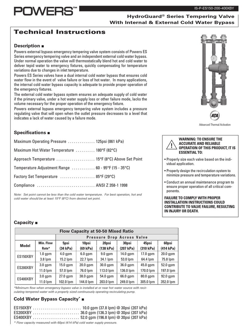
Powers' HydroGuard Series 1430 High Capacity Systems are fully assembled, and factory tested, designed to provide safe water
throughout commercial and institutional facilities. HydroGuard Series 1430 high capacity systems consist of HydroGuard 434
and HydroGuard Series 1430 thermostatic tempering valves mounted on heavy-duty struts which utilize paraffin-based actuation
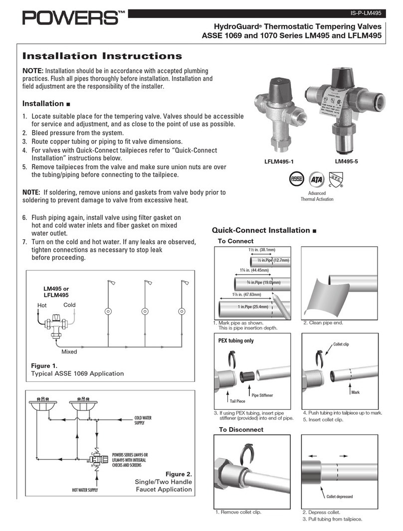
technology to sense and adjust outlet temperature. Each system also includes a PRV (with Hi/Lo), ball valves, thermometers,
pressure/temperature gauges and Powers’ triple-duty check stops. Optional equipment includes cabinets and /or Powers'
AquaSentry2 high temperature alarm system.
Operations
Two-valve supply fixtures feature a low capacity valve that works in parallel with a high capacity valve. During low demand, the low
capacity valve handles the load requirements. As the load demand is increased, the pressure reducing valve, which is set at a cer-
tain pressure differential, will open and allow flow through the high capacity valve to assist the low capacity valve in meeting the
increased load requirements.
Specifications
Table 1 — Flow Capacity When Tested To ASSE 1017 Standard †
1
Form PS/TI 2-Valve HCS Series 1430 v4 0530
Min. Flow
Model to ASSE Pressure Drop Across Valve
1017
5 psi 10 psi 20 psi 30 psi 45 psi 60 psi
(34 kpa) (69 kpa) (138 kpa) (207 kpa) (310 kpa) (414 kpa)
1432DV 6.5 gpm 46.0 gpm 63.0 gpm 93.0 gpm 113.0 gpm 140.0 gpm 163.0 gpm
(25 lpm) (174 lpm) (238 lpm) (352 lpm) (428 lpm) (530 lpm) (617 lpm)
1432HL 1.5 gpm 54.0 gpm 73.0 gpm 109.0 gpm 134.0 gpm 165.0 gpm 192.0 gpm
(6 lpm) (204 lpm) (276 lpm) (413 lpm) (507 lpm) (625 lpm) (727 lpm)
1434DV 10.0 gpm 64.0 gpm 90.0 gpm 132.0 gpm 160.0 gpm 200.0 gpm 234.0 gpm
(38 lpm) (242 lpm) (341 lpm) (500 lpm) (606 lpm) (757 lpm) (886 lpm)
1434HL 5.0 gpm 72.0 gpm 100.0 gpm 148.0 gpm 181.0 gpm 225.0 gpm 263.0 gpm
(19 lpm) (273 lpm) (379 lpm) (560 lpm) (685 lpm) (852 lpm) (996 lpm)
Maximum Pressure Differential 100 psi (689 kpa)
Maximum Static Pressure 125 psi (862 kpa)
Maximum Hot Water Temperature 200°F (93°C)
Minimum flow* 0.5 gpm (2.0 lpm)
Minimum flow at which valve will control to ASSE 1017 requirements.
1432DV 6.5 gpm (25 lpm)
1432HL 1.5 gpm (6 lpm)
1434DV 10.0 gpm (38 lpm)
1434HL 5.0 gpm (19 lpm)
Approach Temperature 15°F (8°C)
Temperature Adjustment Range 40° - 160°F (4° - 71°C)
*Minimum flow when Two-Valve High Capacity Systems are installed at or near hot water source with re-circulated
tempered water with a properly sized continuously operating re-circulating pump.
† ASSE 1017 Section 3-2

Dimensions & Legends
2
Form PS/TI 2-Valve HCS Series 1430 v4 0530
Dual Valve System (DV)
VALVE INLETS OUTLET PRV
1432DV 1-1/2” (38 mm) 2” (51 mm) —
1432HL 1-1/2” (38 mm) 2” (51 mm) 2” (51 mm)
1434DV 2” (51 mm) 2-1/2” (64 mm) —
1434HL 2” (51 mm) 2-1/2” (64 mm) 2” (51 mm)
Hi/Lo System (HL)

Piping Diagrams
Diagram 1. Low temperature hot water recirculation diagram.
Diagram 2. Low temperature hot water recirculation diagram with separate high temperature hot water recirculation.
3
Form PS/TI 2-Valve HCS Series 1430 v4 0530

Prior to Installation
1. Flush all piping thoroughly before installing.
2. Make sure all ball valve handles are in “OFF” position.
3. In order to make any temperature adjustment to the valves, you must open end-of-line fixtures to ensure you have
adequate flow across the valve.
4. Use a thermometer at the showerhead or install an in-line thermometer at the point-of-use.
5. Typical piping diagrams are shown on page 4, for other alternatives or special circumstances,
contact Powers’ Technical Support Department at 1.800.669.5430.
Set Up Procedure
You must follow these procedures in order to properly adjust your High Capacity System. You need flow greater than the minimum
shown in table 1 across the valve in order to set a maximum temperature.
1. Close the ball valve on the outlet of the low flow valve.
2. Open the ball valve at the discharge of the high flow valve.
3. Open enough fixtures to meet the minimum flow requirement as per
table 1.
4. Set valve temperature (refer to enclosed TI if required).
5. For “HL” only. For “DV” skip to #6. Set the PRV as follow for a 15 psi
differential.
a) Loosen the locknut at the top of the PRV. This must be all the way
out or you will be limiting the range of the adjustment.
b) Adjust the PRV so the outlet pressure gauge (top) reads 15 psi less
than the supply pressure gauge (bottom). Turning the adjustment nut
clockwise will increase outlet pressure (decrease the differential)
across the PRV (allowing the PRV to open sooner). Turning the adjust
ment nut counter-clockwise will decrease outlet pressure (increase
the differential) across the PRV (allowing the PRV to open later).
6. Close the ball valve at the discharge of the high flow valve.
7. Open the ball valve on the outlet of the low flow valve.
8. Open enough fixtures to meet the minimum flow requirement as per table 1.
9. Set the temperature for the low flow valve (refer to TI if required).
10. Open the ball valve at the discharge of high flow valve.
11. Open additional fixtures to develop a 20 psi differential between the supply and outlet pressure gauges (table 1).
12. Verify temperature remains at set point.
13. Gradually start to close fixtures to verify that the temperature remain constant through the full range of flow.
14. For any problem, refer to troubleshooting section of the document or contact Powers’ Application Department.
Troubleshooting
Outlet temperature is too hot with low flow:
1) The temperature of the low flow valve was not properly set. Refer to set up procedure and reset the maximum
temperature of the low flow valve.
2) The thermal actuator of the low flow valve is not working properly. Test and replace accordingly to the TI 1430
technical instructions enclosed.
Outlet temperature is too hot with a high flow:
1) The temperature of a high flow valve was not properly set. Refer to set up procedure and reset the maximum
temperature of the high flow valve.
2) The thermal actuator of the high flow valve is not working properly. Test and replace accordingly to the TI 430
technical instructions enclosed.
4
Form PS/TI 2-Valve HCS Series 1430 v4 0530
Installation and Troubleshooting
5
Form PS/TI 2-Valve HCS Series 1430 v4 0530
Troubleshooting Cont’d
Outlet temperature stable, but creep high overnight:
1) Recirculation lines are not properly plumbed. Refer to piping diagram on page 4.
2) The PRV opening too soon. Refer to set up procedure and reset the differential across the PRV.
3) The return pump runs constantly. Install an Aquastat on the return pump. Refer to piping diagram on page 4.
Outlet temperature too low on low and high flow:
1) The hot water temperature is too low. You must have a supply temperature of at least 15º F (8º C) higher than the
set temperature. Readjust the hot water supply.
2) The check stops on the hot side of the valve are not fully open, or may be stuck due to debris. Open and clean
check stops and screen.
3) The temperature has not been set properly on the small and/or large valve. Refer to set up procedure and reset
the valves.
Outlet flow drops off:
1) The differential across the PRV is set too high, so the high flow valve begins controlling the system too late,
and starves the system. Refer the set up procedure and decrease the differential across PRV.
2) The check stops on the high flow valves are not fully open or are stuck due to liming. Open and clean check stops.
3) The system pressure varies by more than 50% of the inlet supply pressure.
Outlet temperature cycles between hot and cold:
1) The differential across the PRV is set too low, so the high flow valve begins controlling the system too early, and
therefore cycles (hunt for the set point). Refer the set up procedure and increase the differential across PRV.
Refer the set up procedure and decrease the differential across PRV.
2) The system pressure varies by more than 50% of the inlet supply pressure.
Preventive Maintenance
Thermostatic water mixing valves are control devices which must be cleaned and maintained on a regular basis.
1) Before servicing check stops or piping, turn off the water upstream. At least every twelve (12) months open up the
check stops and check for the free movement of the poppet.
2) Before servicing the valve, turn off the water supply upstream or close the check stops. To close the
check stops, turn the adjusting screw clockwise.
3) When opening check stops after servicing, do not over adjust; make sure the center of the stop is still pushed in.
4) Every three (3) months, check the maximum temperature adjustments.
Caution:
Any changes in supply condition could effect the outlet water temperature. Check and adjust the valves
accordingly to prevent injury to the users.
5) Every twelve (12) months, remove the valve bonnets and check the internal components for freedom of movement.

Parts Kits
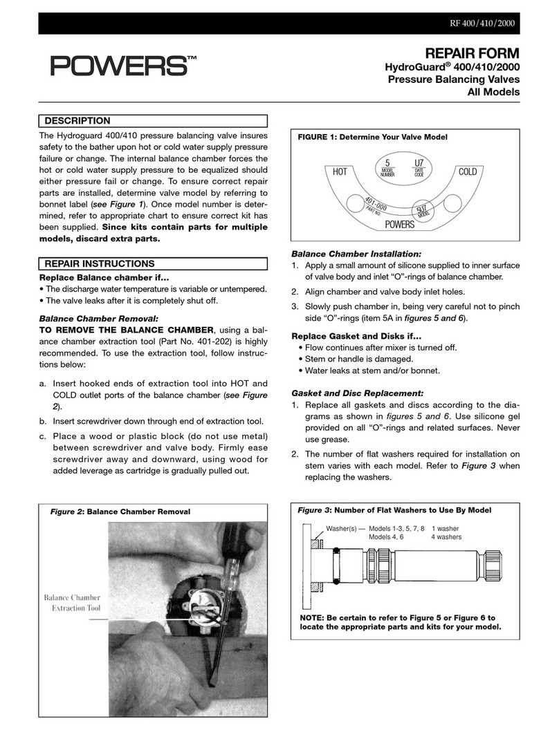
REPAIR KITS for 434
REPAIR KITS for 1430
6
Form PS/TI 2-Valve HCS Series 1430 v4 0530
PART DESCRIPTION REPAIR KIT INCLUDES: 434 Part No.
Thermal Actuator 1, 2, 4, 13, AND 15 390-066
Strainer Replacement 7, 8, 9, and 10 230-136
Check stop Replacement 7, 8, 10, 11, and 12 230-137
Gasket and Disc Replacement 1, 2A, 4, 6, 7, 8, 10, and 12 390-306
Mixing Valve Replacement 3, 4, 5, and 6 390-070
Strainer and Check stop Repair Kits contain parts for one (1) pair.
Repair Kits containing “O” Rings include Silicone gel for use on “O” Rings during installation.
PART DESCRIPTION REPAIR KIT INCLUDES: 1432 1434
Hi-Lo Motor Replacement Kit 13 and 2 390-500 390-543
Strainer Replacement 7, 8, 9, and 10 230-134 230-136
Check stop Replacement 7, 8, 10, 11, and 12 230-135 230-137
Gasket and Disc Replacement 1, 4, 6, 7, 8, 10, and 12 390-298 390-306
Mixing Valve Replacement 1, 3, 4, 5, and 6 390-068 390-070
Strainer and Check stop Repair Kits contain parts for one (1) pair.
Repair Kits containing “O” Rings include silicone gel for use on “O” Rings during installation

Ordering Information
Typical Specification
CALIFORNIA PROPOSITION 65 WARNING
WARNING: This product contains chemicals known to the
State of California to cause cancer and birth defects or other
reproductive harm. (California law requires this warning to be
given to customers in the State of California.)
For more information: www.wattsind.com/prop65
Engineering Approval
Project _____________________________
Contractor___________________________
Architect/Engineer ____________________
Model No.
Valve# Inlet Outlet Order Code
(inches) (inches)
1432/1434 1-1/2 2.0 1432DV
434/1432 1-1/2 2.0 1432HL
1434/1434 2.0 2-1/2 1434DV
434/1434 2.0 2-1/2 1434HL
Piping/Finish
Rough Bronze A
Polished Chrome (Rough Chrome Piping/ B
Polished Chrome Valve)
Cabinets
Exposed, No Cabinet M
Stainless Steel, Recessed N
Stainless Steel, Wall Mount Q
Painted Steel, Recessed R
Painted Steel, Wall Mount U
Alarm (not factory installed)*
None 0
AquaSentry2** for 1432DV or 1432HL 6
AquaSentry2** for 1434DV or 1434HL 7
* Mounting requirements varied based on individual installation.
** Includes control module, sensor, electrical box, transformer, solenoid, shock absorber, and 25 feet of station cable.
High capacity water temperature control system will be pre-assembled and pre-tested and mount-
ed on heavy-duty metal struts for stability. The system includes two thermostatic valves capable
of maintaining water temperature within the performance requirements of ASSE 1017 and CSA
B125. Valves will be ASSE listed and CSA certified. Valves will feature paraffin-based actuation
technology with temperature adjustment from 40° F (4° C) - 160° F (71° C) with a 15° F (8° C)
approach temperataure. Temperature adjustment will be vandal resistant and feature a locking
mechanism.
Valves will be of bronze body construction and feature triple-duty check stops with screens to
filter out debris. The system will include a PRV (“HL” series only), ball valves, pressure gauges and
thermometers. The system will be a Powers’ Series HydroGuard 1430HL or HydroGuard 1430DV.
Any alternate must have a written approval prior to bidding.
© 2004 Powers, a division of Watts Water Technologies, Inc.
USA Phone: 800-669-5430 • Fax: 847-824-0627 • Canada Phone: 1.888.208.8927 • Fax: 1.888.882.1979
www.powerscontrols.com Printed in U.S.A.
Form PS/TI 2-Valve HCS 1430 v4 0530 EDP# 6512268
This manual suits for next models
4
Table of contents
Other Powers Control Unit manuals

Powers
Powers HydroGuard LFLM490 User manual

Powers
Powers HydroGuard LM495 Series User manual

Powers
Powers LFLM49 Series User manual

Powers
Powers Hydroguard 410 5 Owner's manual

Powers
Powers Biltmore 900 Series Owner's manual

Powers
Powers IntelliStation Jr User manual

Powers
Powers LFLM490-10 User manual

Powers
Powers HydroGuard XP Series LFSH1430 Owner's manual

Powers
Powers HYDROGUARD MM430 Series Owner's manual

Powers
Powers HydroGuard ES150XBY Owner's manual