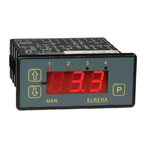
ELREHA MSR eco 3140 User manual

Brief Description / Applications
• Suction Pressure Controller and/or High Pressure Controller,
configurable for:
- Standard Compressors
- Compressors with CRII-System Control Stages
- Condensation High Pressure Control
• For up to 8 Suction Pressure Stages respective High Pressure Stages usable
• For use as a single controller or in a network
• Direct connection of up to 64 Cold Storage Controllers,
Data Exchange for Energy Optimization
• 4 Sensor-, 2 Pressure Transmitter- , 4 Digital Inputs,
5 Relay Outputs (2 Relays, 3 SSR-Relays), Analogue Output
• Capable of handling up to 4 additional stages.
(When used in conjunction with Expansion Module BMR 3002).
• For Single- and Multi-Stage Loads
• Peak Load Limitation, Suction Pressure Shifting
• Automatic Stage Sequencing
• Fixed or Autoadaptive Delay Times for Switching Frequency Optimization
• Capturing of Machine Feedback Signals and Plant Errors
• Analogue Output for P/PI-Control
• In-/Outputs configurable
• Manual Operation of all Machines
• Night Operation via internal clock
Please note Safety Instructions
on page 10 !
Operating / Operating Elements
ELEKTRONISCHE REGELUNGEN GMBH
Actual
Values
Page
Setpoint
Page
Suction
Pressure
increase
values
decrease
values
Attention
The displayed setpoint
is active
Some functions may not be available on devices
with older software versions.
1 2 3 4
EVP
ELREHA
P
Convenient 3 key control for all functions clearly appear on a 7 segment LED
display. 4 symbols to the right indicate active control function(s). (Relay status
is indicated separately on „Actual Page“).
programming key
LED blinking = Alarm
The current states of the Digital Inputs, the Relay Outputs and the Data
Transmission can be read on the Actual Values Page at L98 and L99.
Programming
The MSR eco parameters are simple to access, view and change. During
normal operation, or if no key is pressed for at least 3 minutes, the MSR eco
will display the following:
1st priority: current failure display (blinking)
2nd priority: operation status display (ex. „oFF“)
3rd priority: selected „permanent parameter“ display
Selecting and Changing of Parameters
Key Action
P(> 2 sec.) ....Page name will be displayed
.................Select desired page
P..................Enter the page
.................Select parameter
P..................Prepare programming. Enter access code if necessary
.................Change value.
If you hold the key, the values change continuously
P..................Confirm programming
P(> 2 sec.) ....Page name will be displayed again
Access Protection
All adjustable parameters/set-points are protected by an access code.
They are divided into 3 groups or levels with 3 operator codes.
An access code will be required to change an adjustable parameter, (see
parameter listing).To change an adjustable parameter that requires an access
code, begin by pressing the „P“ key.:
The screen will display C00, prompting the user for access
code entry.
The Access Codes are divided into 3 access levels, (OEM, Technician, and
Customer Codes).
- OEM Code „oem“: Month + Hour + 20
The OEM Code grants access to all adjustable parameters on the
device.
- Technician Code „tec“ : 88
The Technician Code grants access only to „Technician“ and „Customer“
assigned adjustable parameters.
- Customer Code „---“ : no access code required.
The Customer Code grants access only to „Customer“ assigned
adjustable parameters.
If no key has been pressed for 3 minutes, the operator code must be
re-entered.
(00
Parameter Pages
P
(L)
> 2 sec.
P
(r)
(P)
Mode
Page
(A)
Address
Page
(h)
Assign-
ment
Page
L01
r01
P10
A01
h01
1st. Parameter
on the
P
P
P
P
(d)
d01
PSetpoint
Page
High
Pressure
Technical Manual 5311437-03/02e/01
Stage Controller
2018-06-25, tkd/jr
from Software Vers. 2.04
MSR eco 3140

Technical Manual Stage Controller MSR eco 3140Page 2
MSR eco
System Overview
Accessories
- Temperature sensor TF 501, quantity depends on application
- Pressure Transmitter with 4...20mA Output
Technical Data
Supply Voltage.............................230V 50-60Hz, max. 9 VA (controller only)
Ambient Temperature.......................................................................0...+50°C
Max. Air Humidity....................................................85% r.H., not condensing
Inputs .............................................. 4x Temperature Sensors, TF 201 (PTC)
or TF 501 (Pt 1000), or customer specific probes
2x Pressure Transmitter 4-20mA DC (scalable), Ri= 100 Ohm
Measuring ranges TF 501 (Pt1000).................... -100°C...+100°C
of the probe inputs TF 201 (PTC, 2 kΩ at 25°C)....... -50°C...+100°C
So1 ......................................... -40°C...+25°C
So2 ......................................... -50°C...+50°C
Temperature ranges of the sensor heads and cables
must be observed !
Accuracy ............................................................. ±0.5K in range -35..+25°C
within the ambient temperature range 10..30°C
Digital Inputs ......................................................4x mains voltage, 3mA max.
overvoltage category II, pollution degree 2
Relay Outputs.....................................................1x SPDT, 1x SPST, isolated
8A cos phi=1/250VAC
overvoltage category III, pollution degree 2
SSR-Output (e.g. for EEx-Valve)...................... . 3x Solid-State-Relay (SSR)
max. 0,5 A / 230VAC
overvoltage category III, pollution degree 2
Transmitter Supply .............................................22V DC ±10%, 40 mA max.
Analogue Output..........................................0...10 V or 4...20mA (selectable)
0...10 V DC, max. current typ. 1mA
4...20 mA, max. shunt resistance 500 ohms
Display/Parameter Ranges.......................................... see parameter pages
Data Interfaces ...............................................................................3x RS 485
Data Storage......................................................................................unlimited
Real Time Clock .........................................automatic summer/winter switch,
10 days clock backup without mains voltage
Housing................plastic with foil keypad for rail mounting (DIN EN 50022),
screw terminals 2,5 mm²
compound
(4 stages)
MSR eco 3140
RS-485
RS-485 (Line)
Cold Storage
Controller
Controller
SMZ 5140
2x Pressure
Transmitters
4x Temperature Sensors
Data Management with
'CV-Scheduler' locally
Controller Controller
Up to 64 Cold Storages,
connected via RS-485 line
Any Receiver :
e.g. Service Technician
Error
Messages
as Email
Browser / Browser
Internet Explorer,
Firefox, etc.
Internet
Alternative
Web-Gateway
phone
PC
PC
PC with
Browser
(+ 4 stages)
BMR 3002
Networking Examples
Analog-
Modem
Error Messages
as Email
The MSR eco is designed to provide complete control for refrigeration systems with up to 4 respective 8 stages, while
serving as a central unit for up to 64 cold storage controllers. When used in conjunction with front end devices such
as the SMZ-5140 or Web-Gateway, the MSR eco becomes fully capable of control from a remote location, as well
as message communication, (see example below):
Cold Storage
Controller
Cold Storage
Controller
Cold Storage
Controller
Cold Storage
Controller
Cold Storage
Controller

Technical Manual Stage Controller MSR eco 3140 Page 3
Error Messages / Error Memory / Error Codes
If a failure occurs, parameter L20 will display a flashing error code, (see below Error Code Definition
List for reference). If multiple errors occur, the UP/DOWN arrow keys can be used to scroll through the
error codes on the device display. The device is designed to always store the last 15 error messages,
(including date and time of each occurrence), and can be accessed via data interface.
---- ........no error
hrd ......hardware failure
Adr ......network address assigned more than once
A00 .......communication error with controller at address 0 up to
A63 .......communication error with controller at address 63
Fb1 ......feedback signal for motor 1 not available up to
Fb4 .......feedback signal for motor 4 not available
txb........sensor X broken (pressure transmitter inputs: no current available)
txc.......sensor X hot-wired (pressure transmitter input: 20mA exceeded)
PPA .......prewarning of suction pressure
PXA .......prewarning of high pressure
PA .........suction pressure failure
XA .........high pressure failure
EPA ......external suction pressure alarm
EXA ......external high pressure alarm
suP ..... .superheat warning
sua ..... .superheat alarm
s0f ......cold storage positions software version
bnr ......communication failure with BMR 3002
cpd .......compound assignment of the cold storage position
typ .......wrong cold storage controller type
sel ......error in assignment page (Overview listing of the possible failures see page 10)
Int ......internal failure
Additionally, in the Actual Value Listing current failures can be read - like Motor failure (L22), Suction
Pressure failure (L23), Suction pressure pre-alarm (L24). High pressure failure (L61) and High pressure
pre-alarm (L62).
Display of actual values and states
All actual values are shown on the "Actual Values
Page" ((l)).
Display of Temperatures and Pressures
"L01"-"L04":
„Actual Values Page“ Displays actual current
temperature for sensors 1-4 (-99.9...+100 C).
"L05":
Displaysactualcurrenttemperature converted from
Pressure Transmitter 1 input.
"L06":
Displaysactualcurrenttemperature converted from
Pressure Transmitter 2 and the selected refrigerant
"h99".
"L15" & "L16":
Displays the actual current pressure value.
"L10": Displays the actual value "SP/HP Current".
With "P31"-"P36" (Mode Page) the displays 'L01'-
'L06' can be calibrated.
"L93": Displays current Day or Night Mode status.
Setpoints
For all setpoints, which are shifted by specific func-
tions, the current values will be displayed at L30...
L32 and L63...L65.
Current state of stage control (L21)
Controller in forerun
mode. The center bar
moves up
Neutral
Controller in backrun
mode. The center bar
moves down
Time information
The Actual Values page contains all the runtime/
remaining time information. This can be viewed at
any time, up to the start of a function.
State of Stages / Running Motors
"L14" - "L48": Displays how many SP stages are
currently switched on.
"L51" - "L58": Displays the current SP stage status.
"L71" - "L78": Displays how many HP stages are
currently switched on.
"L81" - "L88": Displays the HP stage status.
"L36" - "L37": Displays active Load Limitation or
Forced Backrun status.
State of inputs/outputs
Digital-(DI)-Inputs (L97) State of the relays (L99)
Display of the running SP and HP stages (L94
and L95)
State of the relays at the module BMR (L98)
Analogue Output: Parameter L96, value in %
Temperature Sensors
These types of temperature sensors can be used:
- TF 201, PTC sensor (2000 ohms@25°C)
- TF 501, PT1000 sensor (1000 ohms@0°C)
- customer specific sensor So1 (-40...+25°C)
- customer specific sensor So2 (-50...+50°C)
The type of sensor can be set by 'h20' (Assignment
Page).
Pressure Transmitter
Pressure Transmitters with 4...20mA output can
be used.
They must be selected with the parameters "h25-
h26" (Assignment Page).
'Default Display Parameter' - Function
Whenthedeviceispowered up,the"DefaultDisplay
Parameter" will appear on the display after a few
seconds. (This will also be displayed during normal
operation of the system or if no key is pressed for
at least 3 minutes)
"L10": Actual Value is factory preset and can be
changed at any time.
Note: In the event of a failure, 1st Priority will be to
display the current failure.
Configuration Concept
The inputs/outputs of the MSR eco Stage Controller
have no fixed functions.The MSR eco works with an
"open configuration" concept. This means that all
available inputs and outputs (relays, sensors, digital
inputs, analogue output) can be configured to work
with any available control function or control circuit.
Temperature Sensors
Sensors can be used to control, or simply to
display.
Digital inputs (DI, Optocoupler inputs)
Each digital input can be assigned to one of the
possible functions.
Relay Outputs
Each relay can be used to control one of the possible
functions and can also be switched on manually.
The relay outputs #2, #3 and #5 are Solid
State Relays (SSR) with a lower contact
rating than the standard relay outputs.
Theycanbeused foranyfunctionwithin
the specified current range.
Parameter
Only assigned parameters will appear on the
parameter page for scrolling efficiency.
Assignment
The function of each input and output can be preset
on the 'assignment page'. The assignment can be
done by keys or via interface.
Notice
Change permanent parameter
- Select the parameter you want to have as
"default display parameter"
- Press "" and "" simultaneously.
The display shows "888" for a moment, after
that the selected parameter will be shown as
the 'default display parameter'.
Relays
ON
OFF
DI 43
230V
0V
21
1 2 3 4 5
2 4 6 8
1 3 5 7
Configuration parameter sets
The MSR eco includes two predefined configura-
tions, which can be loaded. Overmore the user can
save and recall another individual set of configurati-
on parameters, the ‚user defined configuration‘.
It is only available if it was saved before by ‚h90‘
(Assignment Page), which saves all current settings
to the ‚user defined configuration‘.
To do this, the OEM-Code is necessary.
Sequence:
- Select 'h90'
- Press the P-key
- '---' appears
- Press the UP-key and enter the OEM-code
- Select 'do' with the UP-key
- Save the parameter by clicking the P-key
- 'don' for action executed respective 'Err' for action
not executed will be displayed for about 2 seconds.
If an overwrite of the existing configuration is not
desired, then the operation can be aborted before
pressing the „P“ key. When the display shows
„do“, press the „Down“ key again and „---“ will be
shown on the display. Now press the „P“ key.
„h90“ will appear on the display.
In order to restore a saved user configuration, this
can be achieved by selecting „h91“ and entering
code „70“. „h91“ can also be used to load the
values from the „permanent preset configuration“.
If no configuration was previously saved, then
„h91“ cannot be selected.
Behaviour of the User Configurations at Program
Updates:
After updates, if an OEM configuration is available,
it is possible to load all parameters which are stored
in the respective program version.
New parameters will be set to default values.
With program downgrades / updates in
in combination with OEM configurations
saving/loading, parameters in the user
configuration may be lost.

Technical Manual Stage Controller MSR eco 3140Page 4
Parameter Pages
Relay
ON
OFF
1 2 3 4 5
Relay
ON
OFF
1 2 3 4 5
DI 43
230V
0V
21
Actual Values Page (L)
Param nA Eb Note range
L01 .........X.....3,2 ...Actual temperature value of sensor 1
................................................................................................
-99,9...+100,0°C
up to .........................(can be corrected ±10K, the function is defined in the Assignment Page)
L04 .........X.....3,2 ...Actual temperature value of sensor 4....................................................................................... -99,9...+100,0°C
L05 .........X.....3,2 ...Actual temperature value of input 5 (calculated from L15, pressure transmitter 1)................ -99,9...+100,0°C
L06 .........X.....3,2 ...Actual temperature value of input 6 (calculated from L16, pressure transmitter 2)................ -99,9...+100,0°C
L10 .........X... 3,2,1..Actual value SP / HP, poss. alternating display, cooling symbol SP, fan symbol HP.............. -99,9...+100,0°C
L15 .........X ... 3,2,1..Actual value of Pressure Transmitter 1 (4/20mA). Temperature L05 is calculated from this..... -1,0...+160,0 bar
L16 .........X ... 3,2,1..Actual value of Pressure Transmitter 2 (4/20mA). Temperature L06 is calculated from this..... -1,0...+160,0 bar
L20 .........X ... 3,2,1..Current Failure ..........................................................................................................................
Suction Pressure Actual Values
L21 .........X ... 3,2,1..Current state of the stage control (SP)..................................................................................... Forw., Backrun, Neutral (descr. page 3)
L22 .........X ... 3,2,1..Motor Failure ............................................................................................................................. 0: o.k., 1: unit faulty,
2: >50% faulty, 3: all faulty
L23 .........X... 3,2,1..Suction pressure failure ............................................................................................................ 0: o.k., 1: failure
L24 .........X... 3,2,1..Suction pressure pre-alarm ...................................................................................................... 0: o.k., 1: pre-alarm
L25 .........X.....3,2 ...Remaining Time Superheat Compound Lock.......................................................................... seconds
L26 .........X.....3,2 ...Remaining Time Superheat Warning ....................................................................................... seconds
L27 .........X.....3,2 ...Suction Pressure Actual Superheat Value ............................................................................... in K
L30 .........X... 3,2,1..Current Setpoint ........................................................................................................................ in °C
L31 .........X......3,2 ..Current cumulated offset........................................................................................................... in K
L32 .........X......3,2 ..Current suction pressure shift offset......................................................................................... in K
L33 .........X....3,2,1 .Remaining forerun/backrun delay time .................................................................................... seconds
L34 .........X....3,2,1 .Remaining forerun/backrun time calculated (VBR) ................................................................. seconds
L35 .........X....3,2,1 .Remaining steady state time .................................................................................................... minutes
L36 .........X.....3,2 ...Current load limitation (motors) ................................................................................................ 0...8 motors
L37 .........X....3,2,1 .Current forced backrun state .................................................................................................... 0 = no, 1 = forced backrun
L38 .........X.....3,2 ...Remaining steady state time of motor 1 (CRII)........................................................................ 0...900 sec.
L39 .........X.....3,2 ...Remaining timeout time of motor 1 (CRII)................................................................................ 0...900 sec.
L41 .........X... 3,2,1..Number of running stages of motor 1 (SP) .............................................................................. 0....8 stages
L42 .........X... 3,2,1..Number of running stages of motor 2 (SP) .............................................................................. 0....8 stages
L43 .........X... 3,2,1..Number of running stages of motor 3 (SP) .............................................................................. 0....8 stages
L44 .........X... 3,2,1..Number of running stages of motor 4 (SP) .............................................................................. 0....8 stages
L45 .........X... 3,2,1..Number of running stages of motor 5 (SP) .............................................................................. 0....8 stages
L46 .........X... 3,2,1..Number of running stages of motor 6 (SP) .............................................................................. 0....8 stages
L47 .........X... 3,2,1..Number of running stages of motor 7 (SP) .............................................................................. 0....8 stages
L48 .........X... 3,2,1..Number of running stages of motor 8 (SP) .............................................................................. 0....8 stages
L51 .........X.....3,2 ...State of stage 1 (SP)................................................................................................................. 0 = not available
1 = autom. off, 2 = manually off
3 = autom. on without feedback signal
4 = autom. on with feedback signal
5 = manually on, 6 = failure state set
L52 .........X.....3,2 ...State of stage 2 (SP)................................................................................................................. ditto.
bis
L58 .........X.....3,2 ...State of stage 8 (SP)................................................................................................................. ditto.
High Pressure Actual Values
L60 .........X... 3,2,1..Current state of the stage control (HP)..................................................................................... Forw., Backrun, Neutral (descr. page 3)
L61 .........X... 3,2,1..High pressure failure (HP) ....................................................................................................... 0: o.k., 1: failure
L62 .........X.....3,2 ...High pressure pre-alarm (HP)................................................................................................... 0: o.k., 1: pre-alarm
L63 .........X... 3,2,1..Current Switch-off point (HP).................................................................................................... in °C
L64 .........X... 3,2,1..Current Switch-on point (HP).................................................................................................... in °C
L65 .........X... 3,2,1..Current Offset (HP) ................................................................................................................... in K
L66 .........X.....3,2 ...Remaining forerun/backrun delay time (HP)............................................................................ seconds
L71 .........X.....3,2 ...Number of running stages of motor 1 (HP).............................................................................. 0....8 stages
L72 .........X.....3,2 ...Number of running stages of motor 2 (HP).............................................................................. 0....8 stages
L73 .........X.....3,2 ...Number of running stages of motor 3 (HP).............................................................................. 0....8 stages
L74 .........X.....3,2 ...Number of running stages of motor 4 (HP).............................................................................. 0....8 stages
L75 .........X.....3,2 ...Number of running stages of motor 5 (HP).............................................................................. 0....8 stages
L76 .........X.....3,2 ...Number of running stages of motor 6 (HP).............................................................................. 0....8 stages
L77 .........X.....3,2 ...Number of running stages of motor 7 (HP).............................................................................. 0....8 stages
L78 .........X.....3,2 ...Number of running stages of motor 8 (HP).............................................................................. 0....8 stages
L81 .........X.....3,2 ...State of stage 1 (HP)................................................................................................................. 0 = not available
1 = autom.off, 2 = manually off
4 = autom.on
5 = manually on, 6 = failure state set
L82 .........X.....3,2 ...State of stage 2 (HP)................................................................................................................. ditto.
bis
L88 .........X.... 3,2....State of stage 8 (HP)................................................................................................................. ditto.
L93 .........X... 3,2,1..State of the day/night switching................................................................................................ n
i
t(night), dA4 (day)
L94 .........X... 3,2,1..Display of the running SP stages .............................................................................................
L95 .........X... 3,2,1..Display of the running HP stages .............................................................................................
L96 .........X... 3,2,1..Current value of the analogue output....................................................................................... 0-100%
L97 .........X... 3,2,1..Current status of the digital inputs DI 1 up to DI 4 ...................................................................
L98 .........X... 3,2,1..Current status of the relays of the auxiliary BMR module .......................................................
L99 .........X... 3,2,1..Current status of the relays 1-5 ................................................................................................
DI 43
230V
0V
21
2 4 6 8
1 3 5 7
2 4 6 8
1 3 5 7
Hinweis
Parameters marked with "nA" are for
information only and cannot be changed.

Technical Manual Stage Controller MSR eco 3140 Page 5
Hinweis
Parameters marked by "nA" are for information only
and cannot be changed.
"Co" is the password/code for this parameter.
The 3 code numbers are:
- OEM-Code (oem) : Month + Hour + 20
- Technician Code (tec) : 88
- Customer Code (---): without code
Address Page (A)
Param SubPar. Co Level Note Range Cf1 Cf2 Cf3 Cf4
A00 .................tec .....3, 2 ........ Address of the 1st. connected controller
d01 ..........tec .....3, 2 .........Type of the connected controller .......................- - - = no controller .....- - - ..........- - - .......... - - -............... - - -
connected
E30 = EVP 1130
E40 = EVP 1140
E50 = EVP 3150
E60 = EVP 3160
E67 = EVP 3167
E68 = EVP 3168
E70 = EVP 3170
t30 = TKP 3130
t40 = TKP 3140
t50 = TKP 3150
d02 ..........tec .....3, 2 ..........The connected controller acts on the .............. 0 = no effect............... 0................ 0................. 0...................0
suction pressure shifting with: 1=limit.temperature
2=limit.temperature
+ opening percentage
d03 ..........tec .....3, 2 .........Suction Pressure Shift - Temperature Offset..... 0...20 K...................... 1.0 K ......... 1.0 K.......... 1.0 K............1.0 K
A01 ......... .................tec .....3, 2 ..........Address of the 2nd connected controller
d01 ..........tec .....3, 2 ..........Type of the connected controller....................... see above
d02 ..........tec .....3, 2 ..........The connected controller acts on the
suction pressure shifting ................................... see above
d03 ..........tec .....3, 2 ..........Suction Pressure Shift - Temperature Offset.... see above
up to
A63 .......... ................tec .....3, 2 .........Address of the 64th connected controller
d01 ..........tec .....3, 2 .........Type of the connected controller ....................... see above
d02 ..........tec .....3, 2 .........The connected controller acts on the
suction pressure shifting ................................... see above
d03 ..........tec .....3, 2 .........Suction Pressure Shift - Temperature Offset .... see above
Mode Page (P)
Param Co Level Note Range Cf1 Cf2 Cf3 Cf4
P10 .......oem ...3, 2 ........ Warn threshold minimal superheat .......................................1,0...25,0 K ................5,0 K.........5,0 K ........... 5,0 K...........5,0 K
P11 .......oem ...3, 2 ........ Warn hysteresis superheat....................................................1,0...25,0 K ................1,0 K.........1,0 K ........... 1,0 K...........1,0 K
P12 .......oem ...3, 2 ........ Warn delay superheat............................................................0...900 sec. ................5 Sek........ 5 Sek........... 5 Sek ..........5 Sek
P13 .......oem ...3, 2 ........ Superheat warning locks cold storage controllers................0 = no, 1 = yes...........1 ...............1 .................. 1..................1
P14 .......oem ...3, 2 ........ Compound lock threshold minimal superheat .....................0,0...25,0 K ................0,0 K.........0,0 K ........... 0,0 K...........0,0 K
(0,0 K = switched off)
P15 .......oem ...3, 2 ........ Compound lock delay minimal superheat.............................5...900 sec. ................5 sec.........5 sec........... 5 sec...........5 sec
P20 .......oem ...3, 2 ........ Sending date and time to connected cold storage .............on, oFF ......................oFF...........oFF ............. oFF .............oFF
controllers
P21 .......tec......3, 2, 1 .... Night Operation Mode ON at.................................................0...23.5(0), oFF..........oFF...........oFF ............. oFF.............oFF
P22 .......tec......3, 2, 1 .... Night Operation Mode OFF at...............................................0...23.5(0), oFF..........oFF...........oFF ............. oFF .............oFF
P31 .......oem ...3, 2 ........ Calibration of sensor input 1..................................................±10.0 K adjustable.....0.0 K......... 0.0 K ........... 0.0 K...........0.0 K
P32 .......oem ...3, 2 ........ Calibration of sensor input 2..................................................±10.0 K adjustable ....0.0 K......... 0.0 K ........... 0.0 K...........0.0 K
P33 .......oem ...3, 2 ........ Calibration of sensor input 3..................................................±10.0 K adjustable ....0.0 K......... 0.0 K ........... 0.0 K...........0.0 K
P34 .......oem ...3, 2 ........ Calibration of sensor input 4..................................................±10.0 K adjustable ....0.0 K......... 0.0 K ........... 0.0 K...........0.0 K
P35 .......oem ...3, 2 ........ Calibration of sensor input 5..................................................±10.0 K adjustable ....0.0 K......... 0.0 K ........... 0.0 K...........0.0 K
P36 .......oem ...3, 2 ........ Calibration of sensor input 6..................................................±10.0 K adjustable ....0.0 K......... 0.0 K ........... 0.0 K...........0.0 K
P69 .......X........3, 2 ........ Summertime State.................................................................0 = winter, .................--...............--.................. -- .................--
1 = summer
P70 .......tec......3, 2 ........ Mode of summer/winter switch..............................................oFF = off, ..................EU .............oFF.............. oFF..............oFF
EU = on,
tVn = variabel
P71 ........tec......3, 2 ........ Time Zone Offset .................................................................. -720...720 min. ...........60 min. .....60 min......... 60 min.........60 min.
P72 ........tec......3, 2 ........ SummerON Month ........................... (only for tVn) ............ 1...12...........................3 ...............3.................. 3..................3
P73 ........tec......3, 2 ........ SummerON Day ............................... (only for tVn) ............ 0(Sunday)...6 .............0 ...............0.................. 0..................0
P74 ........tec......3, 2 ........ SummerON x-Day ............................ (only for tVn) ............ 0...5(last), 0=off ..........5 ...............5.................. 5..................5
P75 ........tec......3, 2 ........ SummerON Hour.............................. (only for tVn) ............ 0...23...........................2 ...............2.................. 2..................2
P76 ........tec......3, 2 ........ SummerOFF Month.......................... (only for tVn) ............ 1...12...........................10 .............10................ 10..............10
P77 ........tec......3, 2 ........ SummerOFF Day ............................. (only for tVn) ............ 0(Sunday)...6..............0 ...............0.................. 0..................0
P78 ........tec......3, 2 ........ SummerOFF x-Day .......................... (only for tVn) ............ 0...5(last), 0=off ..........5 ...............5.................. 5..................5
P79 ........tec......3, 2 ........ SummerOFF Hour ............................ (only for tVn) ............ 0...23...........................3 ...............3.................. 3..................3
P80,
P81 ...........3, 2, 1.... Year, Month ...........................................................................adjustable
P82,
P83 ...........3, 2, 1.... Day, Hour ............................................................................. adjustable
P84,
P85 ...........3, 2, 1.... Minute, Secund..................................................................... adjustable
P86 ...................3, 2, 1 .... Software version BMR
P87 ...................3, 2, 1 .... Software version
P89 ........oem ...3, 2 ........ Data transmission speed (baudrate).................................... 12(00)...115(00)..........96(00).......96(00) ......... 96(00).........96(00)
P90 ........oem ...3, 2 ........ Address of the MSR eco unit in a network.............................0 - 78.........................78 .............78................ 78................78
P99 ...................3, 2, 1 .... Operating Level / Access authorization..................................88: Level 2 ...............0 ...............0 .................. 0..................0
70: Level 3

Technical Manual Stage Controller MSR eco 3140Page 6
Param Co Level Note Range Cf1 Cf2 Cf3 Cf4
r01 ......--- .......3, 2, 1......Setpoint 1 (day) ....................................................................-99,9...+100,0°C .......-10,0°C .....-10,0°C....... -10,0°C........-10,0°C
r02 ......--- .......3, 2, 1......Setpoint 2 (night) ..................................................................-99,9...+100,0°C .......-10,0°C......-10,0°C....... -10,0°C ........-10,0°C
r03 ......--- .......3, 2, 1......Setpoint maximum ................................................................-99,9...+100,0°C .......0,0°C .........10,0°C ........ 10,0°C .........10,0°C
r04 ......--- .......3, 2, 1......Hysteresis..............................................................................0,1...20,0K.................2.0 K..........2.0 K........... 2.0 K............2.0 K
r05 ......oem....3, 2 .......... Hysteresis Position ...............................................................H-- = symmetrical .....H-- .............H-- .............. H--................H--
H-- = below the
setpoint
H-- = above the
setpoint
r06 ......oem....3, 2 .......... Alarm limit..............................................................................-99,9...+100,0°C .......-20,0°C......-99,9°C .......-99,9°C........-99,9°C
r07 ...... oem....3, 2 .......... Pre-alarm limit ......................................................................-99,9...+100,0°C .......-18,0°C......-99,9°C .......-99,9°C........-99,9°C
r08 ......oem....3, 2 .......... Pre-alarm delay.....................................................................1...600 sec. ...............10 sec........600 sec.......600 sec .......600 sec
r11 ......oem....3, 2 .......... Load Limitation 1 (max. running motors) .............................0...8 motors...............8 ................8 ..................8 ..................8
r12 ......oem....3, 2 .......... Load Limitation 2 (max. running motors) .............................0...8 motors...............8 ................8 ..................8 ..................8
r13 ......oem....3, 2 .......... PI analogue output proportional band/range .......................0.1...30.0 K................5.0 K..........5.0 K ...........5.0 K............5.0 K
r14 ......oem....3, 2 .......... PI analogue output integral time...........................................0...600 sec. ..............60 sec........60 sec.........60 sec. ........60 sec
r15 ......oem....3, 2 .......... PI analogue output output delay...........................................0...100 sec. ...............20 sec........20 sec. ........20 sec. ........20 sec
r16 ......oem....3, 2 .......... PI analogue output step size ................................................1...100%....................10%...........10%.............10%.............10%
r17 ......oem....3, 2 ..........Suction pressure shifting EEx-Valve percentage
of opening lower limit (of connected controllers) ....................0...100%....................20%...........20%.............20%.............20%
r18 ......oem....3, 2 ..........Suction pressure shifting EEx-Valve percentage
of opening upper limit (of connected controllers)....................0...100%....................80%...........80%.............80%.............80%
r19 ......oem....3, 2 .......... Suction pressure shifting step width ..................................... 0...20,0K....................1,0K...........1,0K ............1,0K.............1,0K
(of connected controllers)
r20 ......oem....3, 2 .......... Stage controller - Steady state time .....................................10...540 min...............540 min......540 min....... 540 min. ...... 540 min.
r21 ......oem....3, 2 .......... Stage controller - Operational-Feedback Time....................5...600 sec.................30 sec. .......30 sec. ........ 30 sec. ........ 30 sec.
r22 ......oem....3, 2 .......... Stage controller - Base Load Change (Stage Sequencing)..000 = off/off/off .........hr1 .............hr1...............hr1...............hr1
....a..../....b..../....c....
At position a, these base load functions can be set: rr0=runt./runt./off
0=off, r=forerun dep. on runtime, h=for. dep. on stop time hr0=stopt./runt./off
At position b, these base load function can be set: rr1=runt./runt./on
0 = off, r = backrun dep. on runtime, hr1=stopt./runt./on
At position c, these base load functions can be set:
Switch optimization: 0 = off, 1 = on
r23 ......oem....3, 2 .......... Idle Time of the stage with 0% load .....................................0...900 sec. ...............5 sec.......... 5 sec........... 5 sec...........5 sec.
r24 ......oem....3, 2 .......... Timeout of 0% control. If no power stage is activated,
the motor switches off after:..................................................0...900 sec. ..............120 sec. 120 sec....... 120 sec.......120 sec.
r25 ......oem....3, 2 .......... Variable forerun-/backrun delays .........................................on, oFF......................oFF............ oFF............. oFF.............oFF
(VBR, Switching Frequency Optimization)
r26 ......oem....3, 2 .......... VBR Forerun Range .............................................................0,5...20,0 K................0,5 K.......... 0,5 K........... 0,5 K ...........0,5 K
r27 ......oem....3, 2 .......... VBR Backrun Range ............................................................0,5...20,0 K................0,5 K.......... 0,5 K........... 0,5 K ...........0,5 K
r28 ......oem....3, 2 .......... VBR Forerun/Backrun Range Time min. .............................1...900 sec. ...............1 sec.......... 1 sec........... 1 sec...........1 sec.
r29 ......oem....3, 2 .......... VBR Forerun/Backrun Range Time max. ............................1...900 sec. ...............20 sec........ 20 sec......... 20 sec.........20 sec.
r41 ......--- .......3, 2, 1...... Forerun Delay Time stage 1 (the first turn on stage)...........0...900 sec. ................10 sec. ....... 10 sec..........10 sec.........10 sec.
r42 ......--- .......3, 2, 1 ...... Forerun Delay Time stage 2 .................................................0...900 sec. ................10 sec. ....... 10 sec..........10 sec.........10 sec.
r43 ......--- .......3, 2, 1 ...... Forerun Delay Time stage 3 .................................................0...900 sec. ................10 sec. ....... 10 sec..........10 sec.........10 sec.
r44 ......--- .......3, 2, 1 ...... Forerun Delay Time stage 4 .................................................0...900 sec. ................10 sec. ....... 10 sec..........10 sec.........10 sec.
r45 ......--- .......3, 2, 1 ...... Forerun Delay Time stage 5 .................................................0...900 sec. ................10 sec. ....... 10 sec..........10 sec.........10 sec.
r46 ......--- .......3, 2, 1 ...... Forerun Delay Time stage 6 .................................................0...900 sec. ................10 sec. ....... 10 sec..........10 sec.........10 sec.
r47 ......--- .......3, 2, 1 ...... Forerun Delay Time stage 7 .................................................0...900 sec. ................10 sec. ....... 10 sec..........10 sec.........10 sec.
r48 ......--- .......3, 2, 1 ...... Forerun Delay Time stage 8 .................................................0...900 sec. ................10 sec. ....... 10 sec..........10 sec.........10 sec.
r51 ......--- .......3, 2, 1...... Backrun Delay Time stage 1 (the last off stage)..................0...900 sec. ................10 sec........ 10 sec..........10 sec.........10 sec.
r52 ......--- .......3, 2, 1 ...... Backrun Delay Time stage 2 ................................................0...900 sec. ................10 sec........ 10 sec..........10 sec......... 10 sec.
r53 ......--- .......3, 2, 1 ...... Backrun Delay Time stage 3 ................................................0...900 sec. ................10 sec........ 10 sec..........10 sec......... 10 sec.
r54 ......--- .......3, 2, 1 ...... Backrun Delay Time stage 4 ................................................0...900 sec. ................10 sec........ 10 sec..........10 sec......... 10 sec.
r55 ......--- .......3, 2, 1 ...... Backrun Delay Time stage 5 ................................................0...900 sec. ................10 sec........ 10 sec..........10 sec......... 10 sec.
r56 ......--- .......3, 2, 1 ...... Backrun Delay Time stage 6 ................................................0...900 sec. ................10 sec........ 10 sec..........10 sec......... 10 sec.
r57 ......--- .......3, 2, 1 ...... Backrun Delay Time stage 7 ................................................0...900 sec. ................10 sec........ 10 sec..........10 sec......... 10 sec.
r58 ......--- .......3, 2, 1 ...... Backrun Delay Time stage 8 ................................................0...900 sec. ................10 sec........ 10 sec..........10 sec......... 10 sec.
r61 .......oem ...3, 2 ...........Motor 1 automatic / manually...............................................oFF, Aut (autom.) ......Aut...............Aut.................Aut............. Aut
on (permanent on)
r62 .......oem ...3, 2 ...........Motor 2 automatic / manually...............................................ditto.............................Aut...............Aut.................Aut............. Aut
r63 .......oem ...3, 2 ...........Motor 3 automatic / manually...............................................ditto.............................Aut...............Aut.................Aut............. Aut
r64 .......oem ...3, 2 ...........Motor 4 automatic / manually...............................................ditto.............................Aut...............Aut.................Aut............. Aut
r65 .......oem ...3, 2 ...........Motor 5 automatic / manually...............................................ditto.............................Aut...............Aut.................Aut............. Aut
r66 .......oem ...3, 2 ...........Motor 6 automatic / manually...............................................ditto.............................Aut...............Aut.................Aut............. Aut
r67 .......oem ...3, 2 ...........Motor 7 automatic / manually...............................................ditto.............................Aut...............Aut.................Aut............. Aut
r68 .......oem ...3, 2 ...........Motor 8 automatic / manually...............................................ditto.............................Aut...............Aut.................Aut............. Aut
r71 .......---.......3, 2, 1 .......Minimum Idle Time Motor 1..................................................0...20 min. .................0 min. .........0 min. ...........0 min. ........0 min.
r72 .......---.......3, 2, 1 .......Minimum Idle Time Motor 2..................................................0...20 min. .................0 min. .........0 min. ...........0 min. ........0 min.
r73 .......---.......3, 2, 1 .......Minimum Idle Time Motor 3..................................................0...20 min. .................0 min. .........0 min. ...........0 min. ........0 min.
r74 .......---.......3, 2, 1 .......Minimum Idle Time Motor 4..................................................0...20 min. .................0 min. .........0 min. ...........0 min. ........0 min.
r75 .......---.......3, 2, 1 .......Minimum Idle Time Motor 5..................................................0...20 min. .................0 min. .........0 min. ...........0 min. ........0 min.
r76 .......---.......3, 2, 1 .......Minimum Idle Time Motor 6..................................................0...20 min. .................0 min. .........0 min. ...........0 min. ........0 min.
r77 .......---.......3, 2, 1 .......Minimum Idle Time Motor 7..................................................0...20 min. .................0 min. .........0 min. ...........0 min. ........0 min.
r78 .......---.......3, 2, 1 .......Minimum Idle Time Motor 8..................................................0...20 min. .................0 min. .........0 min. ...........0 min. ........0 min.
Setpoint Page Suction Pressure (r)
Notice
If this point is ON while displaying a
parameter number, this parameter
is active at present.
Hinweis
Parameters marked by "nA" are for information only
and cannot be changed.
"Co" is the password/code for this parameter.
The 3 code numbers are:
- OEM-Code (oem) : Month + Hour + 20
- Technician Code (tec) : 88
- Customer Code (---): without code

Technical Manual Stage Controller MSR eco 3140 Page 7
Param Co Level Note Range Cf1 Cf2 Cf3 Cf4
d01 ......--- .......3, 2, 1..... Setpoint of the first stage to switch on respective............... -99,9...+100,0°C....... 35,0°C.......35,0°C.........35,0°C..........35,0°C
the last stage to switch off
d02 ......--- .......3, 2, 1..... Setpoint 2 ............................................................................ -99,9...+100,0°C....... 35,0°C.......35,0°C.........35,0°C..........35,0°C
d03 ......--- .......3, 2, 1..... Setpoint 3 ............................................................................ -99,9...+100,0°C....... 35,0°C.......35,0°C.........35,0°C..........35,0°C
d04 ......--- .......3, 2, 1..... Setpoint 4 ............................................................................ -99,9...+100,0°C....... 35,0°C.......35,0°C.........35,0°C..........35,0°C
d05 ......--- .......3, 2, 1..... Setpoint 5 ............................................................................ -99,9...+100,0°C....... 35,0°C.......35,0°C.........35,0°C..........35,0°C
d06 ......--- .......3, 2, 1..... Setpoint 6 ............................................................................ -99,9...+100,0°C....... 35,0°C.......35,0°C.........35,0°C..........35,0°C
d07 ......--- .......3, 2, 1..... Setpoint 7 ............................................................................ -99,9...+100,0°C....... 35,0°C.......35,0°C.........35,0°C..........35,0°C
d08 ......--- .......3, 2, 1..... Setpoint 8 ............................................................................ -99,9...+100,0°C....... 35,0°C.......35,0°C.........35,0°C..........35,0°C
d10 ......--- .......3, 2, 1..... Night Offset ......................................................................... -20,0...+20,0 K ......... 0,0 K ......... 0,0 K ...........0,0 K.............0,0 K
d11 ......oem....3, 2 ......... Night Limitation ................................................................... 0...100% ...................100% ........100% .........100%............100%
d12 ......--- .......3, 2, 1..... Hysteresis............................................................................. 0,1...20,0 K............... 2.0 K ......... 2.0 K ...........2.0 K.............2.0 K
d13 ......oem....3, 2 ......... Hysteresis Position .............................................................. H-- = symmetrical..... H--.............H--...............H-- ................H--
H-- = below the
setpoint
H-- = above the
setpoint
d14 ......oem....3, 2 ......... Setpoint shifting via outdoor temperature, ...........................0,0...+60,0°C ............ 0,0°C.........0,0°C...........0,0°C............0,0°C
lower temperature threshold
d15 ......oem....3, 2 ......... Setpoint shifting via outdoor temperature, .......................... 0,0...20,0 K...............0,0 K .........0,0 K ...........0,0 K.............0,0 K
temperature range
d16 ......oem....3, 2 ......... Setpoint shifting via outdoor temperature, factor................ -5,0...+5,0 K/K .......... 0,0 K/K......0,0 K/K........0,0 K/K.........0,0 K/K
d17 ......oem....3, 2 ......... High pressure alarm limit..................................................... -99,0...+100,0........... 42,0°C....... 100,0°C.......100,0°C........100,0°C
d18 ......oem....3, 2 ......... High pressure pre alarm limit............................................... -99,0...+100,0...........40,0°C.......100,0°C.......100,0°C........100,0°C
d19 ......oem....3, 2 ......... Alarm delay .......................................................................... 1...600 sec................10 sec.......600 sec.......600 sec. .......600 sec
d20 ......oem....3, 2 ......... P Analogue Output - Output Delay...................................... 0...100 sec................0 sec. ........0 sec. ..........0 sec. ...........0 sec.
d21 ......oem....3, 2 ......... P Analogue Output - Step Size............................................ 1...100% ................... 100% ........100% ..........100%............100%
d22 ......oem....3, 2 ......... Stage Controller - Base Load Change (Stage Sequenc.).... 000 = off/off/off ........ hr0.............hr0...............hr0................hr0
....a..../....b..../....c....
At position a, these base load functions can be set: rr0 = runt/runt/off
0=off, r=forerun dep. on runtime, h=fore. dep. on stop time hr0 = stopt/runt/off
At position b, these base load funktion can be set: rr1 = runt/runt/on
0 = off, r = backrun dep. on runtime, hr1 = stopt/runt/on
At position c, these base load functions can be set:
Switch optimization: 0 = off, 1 = on
d41 ......tec......3, 2 ......... Forerun Delay Time Stage 1 (the first turn on stage) ......... 0...900 sec.................10 sec........0 sec. .......... 0 sec..............0 sec
d42 ......tec......3, 2 ......... Forerun Delay Time Stage 2 ............................................... 0...900 sec.................10 sec........0 sec. .......... 0 sec..............0 sec
d43 ......tec......3, 2 ......... Forerun Delay Time Stage 3 ............................................... 0...900 sec.................10 sec........0 sec. .......... 0 sec..............0 sec
d44 ......tec......3, 2 ......... Forerun Delay Time Stage 4 ............................................... 0...900 sec.................10 sec........0 sec. .......... 0 sec..............0 sec
d45 ......tec......3, 2 ......... Forerun Delay Time Stage 5 ............................................... 0...900 sec.................10 sec........0 sec. .......... 0 sec..............0 sec
d46 ......tec......3, 2 ......... Forerun Delay Time Stage 6 ............................................... 0...900 sec.................10 sec........0 sec. .......... 0 sec..............0 sec
d47 ......tec......3, 2 ......... Forerun Delay Time Stage 7 ............................................... 0...900 sec.................10 sec........0 sec. .......... 0 sec..............0 sec
d48 ......tec......3, 2 ......... Forerun Delay Time Stage 8 ............................................... 0...900 sec.................10 sec........0 sec. .......... 0 sec..............0 sec
d51 ......tec......3, 2 ......... Backrun Delay Time Stage 1 (the last off stage) ................ 0...900 sec.................10 sec........0 sec. .......... 0 sec..............0 sec
d52 ......tec......3, 2 ......... Backrun Delay Time Stage 2............................................... 0...900 sec.................10 sec........0 sec. .......... 0 sec..............0 sec
d53 ......tec......3, 2 ......... Backrun Delay Time Stage 3............................................... 0...900 sec.................10 sec........0 sec. .......... 0 sec..............0 sec
d54 ......tec......3, 2 ......... Backrun Delay Time Stage 4............................................... 0...900 sec.................10 sec........0 sec. .......... 0 sec..............0 sec
d55 ......tec......3, 2 ......... Backrun Delay Time Stage 5............................................... 0...900 sec.................10 sec........0 sec. .......... 0 sec..............0 sec
d56 ......tec......3, 2 ......... Backrun Delay Time Stage 6............................................... 0...900 sec.................10 sec........0 sec. .......... 0 sec..............0 sec
d57 ......tec......3, 2 ......... Backrun Delay Time Stage 7............................................... 0...900 sec.................10 sec........0 sec. .......... 0 sec..............0 sec
d58 ......tec......3, 2 ......... Backrun Delay Time Stage 8............................................... 0...900 sec.................10 sec........0 sec. .......... 0 sec..............0 sec
d61 ......oem....3, 2 ..........Motor 1 automatic / manually.............................................. oFF, Aut (autom.) ..... Aut .............Aut............... Aut.................Aut
on (permanently on)
d62 ......oem....3, 2 ..........Motor 2 automatic / manually.............................................. ditto. ........................... Aut .............Aut............... Aut.................Aut
d63 ......oem....3, 2 ..........Motor 3 automatic / manually.............................................. ditto. ........................... Aut .............Aut............... Aut.................Aut
d64 ......oem....3, 2 ..........Motor 4 automatic / manually.............................................. ditto. ........................... Aut .............Aut............... Aut.................Aut
d65 ......oem....3, 2 ..........Motor 5 automatic / manually.............................................. ditto. ........................... Aut .............Aut............... Aut.................Aut
d66 ......oem....3, 2 ..........Motor 6 automatic / manually.............................................. ditto. ........................... Aut .............Aut............... Aut.................Aut
d67 ......oem....3, 2 ..........Motor 7 automatic / manually.............................................. ditto. ........................... Aut .............Aut............... Aut.................Aut
d68 ......oem....3, 2 ..........Motor 8 automatic / manually.............................................. ditto. ........................... Aut .............Aut............... Aut.................Aut
d71 ......oem....3, 2 ..........Minimium Idle Time Motor 1................................................ 0...20 min.................. 0 min.........0 min...........0 min. ........... 0 min.
d72 ......oem....3, 2 ..........Minimium Idle Time Motor 2................................................ 0...20 min.................. 0 min.........0 min...........0 min. ........... 0 min.
d73 ......oem....3, 2 ..........Minimium Idle Time Motor 3................................................ 0...20 min.................. 0 min.........0 min...........0 min. ........... 0 min.
d74 ......oem....3, 2 ..........Minimium Idle Time Motor 4................................................ 0...20 min.................. 0 min.........0 min...........0 min. ........... 0 min.
d75 ......oem....3, 2 ..........Minimium Idle Time Motor 5................................................ 0...20 min.................. 0 min.........0 min...........0 min. ........... 0 min.
d76 ......oem....3, 2 ..........Minimium Idle Time Motor 6................................................ 0...20 min.................. 0 min.........0 min...........0 min. ........... 0 min.
d77 ......oem....3, 2 ..........Minimium Idle Time Motor 7................................................ 0...20 min.................. 0 min.........0 min...........0 min. ........... 0 min.
d78 ......oem....3, 2 ..........Minimium Idle Time Motor 8................................................ 0...20 min.................. 0 min.........0 min...........0 min. ........... 0 min.
Setpoint Page High Pressure (d)
Access Levels
Notallparametersarevisibleontheuserinterface.Dependingontheoperator‘s
authorization, parameters are switched on or off.
Three Access Levels are available:
Level 1 - only selected parameters - for the customer (default display)
Level 2 - parameter for the technician (P99 = 88)
Level 3 - all parameters (P99 = 70)
To enter the access authorization, there is parameter P99 in the mode list.
If the value 88 is entered for this parameter, all parameters of level 2 are
displayed.
When the value 70 is entered, all parameters of level 3 are displayed.
If the controller is not operated for 3 minutes, the display returns to the
basic display and only the parameters of level 1 are accessible.
Only required parameters are accessable on the display, depending on
the current configuration.
With parameter h91, code 70 can be used to load one of four fixed configu-
rations or a stored configuration. For special protection, the code number
70 must be entered each time for this parameter.
Selection options: „cF1“, „cF2“, „cF3“, „cF4“, „cFU“ and „---“ for termination.
The values of the four fixed configurations can be seen in the parameter
list.

Technical Manual Stage Controller MSR eco 3140Page 8
Assignment Page (h)
Param Co Ebene Bedeutung Bereich Cf1 Cf2 Cf3 Cf4
h01 ........tec... 3, 2........ Function of Relay 1.............................. --- = switched off, on= continuously, ..........................alA.......... l1 ...........l1 ............ l1
alA = Warning/Alarm, alA = Warnung/Alarm,
SuA = Warning Suction Superheat
L1 =SP-Stage 1, l2 =SP-Stage 2, L3=SP-Stage 3,
L4 =SP-Stage 4, L5 =SP-Stage 5, l6=SP-Stage 6,
L7 =SP-Stage 7, L8 =SP-Stage 8, K1=HP-Stage 1,
K2 =HP-Stage 2, K3 =HP-Stage 3, K4=HP-Stage 4
K5 =HP-Stage 5, K6 =HP-Stage 6, K7=HP-Stage 7,
K8 =HP-Stage 8
h02 .......tec..... 3, 2........ Function of Relay 2 (SSR)...................ditto .................................................................................L1 ...........--- .......L2 ............L2
h03 .......tec..... 3, 2........ Function of Relay 3 (SSR)...................ditto .................................................................................--- .........---.........--- ..........L3
h04 .......tec..... 3, 2........ Function of Relay 4..............................ditto. ................................................................................--- ......... l2...........L3 ............L4
h05 .......tec..... 3, 2........ Function of Relay 5 (SSR)...................ditto. ................................................................................--- .........L3...........L4 ............L5
h06 .......tec..... 3, 2........ Fct. of add. module BMR Rel.1 (SSR)...ditto. ................................................................................--- .........---.........--- ..........---
h07 .......tec..... 3, 2........ Fct. of add. module BMR Rel.2 (SSR)...ditto. ................................................................................--- .........---.........--- ..........---
h08 .......tec..... 3, 2........ Fct. of add. module BMR Rel.3 (SSR)...ditto. ................................................................................--- .........---.........--- ..........---
h09 .......tec..... 3, 2........ Fct. of add. module BMR Rel.4 (SSR)...ditto. ................................................................................--- .........---.........--- ..........---
h20 .......oem .. 3, 2........ Sensor/Probe Type..............................201 = TF201, 501 = TF501, 5o1, 5o2 = cust.spec ....501 .........501.........501 ..........501
h21 .......oem .. 3, 2........ Function of Sensor Input 1 ..................--- = switched off, d
i
s = Display Sensor, .................--- ......... ---.........--- ..........---
Lco = Control Sensor SP, Hco = Contr. Sensor HP,
. out = Outdoor Temp., Sut = Suction Tube Temp.
h22 .......oem .. 3, 2........ Function of Sensor Input 2 ..................ditto. ................................................................................--- .........---.........--- ..........---
h23 .......oem .. 3, 2........ Function of Sensor Input 3 ..................ditto. ................................................................................--- .........---.........--- ..........---
h24 .......oem .. 3, 2........ Function of Sensor Input 4 ..................ditto. ................................................................................--- .........---.........--- ..........---
h25 .......oem .. 3, 2........ Funct. of Press. Transm. 1, 4/20mA.....ditto. ................................................................................Lco ......... Lco .......Lco ..........Lco
h26 .......oem .. 3, 2........ Funct. of Press. Transm. 2, 4/20mA.....ditto. ................................................................................--- ......... Hco .......hco ..........hco
h31 .......oem .. 3, 2........ Function of Digital Input (DI) 1.............--- = switched off, .......................................................--- .........FbK.........fbK ..........fbK
L(1 = Load Limitation 1, L(2 = Load Limitation 2,
FbL = Forced Backrun (passive),
fbK = Forced Backrun (active),
dnL = Night Operation (passive),
dnK = Night Operation (active),
LFL = external Suction Pressure fault (passive),
LFK = external Suction Pressure fault (active),
KFL = external High Pressure fault (passive),
KFK = external High Pressure fault (active),
r1 = Feedback SP-Motor 1,
r2 = Feedback SP-Motor 2,
r3 = Feedback SP-Motor 3,
r4 = Feedback SP-Motor 4
h32 .......oem .. 3, 2........ Function of Digital Input (DI) 2.............ditto. ........................................................................--- ..........r1 ..........r1 ............r1
h33 .......oem .. 3, 2........ Function of Digital Input (DI) 3.............ditto. ........................................................................--- ..........r2 ..........r2 ............r2
h34 .......oem .. 3, 2........ Function of Digital Input (DI) 4.............ditto. ........................................................................--- ..........r3 ..........r3 ............r3
h40 .......oem .. 3, 2........ Analogue Output delivers ....................420 = Current 4-20mA , 010= Voltage 0-10V...............010 ..........010 ........010 ..........010
h41 .......oem .. 3, 2........ Analogue Output works as/delivers ....--- = 0V / 4 mA.............................................................--- ..........KP ..........KP ............KP
100 = 100% (10V respective. 20 mA),
LP
i
= PI Controller SP, KP = P Controller HP
h49 .......tec..... 3, 2........ CRII Power Contr.used (max.1 motor) . 0 = no, 1 = yes .............................................................0..............0 ...............0 .............1
h50 .......tec..... 3, 2........ Number of the prioritized motor (SP) . 0=all the same, 1= Motor 1, 2= Motor 2, 3..8=ditto. ...0..............0 ...............0 .............1
h51 .......tec..... 3, 2........ Number of stages SP motor 1............ 0...8...............................................................................1..............1 ...............2 .............3
h52 .......tec..... 3, 2........ Number of stages SP motor 2............ 0...8...............................................................................0..............1 ...............1 .............1
h53 .......tec..... 3, 2........ Number of stages SP motor 3............ 0...8...............................................................................0..............1 ...............1 .............1
h54 .......tec..... 3, 2........ Number of stages SP motor 4............ 0...8...............................................................................0..............0 ...............0 .............0
h55 .......tec..... 3, 2........ Number of stages SP motor 5............ 0...8...............................................................................0..............0 ...............0 .............0
h56 .......tec..... 3, 2........ Number of stages SP motor 6............ 0...8...............................................................................0..............0 ...............0 .............0
h57 .......tec..... 3, 2........ Number of stages SP motor 7............ 0...8...............................................................................0..............0 ...............0 .............0
h58 .......tec..... 3, 2........ Number of stages SP motor 8............ 0...8...............................................................................0..............0 ...............0 .............0
h61 .......tec..... 3, 2........ Switching stage 1 (SP) inverted ......... 0 = no, 1 = yes .............................................................0..............0 ...............0 .............0
h62 .......tec..... 3, 2........ Switching stage 2 (SP) inverted ......... 0 = no, 1 = yes .............................................................0..............0 ...............1 .............1
h63 .......tec..... 3, 2........ Switching stage 3 (SP) inverted ......... 0 = no, 1 = yes .............................................................0..............0 ...............0 .............0
h64 .......tec..... 3, 2........ Switching stage 4 (SP) inverted ......... 0 = no, 1 = yes .............................................................0..............0 ...............0 .............0
h65 .......tec..... 3, 2........ Switching stage 5 (SP) inverted ......... 0 = no, 1 = yes .............................................................0..............0 ...............0 .............0
h66 .......tec..... 3, 2........ Switching stage 6 (SP) inverted ......... 0 = no, 1 = yes .............................................................0..............0 ...............0 .............0
h67 .......tec..... 3, 2........ Switching stage 7 (SP) inverted ......... 0 = no, 1 = yes .............................................................0..............0 ...............0 .............0
h68 .......tec..... 3, 2........ Switching stage 8 (SP) inverted ......... 0 = no, 1 = yes .............................................................0..............0 ...............0 .............0
h71 .......tec..... 3, 2........ Number of stages HP motor 1............ 0...8...............................................................................0..............0 ...............0 .............0
h72 .......tec..... 3, 2........ Number of stages HP motor 2............ 0...8...............................................................................0..............0 ...............0 .............0
h73 .......tec..... 3, 2........ Number of stages HP motor 3............ 0...8...............................................................................0..............0 ...............0 .............0
h74 .......tec..... 3, 2........ Number of stages HP motor 4............ 0...8...............................................................................0..............0 ...............0 .............0
h75 .......tec..... 3, 2........ Number of stages HP motor 5............ 0...8...............................................................................0..............0 ...............0 .............0
h76 .......tec..... 3, 2........ Number of stages HP motor 6............ 0...8...............................................................................0..............0 ...............0 .............0
h77 .......tec..... 3, 2........ Number of stages HP motor 7............ 0...8...............................................................................0..............0 ...............0 .............0
h78 .......tec..... 3, 2........ Number of stages HP motor 8............ 0...8...............................................................................0..............0 ...............0 .............0
h81 .......tec..... 3, 2........ Switching stage 1 (HP) inverted......... 0 = no, 1 = yes .............................................................0..............0 ...............0 .............0
h82 .......tec..... 3, 2........ Switching stage 2 (HP) inverted......... 0 = no, 1 = yes .............................................................0..............0 ...............0 .............0
h83 .......tec..... 3, 2........ Switching stage 3 (HP) inverted......... 0 = no, 1 = yes .............................................................0..............0 ...............0 .............0
h84 .......tec..... 3, 2........ Switching stage 4 (HP) inverted......... 0 = no, 1 = yes .............................................................0..............0 ...............0 .............0
h85 .......tec..... 3, 2........ Switching stage 5 (HP) inverted......... 0 = no, 1 = yes .............................................................0..............0 ...............0 .............0
h86 .......tec..... 3, 2........ Switching stage 6 (HP) inverted......... 0 = no, 1 = yes .............................................................0..............0 ...............0 .............0
h87 .......tec..... 3, 2........ Switching stage 7 (HP) inverted......... 0 = no, 1 = yes .............................................................0..............0 ...............0 .............0
h88 .......tec..... 3, 2........ Switching stage 8 (HP) inverted......... 0 = no, 1 = yes .............................................................0..............0 ...............0 .............0
h90 ........oem .. 3.............Save Configuration............................. --- = quit without saving (with RET key)....................---..........--- ........ ---..........---
(with OEM-Code) do = save (with RET key)
h91 ........70 ..... 3.............Load Configuration (with Code 70)... --- = no, cF1 = Conf. 1, cF2 = Conf. 2,...................... ---..........--- ........ ---..........---
cF3 = Conf. 3, cF4 = Conf. 4, cFU = Config. user
h92 ........tec..... 3, 2.........Add.-Module BMR 3002 available..... 0 = no, 1 = yes .............................................................0..............0 ............ 0..............0
h93 .......---...... 3, 2, 1.....Lower limit Press. Transm. Input 1 .... -1,0...160,0 bar............................................................. -1,0 bar ...-0,5 bar..-0,5 bar ...-0,5 bar
h94 .......---...... 3, 2, 1.....Upper limit Press. Transm. Input 1 .... -1,0...160,0 bar............................................................. +9,0 bar ..+7,0 bar .+7,0 bar.. +7,0 bar
h95 .......---...... 3, 2, 1.....Lower limit Press. Transm. Input 2 .... -1,0...160,0 bar............................................................. -1,0 bar ...0 bar...... 0 bar........0 bar
h96 .......---...... 3, 2, 1.....Upper limit Press. Transm. Input 2 .... -1,0...160,0 bar............................................................. +9,0 bar ..25,0 bar. 25,0 bar ..25,0 bar
h99 .......---...... 3, 2, 1.....Used Refrigerant ................................ - - - = none, control by temperature sensor only.........2..............2 ............2..............2
1= NH3, 2= R134a, 3= R22, 4= R23, 5= R404a,
6= R507, 7= R402A, 8= R402B, 9= R407C,
10= R123, 11= R290, 12= CO2, 13= R502,
14= R723, 15= R410A, 16= R407F, 17= R448A,
18= R449A, 19=R1270
Hinweis
Parameters marked by "nA" are for information only
and cannot be changed.
"Co" is the password/code for this parameter.
The 3 code numbers are:
- OEM-Code (oem) : Month + Hour + 20
- Technician Code (tec) : 88
- Customer Code (---): without code
Technical Manual Stage Controller MSR eco 3140 Page 9
Dimensions & Connection
Dimensions in mm,
(in brackets = inches)
Note
35(1.38)
26 (1.02)
59 (2.32)
39 (1.54)
Protective Earth
12 3 4
12 8
3 4 576 1211
91310
22
EVP
20 21 2723 24 25 26 28 32
29 3130
105 (4.13)
46 (1.81)
63 (2.48)
91 (3.58)
115 (4.53)
19
15 18
14 16 17
ELREHA
P
38
3734
33 35 36
MSR eco
When connecting the switch
outputs, the overvoltage
category must be respected !
*When connecting an
inductiveload,suchasrelay,
to the Solid State Relay
output, it may be necessary
to connect a snubber circuit
in parallel to the
load to protect
the output from
engaging
unexpectedly.
The snubber
circuit must be
properlyadapted
totheloadinordertopreventtheoutput
from engaging permanently.
SSR-
Relay RC-Glied
RC-circuit
****
5
14
142 3
1110 12 13
Netz
mains
876 9
17
PE
15 16 18
relay
(SSR1)
relay
(SSR2) relay
(SSR3)
relay
(SSR4)
NL
RS
485
NDO
DO
12-24V AC, 18-33V DC
50-60Hz, max. 5,5VA
Fühlereingang S1
R S
4 8 5
Fühlereingang S2
R e la is
K2
1 2 43 5
R e la is
K1
Digital-
eingang DI 1
6 107 98
R e la is
K3
R e la is
K4
Digital-
eingang DI 2
202324 2122
! !
19 16171 8
DO
NDO
GND
Netz-
werk
131 4
12
31
relay
K1
N
1 2 3
L
4 5
relay
K4
6 7 8 9 10 11
242120 2322 2825 26 27 29 30
19
relay
(SSR)
K5 DI 2 DI 4
1613 14 15 17 18
LN
DI 1 DI 3
383532 33 34 36 37
L
LL
RS
485
NDO
DO
RS
485
NDO
DO
RS
485
NDO
DO
PT
PT
relay
(SSR)
K2
relay
(SSR)
K3
MSR eco 3140
BMR 3002
Connection of the
Expansion Module BMR 3002
Earth
12
31
N
1 2 3
L
4 5 6 7 8 9 10 11
242120 2322 2825 26 27 29 30
19
DI 2 DI 4
1613 14 15 17 18
LN
DI 1 DI 3
383532 33 34 36 37
L
LL
RS
485
NDO
DO
RS
485
NDO
DO
RS
485
NDO
DO
PT
PT
Signal out 4-20mA
+ Supply Voltage
analog out
22V supply
Sensor 4
Sensor 2
Sensor 1
mains
Analog
IN
4-20mA
Sensor 3
{
{
Network
(line)
Signal out 4-20mA
+ Supply Voltage
Analog
IN
4-20mA
Pressure
Transmitter 1
Pressure
Transmitter 2
relay
K1
relay
(SSR)
K2
relay
(SSR)
K3
relay
(SSR)
K5
relay
K4
{
BMR 3002
Add.Modul
PE
MSR eco 3140
12
31
relay
K1
N
1 2 3
L
4 5
EVP 3168
relay
K2
relay
K3
relay
K4
6 7 8 9 10 11
242120 2322 2825 26 27 29 30
19
relay
(SSR)
K5 DI 2 DI 4
1613 14 15 17 18
LN
DI 1 DI 3
383532 33 34 36 37
L
LL
RS
485
NDO
DO
RS
485
NDO
DO
RS
485
NDO
DO
PT
PT
Cold Storage
Controllers

Technical Manual Stage Controller MSR eco 3140Page 10
CONNECTION INFORMATION & SAFETY INSTRUCTIONS
Product warranty does not cover damage caused by failure
to comply with these operating instructions! Nor will ELREHA
be held liable for any personal injury or damage to property
caused by improper handling or failure to observe the savety
instructions and recommendations contained in this or any
other ELREHA supplied document related to this product!
Thismanualcontainsadditionalsafetyinstructionsthroughout
the functional description. Please pay close attention to these
instruction!
TO AVOID RISK TO HEALTH OR POSSIBLE LOSS OF
LIFE, DO NOT OPERATE IF:
• The device has visible damage or doesn't work
• After a long storage period under unfavourable conditions
• The device is heavily soiled or wet
• When shipped under inadequate conditions
• Never use this product in equipment or systems that are
intended to be used in applications or under circumstances
that may affect human life. For applications requiring
extremely high reliability, please contact the manufacturer
before use.
• This product may only be used in the applications
described on page 1.
• Electrical installation and placement into service
must be performed by qualified personnel only.
• To avoid the risk of Electrical Shock, all ‘PE’ terminals
must be connected to ground. Without adequately
grounding theunit,theinternalnoise filterwillnotwork,
whichcancausefaultyreadings,orinaccuratedisplayed
values to occur.
• To prevent electrical shock, the device may only be
operated in a closed control cabinet or control box.
• Be sure to observe all local, state, or federal safety
regulations in the location that the unit is installed.
• Before installation, verify that the control specifications
suit the application details. Damage may occur to the
device when operated if the aforementioned conditions
are not within the device specifications.
Examples:
- Supply voltage (printed on the type label).
- Environmental limits for temperature/humidity.
- Maximum current rating for the relays.
• Sensor/probe cables must be shielded. Don’t install them
in parallel to high-current cables. Shielding must be
connected to PE at the end close to the controller.
If not, inductive interferences may occur.
• Note related to wire lenghts connected to the device:
Wire should be 0,5mm² at a minimum.
• Mounting the device in close proximity to power relays
is NOT recommended. Strong electro-magnetic
interference may cause the device to malfunction!
• All line interface wiring must meet the specified
requirements.
• All temperature sensors connected to the device must be
of the same type. The use of inconsistent sensor types
will cause the unit not function properly.
• Type TF sensors are not designed for long term immersion
in liquids. Any sensors of this type that are intended to be
immersed in any liquid environment should use a dip fitting
or suitable coating to protect the sensor against corrosion
or malfunction.
Environments with extreme temperature variations may
cause damage to the sensor(s).
Cleaning
Theuseofadry, lint-freeclothissufficienttocleantheproduct.
Never use liquids or acidic fluids! Risk of damage!
Danger
Notice
Caution
Notice
The following conditions will result in an
„Assignment Error“:
- Exceeding 8HP stages or 8SP stages assigned.
- If the SP control sensor, HP control sensor, outdoor temperature
sensor, or the suction tube temperature sensor are selected more
than once.
- If no HP or SP control sensor has been selected.
- If relay functions 6-9 are assigned without the BMR being selected.
- If the SPcontrol sensor is selected without defining the SP stages
or SP analogue output.
- If the HP control sensor is selected without defining the HP stages
or HP analogue output.
- If the analogue output SP is selected without SP stages or the VVR
being switched on.
- If no SP control sensor is selected but
* SP stages
* a suction tube sensor
* SP analogue output
* Digital Input for
- feedback, load limitation, forced backrun,
external suction pressure error
- If no HP control sensor is selected but
* HP stages
* outdoor temperature sensor
* HP analogue output
* Digital Input for high pressure error
- If a motor with 0 stages is followed by a motor with 1 or more stages.
- If anything other than 1 relay is selected for each SP and HP stage.
- If a relay is selected for SP/HP stages which are not required.
- If there are more feedback inputs selected than the number
of motors.
- If the same input is selected more than once.
- Priorized motor is more than zero, but no SP stages are selected
- If the CRII mode is activated but
* SP motor 1 has less than 2 stages
* SP analogue output is selected
- If no SSR is assigned for CRII power stage.
- If at least 1 current input is selected but with no refrigerant defined.
Notice

Technical Manual Stage Controller MSR eco 3140 Page 11
Functional Description
Input Signals of the Controller
The input signals come from a 2-wire pressure
transmitter with a 4-20 mA signal or one of the four
(4) temperatureprobes.The sourcecanbeselected
at h21...h26 (Assignment page).
If a pressure transmitter is selected, additionally
a refrigerant must be defined (at h99), which is
necessary to calculate a temperature in °C.
Calibration of Transmitter, Display Correction
For each transmitter input must be defined, which
pressure corresponds to the delivered 4-20 mA
signals.
4-20mA Input
For this inputs, the matching pressure limits can
be set by h93, h94 (pressure transmitter input 1)
and h95, h96 (pressure transmitter input 2).
Probe-/Transmitter Failures
Ifaprobeor transmitterfailureisidentified, all stages
will switch ON with the selected delay.
After the alarm delay r08, the alarm relay (ALA)
switches off if it is defined and available.
Control of Compressors (Load)
TheMSR
ecoisabletocontrolupto8 (withextension
module BMR 3002) single or multi-stage loads with
up to four stages.
The kind and number of stages of the selected
loads must be defined with the parameters h51 up
to h58. Example:
Standard Stage Controller
Applications include:
- Standard compressors
- Compressors with
CRII Control Stages / Power Control
- Condensation High Pressure Control
Standard Compressors (SP)
The control setpoint is preset by r01 (day) or r02
(night). With r03 a maximum value for this setpoint
can be determined.The range of the hysteresis can
be set using parameter r04, while r05 determines
the position above the set point, (above, below, or
balanced).
Forerun (Stages ON)
If the actual value exceeds the switching point,
then the forerun delay starts (r41...r48, individual
for each stage). After this timer is run down, a stage
will be switched ON and the individual delay time
starts again.
Neutral Zone
If the actual value is located within the hysteresis
range r04/r05, no stage will be activated or
de-activated.
Backrun (Stages will switch OFF)
If the actual value falls below the tripping point,
the backrun delay (r51...r58, individual for each
stage) will be started. After this timer is run down,
one stage will switch OFF and the individual delay
time starts again.
L21 shows the current state of the
controller.
Limits
If the actual measured value falls to a critical
level, the controller will react in two ways:
If the actual value falls below the Early Warning
Alarm setpoint, parameter ‚r07‘, then at least 50%
of the motors will switch off, once the set time of
parameter ‚r08‘ is reached.
If the actual value falls below parameter ‚r06‘,
then a forced Backrun will also be initiated,
shutting down all motors.
Compressor Programming Relay selection
free at
h51 h52 h53 h54
h01 ... h05
4x single mach. 1 1 1 1
2x dual stage 2 2 0 0
1x 3-stage 3 0 0 0
1x 3-stage and
1x single mach. 3 1 0 0
Base Load Change / Switching Frequency Opt.
If a plant is laid out correctly, then not all fans and
compressors should run continuously. When
using normal stage controllers, some motors bear
a heavy load while other hardly any load at all. To
prevent this, the „Base Load Change“ function can
be utilized. (This function is also known as Stage
Sequencing).
The „r22“ parameter monitors the relative run
times of the motors and will establish a consistent
balance of approximately the same runtime for
each motor. Different application scenarios can be
selected. If a multistage unit is being used, only
the runtime of the leading stage, (=motor on) will
be calculated.
The control system records and stores the runtime
and downtime of each motor to determine which
motor can be switched on or off.
During „Backrun“ operation, the motor with the
longest run time will be switched off first. For the
„Forerun“ operation, the option exists to select the
motor based on (a) shortest runtime, or (b) longest
downtime.
If the pressure ratio in the plant does not change
over a long period of time, no 'Forerun/Backrun' is
active and a sequencing is impossible. The 'Delay
Time (r20) starts a short backrun after the set time
to enable a new motor selection.
It is also possible to select an optimization function,
(c), for the switching frequency. If the optimization
function is activated, during backrun, the controller
switches off an additional stage on a compressor
before a motor is switched off.
Thus, a more uniform utilization can be
achieved without any particular motor car-
rying an unnecessary higher load.
With r21 an Operational-Feedback Time can be
set, which determines when a feedback signal
must be recognized.
Minimum Idle Time
If a motor is switched off, it can be restarted after a
Minimum Idle Time (r71...r78).
Control of Compressors with
CRII-System Power Control
This control method can be activated by the pa-
rameter "h49". With this method, only one of the
compressors can be controlled.
Characteristicforthiscompressortypeisthefactthat
the first stage generates no refrigeration capacity.
The control of the refrigeration capacity is achieved
by a fast on/off switching of the power stages.
Control
The control of the CRII-Valves is always inverted,
that means if voltage appears at the corresponding
output, the respective power stage is deactivated.
The switching behaviour must be set separately
for each power stage (inverted for CRII-power
stages, h61...h68).
While a standstill, the CRII-Valves of the motor will
be de-energized. With the start of the motor the
switching outputs of the power stages will be
utlized at the same time.
If the motor runs without power stages, an
adjustable „switch-off“ countdown "r24" will be
initiated. Once the set amount of time is depleted,
the motor will be switched off.
The controller performs regular sequence
exchanges to ensure the CRII Valves switch an
equal number of times.
The forerun/backrun behaviour is the same as at
the standard application.
Toggling of Power Stages
If the power requirement develops in the way that
a power stage switches repeatedly, the forerun/
backrun delay times are not used, but the
respective stage can be switched on/off
immediately after "r23“ (Idle Time of the stage with
0% load).
Base Load Change with Switching Frequency
Optimization at Backrun
Due to the special requirements of the control de-
pending on the basic stage, the Switching
Frequency Optimization does not work and must
be de-activated. So only the values "000, rr0, hr0“
are allowed for the parameter "r22“.
"rr1" and "hr1" are treated as "rr0" and "hr0"
respectively.
Condensation High Pressure Control (HP)
The Condensation High Pressure Control can
be used with the analogue output as P-controller
and/or with up to 8 relay stages. The relay stages
can be assigned to up to 8 machines. For each
stage a forerun delay time (d41...d48), a backrun
delay time (d51...d58) and a setpoint (d01...d08)
is available. Each motor can be set to manually/off/
automatic (d61...d68) as well as a minimum idle
time (d71...d78).
The HP function has the same base-load change
function and switching optimization as the SP
function. HP operates with an unified control
hysteresis (d12) and hysteresis position (d13),
relative to the active setpoint.
Depending in the number of stages that are on, the
On/Off Switch position will be depended on the
respective setpoint - hysteresis respectively the
next setpoint + hysteresis. With it, the position of
the hysteresis is taken into account. When using
the analogue output P Controller, the proportional
range is determined by the switch-on/off positions
of the respective stage, depending on the number
of running stages. If the configuration has only one
or zero stages, the switch-on/off positions are
represented by the first setpoint and the hysteresis
of the stage controller only.
Two (2) limit values 'High pressure alarm limit'
(d17) and 'High pressure pre alarm limit' (d18)
generate error messages when exceeded.
If d18 is exceeded, a load limitation of the SP
machines will be activated to max 75% of the
selected machines. If d17 is exceeded, all SP
motors will be switched off by fast backrun.
Minimum Overheat Monitoring (SP)
In order to avoid insufficient overheat, and the po-
tential for liquid refrigerant to flow into the suction
tube, in systems where there may not be enough
compressor power to create sufficient overheat,
the „Minimum Superheat Threshold“, parameter
‚P10‘ should be used. When the established mini-
mum limit is not reached, an alarm will be triggered
and the expansion valves of the cooling positions
will be locked with special settings.
An additional temperature probe (Sut) would need
to be installed at the suction tube. The suction gas
overheat will be calculated using the measured
temperature value at the suction tube and the
suction pressure transmitter.
If ‚P10‘ is not reached, and ‚P12‘, („Superheat
Warning Delay Timer“) times out, then an „SSG
Warning“ alarm will be activated, and if needed,
the cooling positions will be locked.
The backrun of the last running compressor stages
will not be generated at the standard switch point,
but the compound sucks up to the defined suction
pressure pre-warning setpoint, and switches off
without delay.
If the overheat has reached the defined limit value
+ hysteresis, the warnings and cooling position
locks will be canceled.
If the overheat falls below a second limit value
(Compound lock threshold minimal superheat,
P14), which is smaller than the first limit value,
after the settable delay time (P15) a fast backrun
of the compound will be started and an alarm 'SSG
fault' appears.
The delay for the switch-off starts earliest, after
the alarm delay (P12, warn delay superheat) has
been run down. The compound will be released if
the second limit value has been reached again or
exceeded.

Technical Manual Stage Controller MSR eco 3140Page 12
SDS -
Suction Pressure Optimization by
Setpoint Shifting with Cold Storage
Controllers
Cold Storage Controllers with EEx-Valves:
When there is a reduced-power requirement, the
setpoint of the compound should be higher than the
set value. If there is a demand for power at a cold
storagelocation,thenitmustensuredthatthesetpoint
shifts down enough to allow the cold storage to reach
its low setpoints.
Within a fixed time interval it will be checked if the
opening rate of the EEx-Valves of the connected
controllers have exceeded a specific limit (r18).
If the limit has been exceeded at least at one
cooling position, then the setpoint of the compound
is reduced by a certain value (r19).
If the actual value of the alarm probe exceeds the
limit at even one of the cold storage locations, the
setpoint must be lowered. The limit value is based
on the switch-ON point + d3.
If the following conditions occur, then the setpoint of
the compound can be raised by a set value, ‚r19‘, up
to to the maximum setpoint defined by ‚r03‘:
1. At least one EEx-Valve of a cold storage location
is below the limit ‚r17‘.
2. No units are running above the upper limit.
3. No cold storage location has exceeded the
safety limit.
Cold Storage Controllers without EEx-Valves:
In these cases, if the actual value of the alarm probe
has exceeded the limit value, (switching point +
d03), a reduction of the suction pressure setpoint
will be needed. If the actual value is equal to or less
than the limit value, the suction pressure setpoint
can be raised.
The setpoint utilized by the compressor control is
based on the adjusted setpoint, ‚r01 or r02‘, and the
offset values, which are generated by the optimi-
zation process. The entered setpoint is the lowest
possible setpoint.
For each connected cold storage controller with
EEx-Valves two parameters are available at which
this influence can be set up:
d02 .....0=off/no effect, 1=Limitation Temperature,
2=Limitation Temperature
+ Opening Degree
d03 ..... Suction Pressure Shift - Temp. Offset
The current increase/decrease values, which have
been produced by this function, can be read at
L31/L32.
SP-Optimized switching by variable Forerun/
Backrun Runtimes (VBR)
If the difference between setpoint and actual value
is small, the number of switching events should
be reduced. Rapid changes in suction pressure
require a quick delivery of power, which requires
a quick reduction in the power reserve.
This can be achieved by variable switching delays
depending on the actual offset from the setpoint.
This function, ‚r40‘, is located on the Setpoint
Page.
The forerun/backrun times will be activated if the
suction pressure goes beyond the hysteresis
range. Above and below the hysteresis range are
definable areas (VBR Forerun Range r41
respective VBR Backrun Range r42). If the
suction pressure actual value moves within this
areas, the forerun/backrun times will be varied
within the ranges set by r43 (VBR Forerun/
Backrun Time min) and r44 (VBR Forerun/
Backrun Time max).
The bigger the difference between actual value
and setpoint, the shorter the time delay. If the
actual value leaves the set range, always the
smallest set delay value will be used.
If the elapsed time increases the current calcula-
ted time, the function begins to switch.
For information L34 (Remaining time of Forerun/
Backrun) shows the current calculated delay
time.
Forerun/Backrun
Time max.
Forerun/Backrun
Time min.
Current setpoint
(e.g. 3.0 bar)
Backrun
(switch off)
Delay
Forerun
(switch off)
Delay
Backrun Area Forerun Area
Hysteresis
Range
Suction Pressure
Machines with Feedback (SP, Motor 1-4)
To detect the real state of a machine, the safety chain
can be checked using a digital input, which has a
feedback function, (h31...h34).
The controller switches a machine on and waits for a
feedback signal while power is being applied to the
digital input. If no feedback is detected, the machine
will be switched off and a different machine will be
selected.
‚r21‘ can be used to set the waiting time. If the swit-
ching of a machine is unsuccessful, a new starting
attempt can be initiated after an automatically
calculated time delay.
Switching Behaviour of the Stage Relays
The switching behaviour can be set to active (relay
switches on) or passive (relay switches off) with the
parameters (h61...h68, SP) and (h81...h88, HP).
With the setting '1' the stage will be inverted, with
'0' the stage switches normally.
Load Limitation (SP)
A load limitation can be established for each of the 4
digital inputs. This can be used during peak opera-
tion periods. Two inputs can be assigned their own
maximumnumber(r11...r12) ofrunning machines to
provide more opportunity for energy savings.
Operating Mode of the Motors (Manual/Auto)
Eachmotorcanbesettomanual„ON/OFF“operation
via ‚r61-r68‘ for SP, and ‚d61-d68‘ for HP.
Default „ON/OFF“ operation is set to „Auto“.
Second Setpoint (Ex. Night Operation)
Alternate setpoints can be established for energy
savings. ‚r01‘ can be established as a day setpoint,
and ‚r02‘ for night time. These can be alternated via
internal timer settings ‚P21‘/‘P22‘, or any digital input
‚h31...h34‘, setting dnl or dnh.
If one of the DI inputs is configured for day/night
switching and it has been activated,, the 2nd
setpoint is active all time and cannot be changed
by the internal timer.
If you want to use external switching only, please
set 'P21' and 'P22' to „oFF“.
For night operation, the high pressure controller
has a night offset (d10) and additionally a night
limitation (d11) for the analogue output.

Technical Manual Stage Controller MSR eco 3140 Page 13
Digital Inputs
With the Digital Inputs DI1...DI4 (for mains voltage)
a number of tasks can be triggered which can be set
on the Assignment Page (h).
If the input is not required, it should be switched off.
Whether the digital input reacts on voltage, (Active),
or on no voltage, (Passive), is dependent upon the
selected task:
--- = The digital input is switched off
L(1 = Load Limitation 1 (r11) will be released (act)
L(2 = Load Limitat. 2 (r12) will be released (pass.)
FbL = Forced Backrun of the stages (passive)
fbK = Forced Backrun of the stages (active)
dnL = Night Operation, i. e. Night Setpoint (passive)
dnK = Night Operation, i. e. Night Setpoint (active)
LFL = external suction pressure fault (passive)
LFK = external suction pressure fault (active)
KFL = external high pressure fault (passive)
KFK = external high pressure fault (active)
r1 = Feedback signal 1 (from motor, active)
r2 = Feedback signal 2 (from motor, active)
r3 = Feedback signal 3 (from motor, active)
r4 = Feedback signal 4 (from motor, active)
Real Time Clock / Time Synchronization /
Night Mode
The built-in real time clock has a buffer for max. 10
days without mains voltage. Date and time can be
set by "P80"..."P85" (Mode Page).
By default, a GMT +01:00 is set (P71 = 60 min.),
which is standard for the Central European Area.
If the product is used in other countries, this value
can be changed.
Summer/Winter Switch - Time Zones
An automatic summer/winter switch "P70 = EU"
(Mode Page) considers the current EU-rules from
1996 (EU 96), but can also be switched off or set
as needed.
Thecurrentsetting,(Summer/Winter),canbeviewed
at ‚P69‘.
Variable Time Zones
The function for Variable Time Zones can be
activated by "P70 = tun" and is adaptable by the
parameters "P72"..."P79".
P72 (SummerON Month) (Fact.SettingMarch, 3rd)
The month of the beginning of the summertime
P73 (SummerON Day) ...(Fact.Setting. 0, sunday)
The weekday of the beginning of the summert.
P74 (SummerON x-Day) ...(Fact.S. 5, last sunday)
The x-th with "SummerON Day" preset day of
the month
P75 (SummerON Hour)..... (Fact.Set. 2, 2 o'clock)
The hour of the beginning of the summertime
P76 (SummerOFF Month)(Fact.Set. October, 10th.)
The month of the end of the summertime
P77 (SummerOFF Day) ...(Fact.Setting 0, sunday)
The weekday of the end of the summertime
P78 (SummerOFF x-Day) ..(Fact.S. 5, last sunday)
The x-th with "SommerOFF Day" preset day of
the month
P79 (SummerOFF Hour).. (Fact. Set. 3, 3 o'clock)
The hour of the end of the summertime
The shift to the summertime (= daylight saving time)
respectivewintertimeissetbythetimesettingwhich
is active at this time.
Time Synchronisation
In the Mode Page the parameter P20 determines if
date and time will be transmitted to the connected
Cold Storage Controllers.
Second Setpoint Mode
See page 12.
Relay Outputs
A specific function can be assigned to each relay
output, including the SSR relay outputs, via ‚h01...
h09‘. Any of these relays can also be switched on
manually.
--- = The relay output is switched OFF
on = The relay output is switched ON manually/
permanent
alA = Warning/Alarm,
SuA = Warning Suction Overheat
L1 = The relay output switches SP-Stage 1
l2 = The relay output switches SP-Stage 2
L3 = The relay output switches SP-Stage 3
L4 = The relay output switches SP-Stage 4
L5 = The relay output switches SP-Stage 5
l6 = The relay output switches SP-Stage 6
L7 = The relay output switches SP-Stage 7
L8 = The relay output switches SP-Stage 8
K1 = The relay output switches HD-Stage 1
K2 = The relay output switches HD-Stage 2
K3 = The relay output switches HD-Stage 3
K4 = The relay output switches HD-Stage 4
K5 = The relay output switches HD-Stage 5
K6 = The relay output switches HD-Stage 6
K7 = The relay output switches HD-Stage 7
K8 = The relay output switches HD-Stage 8
Control with the Analogue Output
(P-Controller, HP)
To adapt to the process, the following parameters
can be set on the Setpoint Page.
d20 = P Analogue Output - Output Delay
d21 = P Analogue Output - Step Size
Thisfunctioncanbeusedfortriggeringofa frequency
converter.
TheP-rangeresultsfromtheswitchingpointofforerun
andbackrun.WithanactiveP-controlleronlyaforerun
signal will be generated if the analogue output has
reached its maximum value.
Inversely a backrun signal will be generated only, if
the analogue output has fallen to 0%.
By the 'Night Limitation' setpoint (d11) the maximium
value of the analogue output while night operation
can be limited.
Function Control
L96 (Actual Values Page) shows the current output
signal as %-value of the selected range.
Analogue Output
The analogue output can be used for regulation
purposesorforwardingoftheactualvalue.Thesignal
is available as a DC-Voltage (010) or a DC-Current-
Signal (420), set by "h40" (Assignment Page).
Parameter "L96" (Actual Values Page) shows the
current output signal as a %-part of the selected
range. Parameter "h41" (Assignment Page)
determines the behaviour of the output:
Functions
h41 = "- - - " = Output signal fixed to 0V respective. 4mA
h41 = "100" = Output signal fixed to
10V respective 20mA
h41 = "LPI" = Output for PI control SP
h41 = "HP" = Output for P control HP
Control with the Analogue Output
(PI controller, SP)
To adapt to the process, the following parameters
can be set on the Setpoint Page. For working with
extremedeadtimes,thecontrollerallowsanadditional
output delay:
r13 = PI proportional band/range, located
symmetrically around the setpoint
r14 = PI integral time
r15 = PI output delay
r16 = PI step size
If a demand comes from the controller which causes
the analogue output to rise or fall, then an Output
Delay (r15, Setpoint Page) will be started. Within this
time period, the output signal changes only by a set
percentage rate (Step Size, r16).
If "r16" is set to "100%" and "r15" to "0", then the
function is de-activated.
These parameters apply to all PI functions which can
be realized by the analogue output.
Control Characteristic (SP)
t
t
r14: PI
integral time
I-part
P-part
5V resp. 12mA
max.
min.
r15: proportional band
output
setpoint
deviation

Technical Manual Stage Controller MSR eco 3140Page 14
The scheme besideshows briefly,howthe dataline
wiring of several controllers via the 'network/line'
interface is made.At each controller, the shield has
to be connected to the nearest ground terminal
(PE). Also the ground connector of the controller
(term.1) and terminal #24 must be connected to
the nearest ground terminal.
This will assure good interference suppression,
even for long datalines between the controllers.
The MSR eco can be used as a Central Unit for
up to 64 Cold Storage Controllers of the series
EVP and TKP. These can be connected via a
separate network interface.
Shieldingmustbeconnectedtothenearestground
terminal.Alsothegroundconnectorofthecontroller
(term.1) and terminal #24 must be connected to
the nearest ground terminal.
Each connected controller gets an individual
address, which must be set at the controller and
on the Address Page (A) under A00...A63.
Thus, data can be centralized and forwarded for
optimization of the control functions.
On the ‚Address Page‘, the controller ‚type‘
must be selected via ‚d01‘ for each address, as
well as the influence on the suction pressure
shifting of the MSR eco via ‚d02 and d03‘ for
each address.
Connection of Cold Storage Controllers as Slaves
Wiring of data lines (Network Line)
Networking of controllers via E-LINK
The MSR eco can be networked together with
other ELREHA control devices via an RS-485-2-
wire databus, which enables up to 78 controllers
to communicate. For communication, the E-LINK
transmission protocol is used.
Each controller in a network has its individual
address ('P90', Mode Page).
!! Never use address 64 !!
The data transmission rate is factory set to "96"
(9600 Baud) and can also be set manually ("P89",
Mode Page).
IftheMSR eco isnotconnected toa network,these
parameters are of no importance.
Remote control at Frontend Systems
The MSR eco controller can be operated remotely
via interface when it is connected to Frontend
Systems such as an SMZ.
Inthiscase,theFrontendSystemshowsthedisplay
contents and the keys of the frontend work as if
they where the keys of the MSR eco .
Configuration / Service via PC
The controller can be linked to a PC via its RS-485
interface. By using the PC-software „Coolvision-
MES“, parameters can be changed, they can be
saved to the hard disk (download) and can be sent
to the controllers (upload).
To do this, the PC must be equipped with an RS-
485 interface (internal card or a converter of the
SSC-series).
Note
Protective Earth
Earth
Note
Protective Earth
Earth
RS-485 (network line)
up to any 64 modules
relay
K1
N
123
L
4 5 6 7
242120 2322 25 26
RS
485
NDO
DO
RS
485
NDO
DO
RS
485
NDO
DO
relay
K1
N
123
L
4 5 6 7
242120 2322 25 26
RS
485
NDO
DO
RS
485
NDO
DO
RS
485
NDO
DO
MSR eco 3140 MSR eco 3140
RS-485 (Slave-Module)
up to 64 Cold Storage
Controllers
relay
K1
N
1 2 3
L
4 5 6 7
242120 2322 25 26
RS
485
NDO
DO
RS
485
NDO
DO
RS
485
NDO
DO
N
1 2 3
L
4 5
242120 2322
RS
485
NDO
DO
25 26
6
N
1 2 3
L
4 5
242120 2322
RS
485
NDO
DO
25 26
6
MSR eco 3140
EVP 3167/3168 EVP 3167/3168

Technical Manual Stage Controller MSR eco 3140 Page 15
Relay K1 (SPDT)
Relay K2 (SSR)
Relay K3 (SSR)
Relay K4 (SPST)
Relay K5 (SSR)
Use CRII System Power Control
Switching Output Stage 1 inverted
Switching Output Stage 2 inverted
Switching Output Stage 3 inverted
Switching Output Stage 4 inverted
Switching Output Stage 5 inverted
Number of stages compressor 1
Number of stages compressor 2
Number of stages compressor 3
Number of stages compressor 4
No. prior. compressor
Application
No.
CRII
Compressor
Other
Compressor
h01 h02 h03 h04 h05
h49
h61
h62
h63
h64
h65
h51
h52
h53
h54
h50
CR II Compressor
1 2-cyl. -- Alarm -- -- Motor 1
CR (St.1)
CRII valve
1.1 (St.2)
1 0 1 0 0 2 0 0 0 1
2 2-cyl. 1x1 stages Alarm -- Motor 2
(Stage3)
Motor 1
CR (St.1)
CRII valve
1.1 (St.2)
1 0 1 0 0 2 1 0 0 1
3 2-cyl. 2x1 stages Alarm Motor 3
(Stage 4)
Motor 2
(Stage3)
Motor 1
CR (St.1)
CRII valve
1.1 (St.2)
1 0 1 0 0 2 1 1 0 1
4 2-cyl. 1x2 stages Alarm Motor 2
(Stage 4)
MV 2.1
(Stage3)
Motor 1
CR (St.1)
CRII valve
1.1 (St.2)
1 0 1 0 0 2 2 0 0 1
5 4-cyl. -- Alarm -- CRII valve
1.2 (St. 3)
Motor 1
CR (St.1)
CRII valve
1.1 (St.2)
1 0 1 1 0 3 0 0 0 1
6 4-cyl. 1x1 stages Alarm Motor 2
(Stage 4)
CRII valve
1.2 (St. 3)
Motor 1
CR (St.1)
CRII valve
1.1 (St.2)
1 0 1 1 0 3 1 0 0 1
7 6-cyl. -- Alarm CRII valve
1.3 (St.4)
CRII valve
1.2 (St. 3)
Motor 1
CR (St.1)
CRII valve
1.1 (St.2)
1 0 1 1 1 4 0 0 0 1
Conv. Compressor
20 -- 2x1 stages Alarm Motor 1
(Stage1)
Motor 2
(Stage 2)
-- -- 0 0 0 0 0 1 1 0 0 0
21 -- 3x1 stages Alarm Motor 1
(Stage1)
Motor 2
(Stage 2)
Motor 3
(Stage 3)
-- 0 0 0 0 0 1 1 1 0 0
22 -- 4x1 stages Alarm Motor 1
(Stage1)
Motor 2
(Stage 2)
Motor 3
(Stage 3)
Motor 4
(Stage 4)
0 0 0 0 0 1 1 1 1 0
23 -- 1x2 stages Alarm Motor 1
(Stage1)
MV 1.1
(Stage 2)
-- -- 0 0 1 0 0 2 0 0 0 0
24 -- 1x2 stages
+ 1x1 stage
Alarm Motor 1
(Stage1)
MV 1.1
(Stage 2)
Motor 2
(Stage 3)
-- 0 0 1 0 0 2 1 0 0 0
25 -- 1x2 stages
+ 2x1
stages
Alarm Motor 1
(Stage1)
MV 1.1
(Stage 2)
Motor 2
(Stage 3)
Motor 3
(Stage 4)
0 0 1 0 0 2 1 1 0 0
26 -- 1x1 stages
+ 1x2
stages
Alarm Motor 1
(Stage1)
Motor 2
(Stage 2)
MV 2.1
(Stage 3)
-- 0 0 0 1 0 1 2 0 0 0
27 -- 1x1 stages
+ 1x3
stages
Alarm Motor 1
(Stage1)
Motor 2
(Stage 2)
MV 2.1
(Stage 3)
MV 2.2
(Stage 4)
0 0 0 1 1 1 3 0 0 0
28 -- 2x2 stages Alarm Motor 1
(Stage1)
MV 1.1
(Stage 2)
Motor 2
(Stage 3)
MV 2.2
(Stage 4)
0 0 1 0 1 2 2 0 0 0
29 -- 1x3 stages Alarm Motor 1
(Stage1)
MV 1.1
(Stage 2)
MV 1.2
(Stage 3)
-- 0 0 1 1 0 0 3 0 0 0
30 -- 1x3 stages
+ 1x1
stages
Alarm Motor 1
(Stage1)
MV 1.1
(Stage 2)
MV 1.2
(Stage 3)
Motor 2
(Stage 4)
0 0 1 1 0 3 1 0 0 0
31 -- 1x4 stages Alarm Motor 1
(Stage1)
MV 1.1
(Stage2)
MV 1.2
(Stage3)
MV 1.3
(Stage 4)
0 0 1 1 1 4 0 0 0 0
Configuration examples for up
to 4 suction pressure stages
This table gives you an overview of
the parameters which must be set
for specific plant structures.

Technical Manual Stage Controller MSR eco 3140Page 16
For the device MSReco 3140 we state the following:
When operated in accordance with the technical manual, the criteria have been met that are outlined in the EMC Directive 2014/30/EC and the Low Voltage
Directive 2014/35/EC. This declaration is valid for those products covered by the technical manual which itself is part of the declaration.
Following standards were consulted for the conformity testing to meet the requirements of EMC and Low Voltage Guidelines:
EN 55011:2016+A1:2017, EN 61010-1:2010, EN 61326-1:2013 CE marking of year: 2018
This statement is made for the manufacturer / importer by:
ELREHA Elektronische Regelungen GmbH Werner Roemer, Technical Director
D-68766 Hockenheim
www.elreha.de Hockenheim ......2018-06-26.......................................................................
(Name / Address) City Date Signature
EC Declaration of Conformity
This manual, which is part of the product, has been set up with care and our best knowledge, but mistakes are still possible. Technical details
can be changed without notice, especially the software. Please note that the described functions are only valid for units containing the software
with the version-number shown on page 1 of this manual. Units with an other version number may work a little bit different.
Table of contents
Other ELREHA Controllers manuals

ELREHA
ELREHA EVP 3150-1 User manual

ELREHA
ELREHA EVP 3167 How to use

ELREHA
ELREHA EVP 3260 User manual

ELREHA
ELREHA TAR 1260 User manual

ELREHA
ELREHA TAR 1370 User manual

ELREHA
ELREHA TKP 3130/1 User manual

ELREHA
ELREHA TAR 1380 User manual

ELREHA
ELREHA TAR 1370-2 User manual

ELREHA
ELREHA MSR 100 Series User manual

ELREHA
ELREHA TAR 1170 User manual
Popular Controllers manuals by other brands

Trinamic
Trinamic PANdrive PD42-1-1370 Hardware manual

rotork
rotork Remote Control Twin Power manual

Flomatic
Flomatic FDHC-100 Configuration and operation manual

dixell
dixell XW60LS operating instructions

E-Transcontrol
E-Transcontrol TCM920 Configuration manual

Martin Audio
Martin Audio CMX1A - SCHEMATICS manual