Technical Manual Humidity Controller EVP 3260Page 4
Parameter Pages
Actual Values Page (L)
Param. Note Range Factory Setting
r01 .........................Day setpoint dehumidify............................................................................................................0,0...100,0 % ............... 70,0 %
r02 .........................Day setpoint humidification ......................................................................................................0,0...100,0 % ............... 50,0 %
r03 .........................Day alarm limit dehumidify........................................................................................................0,0...100,0 % ............... 100,0 %
r04 .........................Day alarm limit humidification ...................................................................................................0,0...100,0 % ............... 0,0 %
r11 .........................Night setpoint dehumidify .........................................................................................................0,0...100,0 % ............... 70,0 %
r12 .........................Night setpoint humidification ....................................................................................................0,0...100,0 % ............... 50,0 %
r13 .........................Night alarm limit dehumidify......................................................................................................0,0...100,0 % ............... 100,0 %
r14 .........................Night alarm limit humidification .................................................................................................0,0...100,0 % ............... 0,0 %
r21 .........................Hysteresis dehumidify ...............................................................................................................0,1...20,0 % ................. 5,0 %
r22 .........................Hysteresis humidification...........................................................................................................0,1...20,0 % ................. 5,0 %
r31 .........................Alarm delay dehumidify.............................................................................................................0...120 min. ................. 45 min.
r32 .........................Alarm delay humidification ........................................................................................................0...120 min. ................. 45 min.
r51 .........................Min. idle time dehumidify...........................................................................................................0...30 min. ................... 0 min.
r52 .........................Min. idle time humidification .....................................................................................................0...30 min..................... 0 min.
r61 .........................PI - setpoint day.........................................................................................................................0,1...100,0 % ............... 50,0 %
r62 .........................PI - setpoint night.......................................................................................................................0,1...100,0 % ............... 50,0 %
r63 .........................PI - proportional range...............................................................................................................0,1...30,0 % ................. 5,0 %
r64 .........................PI - delay time............................................................................................................................off, 1...600 sec. ......... 10 sec.
r71 .........................PI analogue output, output delay ..............................................................................................0...240 sec................... 0 sec.
r72 .........................PI analogue output, step width..................................................................................................1...100% ...................... 100%
r73 .........................Pulse duration for relay humidification/dehumidify...................................................................1...240 sec................... 1 sec.
r74 .........................Switch on time pulse/relay humidification/dehumidify..............................................................1...240 sec................... 240 sec.
Setpoint Page (r)
Param. Disp Note Range Factory Setting
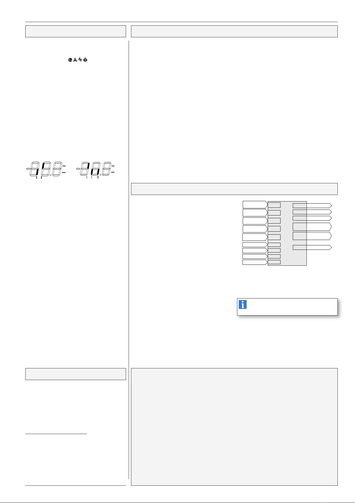
L01 ..............X.........Actual humidity value at sensor 1
.......................................................................................................
0...+100% r.H. ........... ---
(All inputs are correctable in the mode page, functions are selected in the assignement page)
L05 ..............X.........Actual humidity value at sensor 5............................................................................................. 0...+100% r.H. ............ ---
L06 ..............X.........Actual humidity value at sensor 6............................................................................................. 0...+100% r.H. ............ ---
L20 ..............X.........Current Failure ............................................................................................................................................................... ---
L36 ..............X.........Remaining min. idle time dehumidify........................................................................................ minutes
L37 ..............X.........Remaining min. idle time humidification................................................................................... minutes
L41 ..............X.........Dehumidify control (0 = off, 1 = on, oFF = switched off from the VPR)................................... 0, 1, off
L43 ..............X.........Day/Night Mode (0 = day, 1 = night)......................................................................................... 0, 1
L44 ..............X.........Operation state of the controller ............................................................................................... on, off
L50 ..............X.........Current value of the analogue output in X% of the selected range......................................... 0-100%
L60 ..............X.........States of the digital inputs DI 1 and DI 2..................................................................................
L61 ..............X.........States of the relays 1-3 .............................................................................................................
Mode Page (P)
Param. Note Range Factory Setting
P01 ..........................Assigned to compound no. (0 = not assigned) ............................... 0, 1, 2,, 3 ..................................................................0
P21 ..........................Night operation ON at (In 10 min. steps).........................................00.0 ... 23.5, oFf .....................................................oFf
P22 ..........................Night operation OFF at (In 10 min. steps).......................................00.0 ... 23.5, oFf .....................................................oFf
P31 ..........................Calibration of humidity sensor 1 ......................................................+/- 20,0 % adjustable ...............................................0,0 %
P35 ..........................Calibration of humidity sensor 5 ......................................................+/- 20,0 % adjustable ..............................................0,0 %
P36 ..........................Calibration of humidity sensor 6 ......................................................+/- 20,0 % adjustable ..............................................0,0 %
P41 ..........................Actual value display resolution ........................................................0 = 1%, 1 = 0,1% ....................................................1
P51 ..........................Analogue output delivers 0V resp. 4mA if control sensor temp.=.....0,0...100,0 % ............................................................0,0 %
P52 ..........................Analogue output delivers 10V resp. 20mA if contr. sens. temp. =....0,0...100,0 % ............................................................100,0 %
P70 ..........................Standard of summer/winter switch ..................................................0 = oFF, 1 = EU, 2 = tVn (variable) ........................1
P71 ...........................Time Zone Offset..............................................................................-720...720 min. .........................................................60 min.
P72 ...........................SummerON Month ..........................................................................(only for tVn) 1...12 ..................................................3
P73 ...........................SummerON Day...............................................................................(only for tVn) 0(Sund.)...6 .......................................0
P74 ...........................SummerON x-Day............................................................................(only for tVn) 0...5(last), 0 = off................................5
P75 ...........................SummerON Hour .............................................................................(only for tVn) 0...23..................................................2
P76 ...........................SummerOFF Month .........................................................................(only for tVn) 1...12..................................................10
P77 ...........................SummerOFF Day.............................................................................(only for tVn) 0(Sund.)...6........................................0
P78 ...........................SummerOFF x-Day..........................................................................(only for tVn) 0...5(last), 0 = off................................5
P79 ...........................SummerOFF Hour ...........................................................................(only for tVn) 0...23..................................................3
P80, P81 ..................Year, Month
P82, P83 ..................Day, Hour
P84, P85 ..................Minute, Second
P87 ..........................Software version
P89 ..........................Data transmission speed (Baudrate)...............................................12(00)...115(00)........................................................96(00)
P90 ..........................Address of the controller unit in a network ......................................0 - 78.........................................................................78
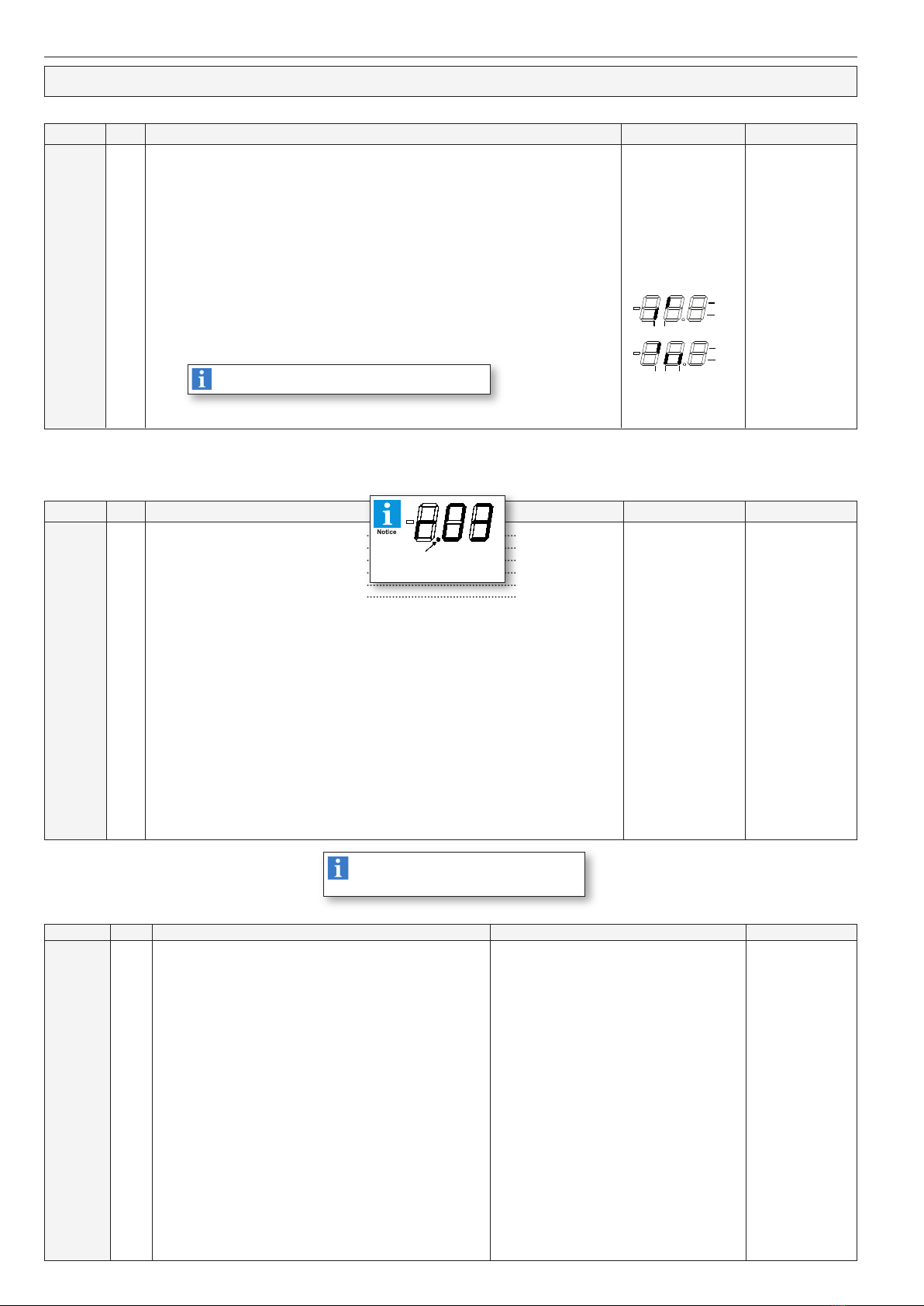
Parameters marked by "Disp" are for information only
and cannot be changed.
Due to the free assignment, not all parameters
are required.
All not required parameters will be fade out.
If this point is ON while displaying a
parameter number, the parameter is
active at present
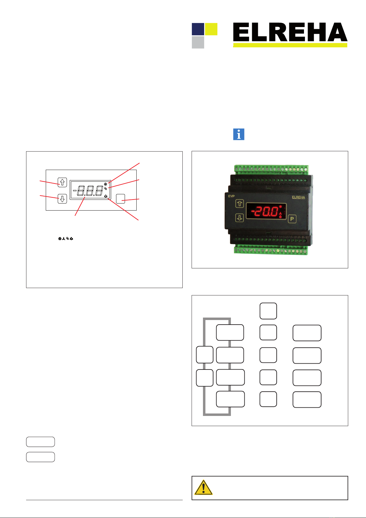
Relays
ON
OFF
mains
0V