ELREHA TAR 1170 User manual

General
ThiscontrollerisasinglecircuitON/OFF
controller for any refrigeration applica-
tions. A 2
nd
, configurable operation
mode with a cyclic defrost function
makes the TAR (TARN) 1170 suitable
for applications like refrigerated coun-
ters or similar.
Function
The controller senses the actual tem-
peraturewith atemperature probe.The
valuecanbedisplayed as°Cor°F.This
value is compared with control setpoint
and according to the difference the out-
put relay switches ON or OFF. A cycle
timer starts a defrost event by stopping
the refrigeration for a certain time. Furt-
her functions you will find in the para-
meter listing.
Operating Elements
Operating
Operatingthecontrollerisveryeasy.Af-
ter power-up, the operation mode ap-
pears on the display and after appr. 3
sec. the actual temperature.
Calling up Parameters
• Push „P“, ParameterNo. appears
•Select parameters by „ñ/ò“
• Push „P“ again,
Parameter value becomes visible
•Change Parameter value by „ñ/ò“
• Push„P“again,Newvalueisstored,
back to parameter-no.
Access Code
Only the Control setpoint can be set
unprotected. All other parameters are
protected by an access code.
The code for all controllers is "88":
• Push "P"
• Select P09 or P21 (depending on
Operating mode) by keys „ñ/ò“
• Push "P" once more
• Select CodeNo. ( 88 ) by key "ñ".
• Push "P" again
Parameter-No. appears again
Ifyou don´tpressany keyfor aboutone
minute, the access code is canceled.
Defrost
The first defrost after power-up starts
afterthe timeset byP10. IfP11is setto
'0' the defrost function is disabled.
Defrost manually ON
Hold key "ñ" for >2,5 sec while the
display shows the actual temperature.
Defrost manually OFF
Hold key "ò" for >2,5 sec while the
display shows the actual temperature.
Notice technique 5311073-00/05 F
Régulateur de T°c avec dégivrage
Temperature Controller with Defrost
Type:
TAR 1170
Modèle 2
TAR 1170
/24
TAR 1170 V
Modèle 2
TARN 1170
Modèle 2
TARN1179
TARN1170 V
Applications
Le TAR (TARN) 1170 est un thermo-
stat électronique tout ou rien avec dé-
givragecycliquenaturel.Ilpossèdeun
relais pour la commande de
l’électrovanne ou compresseur.
Fonctionnement
Lecapteurdetempératuretransmetla
mesure au processeur. La valeur
s’affiche en °C ou °F. Selon la dif-
férenceentremesureetconsigne,ain-
si que l’hystérésis, le relais commute.
L’horloge cyclique gère le dégivrage
enbloquant le relaispendant letemps
configuré. Les autres fonctions sont
décrites dans la liste des paramètres.
Utilisation
Utilisation
La programmation est simple. A la
mise en route, l’afficheur indique le
modefonctionnementdel’appareilpuis
au bout de 3 sec., la mesure apparaît.
Changer un paramètre
• Appuyer sur „P“
N° du paramètre apparaît
• Appuyer sur „ñ/ò“
Choisir le paramètre
• Réappuyer sur „P“
La valeur apparaît
• Appuyer sur „ñ/ò“
Modifier la valeur
• Réappuyer sur „P“
La nouvelle valeur est
validée, retour au n° du
paramètre.
Code de déverrouillage
Seul la consigne se modofie sans dé-
verrouiller l’appareil. Pour changer les
autresparamètres,ilfautentrerlecode
--88-- au dernier paramètre :
• Appuyer sur „P“
•(selon le mode fonctionnement),
Choisir P21 ou P09 avec „ñ/ò“
• Réappuyer sur „P“,
• Régler la valeur ( 88 ) avec „ñ“
• Réappuyer sur „P“
Lenuméroduparamètreréapparaît
et le régulateur est déverrouillé.
Si aucune touche n’est appuyée pen-
dant 1 minute, l’appareil se vérrouille
automatiquement.
Dégivrage
A la mise en route, le 1
er
dégivrage
débuteaprèsletempsP10. SiP11est
réglé sur „0“, la fonction dégivrage est
arrêtée.
Dégivrage manuel On
La mesure est affichée : appuyer sur
"ñ" plus de 2,5 secondes.
Dégivrage manuel Off
La mesure est affichée : appuyer sur
"ñ" plus de 2,5 secondes.
Vor Inbetriebnahme diese Bedienungsanleitung sorgfältig lesen! Entstehen durch Nichtbeach-
tung Schäden, erlöschen die Garantieansprüche. Diese Dokumentation würde mit größter Sorg-
falt erstellt. Dennoch können wir für die vollständige Richtigkeit keine Garantie übernehmen.
Please read these instructions carefully before applying power. Your attention is drawn to the
fact that the warranty is subject to the application of power sources that are within the limits
specified in this manual. Repairs or modifications made by anyone other than ELREHA will also
void the product warranty. This documentation was compiled with utmost care, however, we
cannot guarantee for its correctnesss in every respect.
ELEKTRONISCHE REGELUNGEN GMBH
ELREHA Gmbh
D-68766 Hockenheim,
Schwetzinger Str. 103
Configuration
L’appareil possède 2 modes de
fonctionnement.
Mode 1: Pour les applications
générales, 9 paramètres.
Mode 2: Pourlespostesdefro-
idavecdégivragecycliquenaturel,21
paramètres.
D’usine, l’appareil est réglé sur le
mode de fonctionnement 1.
Choisir le mode de fonctionnement:
• Débrancher l’appareil
• Maintenir „P“ appuyé
• Mettre l’appareil sous tension
• Maintenir „P“ jusqu’à ce que „17_“
apparaisse
• Avec la touche „ñ“(>1sec),
régler sur „171“ pour le mode 2.
• Avec la touche „ò“(>1sec),
régler sur „170“ pour le mode 1.
Ensuite,l’afficheurindique„def“puis„-
- -“ et les valeurs d’usine sont char-
gées, la configuration est terminée.
Si vous changer le mode de
fonctionnement l’appareil re-
prend ses valeurs d’usine.
Configuration
The controller can work in two opera-
ting modes.
Mode 1: Forstandardapplicati-
ons, 9 parameters
available.
Mode 2: For cold storages, 21
parameters available.
Without configuration (default value)
the controller works in mode 1.
How to change an operation mode:
• Switch controller off
• Push and hold „P“
• Switch controller on
• Hold „P“ until „17_“ appears
• Select „171“ for Mode 2 by key „ñ“
(>1sec.) or
• Select „170“ for Mode 1 by key „ò“
(>1sec.)
After that the display shows „def“,
„---“andtheselectedoperatingmode.
With this, the configuration is finis-
hed. While changig the operating
mode all values will be reset
to default.
ELREH A
Programmingmode
Touche de
programmation
Relayposition(blinking=MinimumStop-Timeruns)
Etatdurelais (clignote=l'anti-courtcycle s'écoule)
Defrost, dégivrage
LED 3: 1179
1179 only: Decimalpoint
ne que 1179 : Point
Decreasevalues
Touche pourdiminuer
Increasevalues
Touche pour
augmenter
TAR
1
ELREHA
P
23

Parameter Explanation
Mode 1 Mode 2
P01 P01 Actual sensor temperature in °C /°F (displ.only)
*P02 *P02 Control setpoint, can be changed at any time
within the limits set by P04 and P05
P03 P03 Switching differential (hysteresis) of control setpoint
def. 2K, range 2...10K / 4...18F (from 0,2 in an 1179)
P04 P04 Highest adjustable Setpoint (default +50°C)
range -50...+100°C (-58..212°F)
P05 P05 Lowest adjustable Setpoint (default -50°C),
range -50°C/-58°F...P04
P06 P06 Relay action
1= Refrigeration
(Default)
2= Freezing
3 = Heating
!! Defrost function
de-activated
P07 P07 Display Mode / Sensor Type
0= TF201/°C, 1= TF201/°F
2= TF202/°C, 3= TF202/°F (Default = 0)
P08 P08 Sensor Correction
(range ±10K or ±18F )
P09 Defrost Start by
1=
cyclic air defrost
, this means a defrost event will
be started after the interval timer P10 has been run
down. This timer always starts with power-up of the unit.
2=
Air defrost depending on machine runtime
All ON-times of the cooling relay will be added and
stored. A defrost starts, if the added ON-times exceed
the value set by P10. Then the timer will be reset.
-- P10 Defrost Cycle / Machine Runtime
range 1...99 hours (default 4 h.)
-- P11 Defrost Duration
0...99 min., 0=no defrost (default 15 min.)
After that refrigeration will be restartet.
-- P16 Minimum Idle Time of Refrigeration
0...99 min. (default 0 min.)
-- P17 Info: Remaining time till next defrost
-- P18 Info: Remaining time actual defrost event
-- P20 Info: Remaining time refrigeration stop
P09 *P21 Access Code, Code is --- 88 ---
The marked " *" parameters can be set without access code.
Default values are set by the manufacturer.
warm
sta
g
e on
sta
g
e off
setpoint
hysteresis
cold
warm
sta
g
e on
sta
g
e off
setpoint
hysteresis
cold
warm
sta
g
e on
sta
g
e off
setpoint
hysteresis
cold
Paramètres et description
Mode1 Mode2
P01 P01 Mesure de la sonde en °C /°F (Affichage seulement)
*P02 *P02 Consigne de régulation, se modifie sans code dans
la plage de régulation programmée en P04/P05
P03 P03 Hystérésis de régulation
Usine 2K, Plage 2...10K ou 4...18F (0,2 en 1179)
P04 P04 Seuil haut consigne (Usine +50°C)
Plage -50..+100°C (-58..212°F)
P05 P05 Seuil bas consigne (Usine -50°C)
Bereich -50°C/-58°F...P04
P06 P06 Comportement de commutation du relais
1= Réfrigération
(Usine)
2= Congélation
3 = Chauffage
!! Dégivrage hors
fonction
P07 P07 Mode d’affichage / Type de sonde
0= TF201/°C, 1= TF201/°F
2= TF202/°C, 3= TF202/°F (Usine = 0)
P08 P08 Correction d’affichage
(Plage ±10K ou ±18F )
-- P09 Mode de dégivrage
1=
Dégivrage cyclique naturel
, signifie que le
dégivrage s’active toutes les périodes P10.
Le temps débute à la mise sous tension.
2=
Dégivrage cycl. naturel selon durée de réfrigération.
Tous les temps de marche de réfrigération sont additionnées.
Le dégivrage s’active lorsque la duré totale atteint
le temps P10. Après dégivrage, le compteur se remet à zéro.
-- P10 Dégivrage : Période / Durée réfrigération
Plage 1...99 heures (Usine 4 h.)
-- P11 Durée de dégivrage
0...99 min., 0=pas de dégivrage (Usine 15 min)
Après, la réfrigération se remet en route
-- P16 Anti-court cycle réfrigération
0...99 min. (Usine 0 min)
-- P17 Affichage: durée restante avant prochain dégivrage
-- P18 Affichage: durée restante avant fin dég. actuel
-- P20 Affichage: durée anti-court cycle actuel
*P09 *P21 Code de déverrouillage, le code est --- 88 ---
Les paramètres précédés du signe " * " peuvent être modifiés sans
déverrouiller l’appareil. Usine sont les valeurs réglées en usine.
Chaud
Eta
g
e On
Eta
g
e Off
Froid
Hystérésis
Consigne
Chaud
Eta
g
e Off
Froid
Hystérésis
Consigne
Eta
g
e On
Chaud
Eta
g
e On
Eta
g
e Off
Froid
Hystérésis
Consigne
Dé
g
ivra
g
e arrêté
Dé
g
ivra
g
e activé
Off
Durée
dé
g
iv.
On
Période P10
Defrost Off
Defrost On
Off
Defrost
duration
On
Defrost cycle

Installation
Precautions !
lElectrical installation and putting into service must be done from
authorized personnel.
lPlease note the local safety instructions !
lPlease note the maximum ratings !
If you have to lengthen the sensor cables, use a shielded type with one end of the
shield connected to ground. This minimizes the effect of irregular switching events
caused by electromagnetic interference.
Thesensorleadsmaybeuptohundredmeterslong.Anywiresizefrom0.5sqmmup
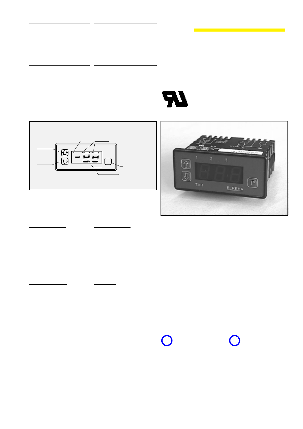
can be used. After the power has been switched on, the controller will display the
actual sensor temperature.
After programming the access code, you can set the basic adjustments according to
the application.
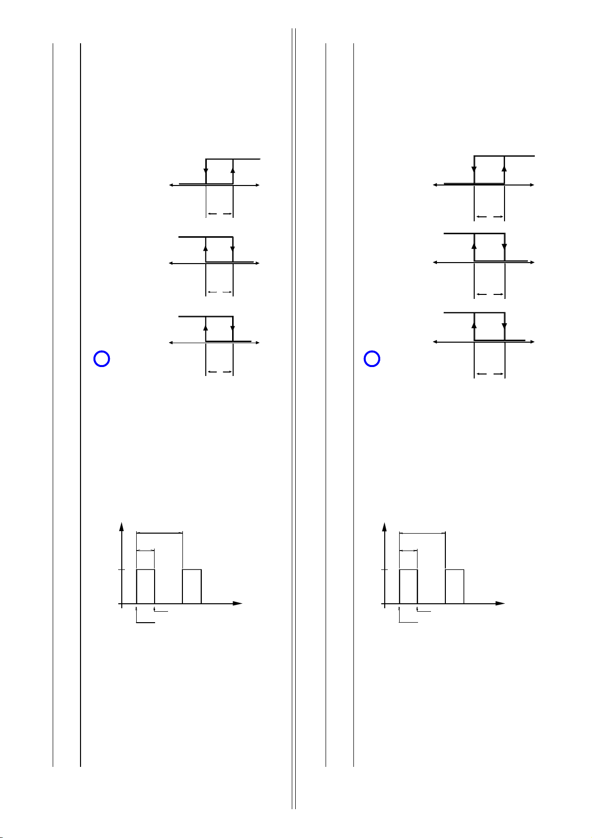
lOperating Mode (Configuration, see page 1)
lSet relay action with P06
lSet display mode / sensor type with P07.
lIf the displayed value of sensor temperature shows any offset from the actual
value you can use parameter "P08" to correct it.
lSet setpoint range with P04/P05 if necessary.
Now the desired control setpoints can be entered. Informations about running timers
you will find at P17-P20.
Failure Display
Display flashing -> value -60 = sensor short
Display flashing -> value 110 = sensor broken
Ifthecontrollerdetectsabrokenorshortedsensor, (ortemp.isnotwithin-60/+110°C)
cooling will be switched off after 1 minute.
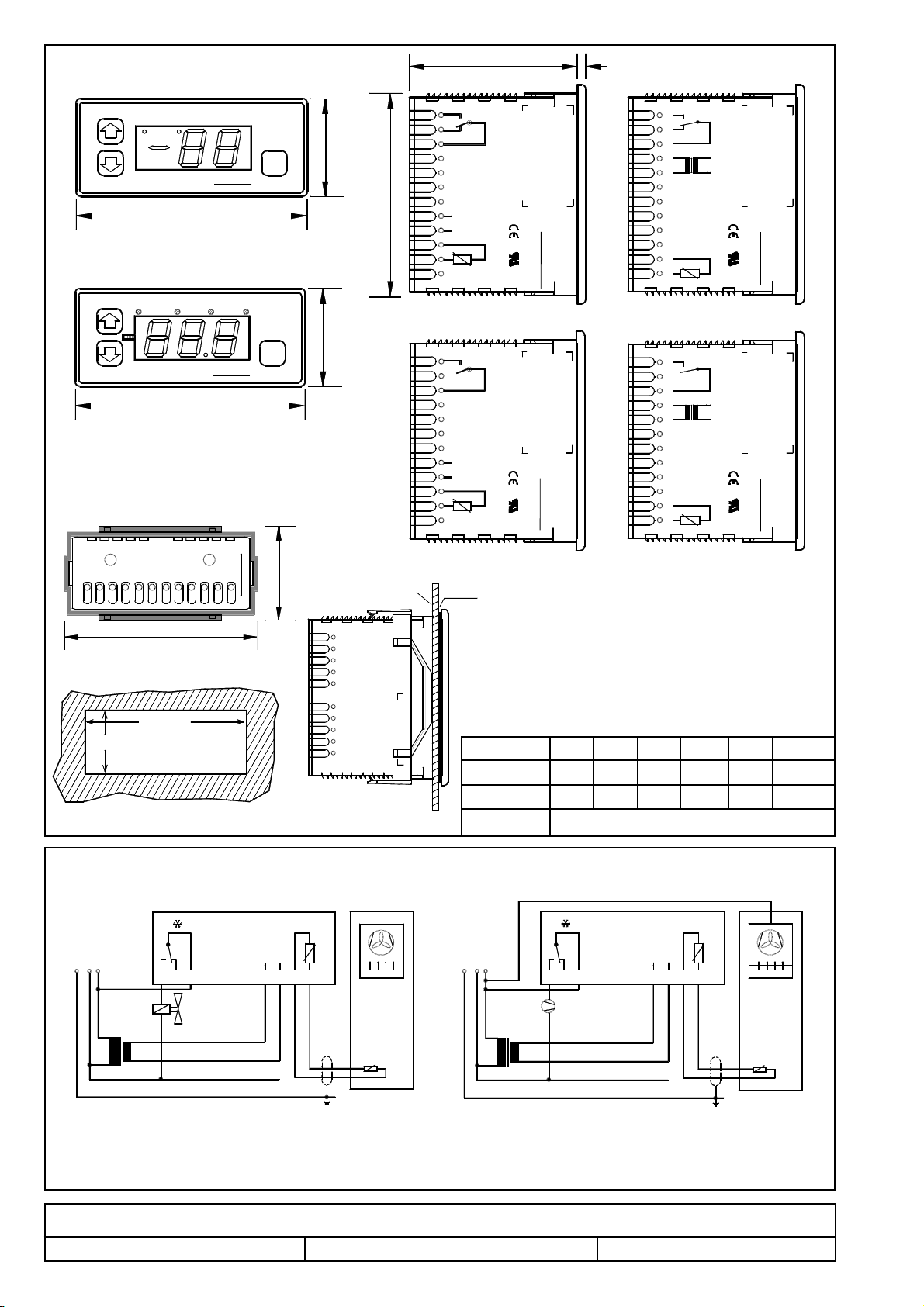
Technical Data
Supply Voltage ....... TAR 1170 (V) .... 12V AC/DC (12-18VDC)
TAR 1170/24 ..... 24V AC/DC
TARN 1170 ....... 230VAC / 50-60 Hz
TARN 1179 ....... 230VAC / 50-60 Hz
TARN 21170 ..... 110VAC / 60 Hz
Power consumption ............................ max. 2,0 VA
Relay Rating ........... TAR 1170 .......... 8A cos phi=1, 3A ind. / 250V~
TAR 1170/24 ..... 8A cos phi=1, 3A ind. / 250V~
TARN 1170 ........ 8A cos phi=1, 3A ind. / 250V~
TARN 1179 ........ 8A cos phi=1, 3A ind. / 250V~
TAR 1170V ........ 10A res., 80A / 20 msec / 250V~
TARN 1170V ..... 10A res., 80A / 20 msec / 250V~
TARN 21170V ... 10A res., 80A / 20 msec / 250V~
Temp. Range .......... working.............. -10...+55°C (14...131°F)
storage .............. -20...+60°C (-4...140°F)
Display Range .................................... -60...+110°C (-76...230°F)
(1179 : -50...99,9°C)
Control Range .................................... -50...100°C (1179 : -50...99,9°C)
Resolution .......................................... 1K (1°F), TARN 1179 : 0,1 K
Accuracy............................................. ±1K
Display ...............................................LED red 1/2"
Relay position indicator ...................... 1,2 mm red
Screw terminals .................................. 2,5mm²
Protection class .................................. IP 54 from front
EG-Konformitätserklärung
EG-Statement of Conformity
Für das beschriebene Erzeugnis wird hiermit bestätigt, daß bei bestimmungsgemäßem Gebrauch die Anforderungen eingehalten werden, die in der
Richtlinie des Rates zur Angleichung der Rechtsvorschriften der Mitgliedsstaaten über die elektromagnetische Verträglichkeit (89/336/EWG) festgelegt
sind. Diese Erklärung gilt für alle Exemplare, auf die sich die vorliegende Bedienungsanleitung (welche selbst Bestandteil dieser Erklärung ist) bezieht.
We state the following: When operated in accordance with the technical manual, the criteria have been met that are outlined in the guidelines of the council for
alignment of statutory orders of the member states on electro-magnetic consistency. ( 89/336/EWG ) This declaration is valid for those products covered by the
technical manual which itself is part of the declaration.
Zur Beurteilung des Erzeugnisses hinsichtlich elektromagnetischer Verträglichkeit wurden folgende Normen herangezogen:
Following standards were consulted for the confirmity testing with regard to electromagnetic consistency :
IEC 1000-4-1, IEC 1000-4-2, IEC 1000-4-3*, IEC 1000-4-4, IEC 1000-4-5, EN 55011 B, EN 50081, Teil 1 und 2;
EN 50082, Teil 1 und 2, EN 61000-4-6, EN 61000-4-11
Diese Erklärung wird verantwortlich vom Hersteller/Importeur
This statement is made from the manufacturer / importer by:
ELREHA Elektronische Regelungen GmbH Klaus Birkner, QL / Leiter EMV-Labor
68766 Hockenheim
Hockenheim 12.10.2000 ......................................................
(Ort) (Datum) (Unterschrift)
*DieEinhaltungdesGrenzwertesnachIEC1000-4-3wirdausdenvorgenommenMessungennachIEC1000-4-2undIEC1000-4-4abgeleitet.Die Korrelation auf IEC
1000-4-3 basiert auf entsprechenden Versuchsmessungen, deren Ergebnisse beim Hersteller hinterlegt sind.
*The conformity with IEC 1000-4-3 is derived from the IEC 1000-4-2 and IEC 1000-4-4 test results. The correlation with IEC 1000-4-3 is based on test results which
are located on site at the manufacturer.
Installation / Mise en route
Attention !
lLes raccordements électriques doivent s’effectuer par un
spécialiste
lVérifier les consignes générales de sécurité du pays ou
l’appareil est installé.
lVérifier bien le schéma de raccordements électriques.
Silecâble desondeest rallongé,ilest préférabled’utiliserun câbleblindé,de section
minimale0,5mm
2
.Nepasplacer lecâbleenparallèleavec descâbleshautetension.
Le blindage doit être raccorder d’un seul côté à la terre.
A la mise sous tension, l’appareil indique la mesure actuelle.
Une fois avoir entré le code de déverrouillage, il reste à effectuer les réglages:
lRégler le mode de fonctionnement (Configuration, voir page 1)
lProgrammer le choix de comportement du relais en P06
lMode d’affichage et type de sonde en P07.
lSi la mesure est faussée à cause du rallongement de la sonde, effectuer
la correction en "P08".
lPlage de régulation (selon besoin) avec P04/P05
Ensuite, vous pouvez régler les consignes. P17 à P20 informent sur les temps de
fonctionnement...
Affichage des défauts
L’afficheur clignote et indique -60 = Court-circuit de la sonde
L’afficheur clignote et indique 110 = Coupure de sonde
En cas de court-circuit ou coupure de sonde, le relais tombe au bout d’un minute.
Données techniques
Alimentation ........... TAR 1170 (V) .... 12V AC/DC (12-18VDC)
TAR 1170/24 ..... 24V AC/DC
TARN 1170 ....... 230VAC / 50-60 Hz
TARN 1179 ....... 230VAC / 50-60 Hz
Consommation ................................... max. 2,0 VA
Puissance relais ..... TAR 1170 .......... 8A cos phi=1, 3A inductif / 250V~
TAR 1170/24 ..... 8A cos phi=1, 3A inductif / 250V~
TARN 1170 ....... 8A cos phi=1, 3A inductif / 250V~
TARN 1179 ....... 8A cos phi=1, 3A inductif / 250V~
TAR 1170V ....... 10A nominal, 80A / 20 msec
TARN 1170V ..... 10A nominal, 80A / 20 msec
T°c fonctionnement ............................ -10...+55°C
T°c stockage ...................................... -20...+60°C
Plage d’afficheur................................. -60...+110°C (1179 : -50...99,9°C)
Plage de régulation............................. -50...+100°C (1179 : -50...99,9°C)
Résolution .......................................... 1 K, TARN 1179 : 0,1K
Précision ............................................ ± 1K
Afficheur ............................................. 7 segments rouges, 13mm
Affichage état ..................................... 1,2 mm, rouge
Connexions ........................................ bornier 2,5mm²
Protection ........................................... IP 54 en façade

erstellt: 20.2.2003, tkd/jr geprüft: 20.2.2003, mv/tn freigegeben: 20.2.2003, mv/sha
Diese Anleitung haben wir mit größter Sorgfalt erstellt, Fehler können wir aber nie ganz ausschließen. Bei Problemen oder Fragen wenden Sie sich bitte an unsere
Kundenbetreuung. Unsere Produkte sind ständiger Pflege unterworfen, Konstruktions- und Softwareänderungen sind also möglich und vorbehalten.
Exemples d’application TAR 1170
Application Examples with TAR 1170
123456
Re
g
elfühler
12
AC/DC
8791110
12 V
123456
Re
g
elfühler
12
AC/DC
87 9 1110
12 V
Thermostat On/Off
Simple ON/OFF control
Thermostat On/Off avec dégivrage cyclique naturel
Simple cold storage with airflow defrost
Dimensions
Tableau de correspondance °C / Ohms
Température -20°C -10°C 0°C +10°C +20°C +25°C
TF 201 1366 1493 1628 1771 1922 2000
TF 202 677 740 807 877 951 990
Resistance (Ohms)
Rückansicht mit Befesti
g
un
g
srahmen
75 (2.95)
rear view with mountin
g
frame
81234567
37 (1.46)
9 101112
76 (3.0)
TAR
1 2
P
35 (1.38)
ELREHA
3
10
9
6
7
8
5
4
3
2
1
Tür/Panel Dichtun
g
g
asket
28 (1.1)
70 (2.76)
Ausschnitt
ELREHA
3
TAR 1170
70 (2.76)
12 V
AC/DC
Temperaturregler
Temperature Controller
10
11
12
9
7
8
5
6
4
2
1
56 (2.2) 3 (.12)
TAR 1170 - 1170/24 TARN 1170 / 1179
54321
TARN 1170
Temperaturregler
Temperature Controller
ELREHA
230VAC
K1
11 12
F1
11 1254321
TARN 1170 VST
TARN 1170 V
Temperaturregler
Temperature Controller
ELREHA
F1230VAC
K1
TAR 1170 V TARN 1170 V
5
12
10
11
7
9
8
6
12 V
AC/DC
3
4
2
1
ELREHA
Temperaturregler
Temperature Controller
TAR 1170 V
TARN 1179
P
TAR ELREHA
76 (3.0)
1 432
35 (1.38)
This manual suits for next models
5
Table of contents
Other ELREHA Controllers manuals

ELREHA
ELREHA TAR 1380 User manual

ELREHA
ELREHA TAR 1370-2 User manual

ELREHA
ELREHA EVP 3260 User manual

ELREHA
ELREHA MSR eco 3140 User manual

ELREHA
ELREHA TAR 1260 User manual

ELREHA
ELREHA EVP 3150-1 User manual

ELREHA
ELREHA TKP 3130/1 User manual

ELREHA
ELREHA MSR 100 Series User manual

ELREHA
ELREHA TAR 1370 User manual

ELREHA
ELREHA TARN 1600 User manual
Popular Controllers manuals by other brands

Carel
Carel IR32 Series user manual

Furious FPV
Furious FPV F-35 LIGHTNING user manual

HKC
HKC HL Series Installation & operation manual

Advanced Energy
Advanced Energy Thyro-PX user manual

Lightronics
Lightronics TL - 2448 owner's manual

NOVAK
NOVAK HAVOC 3S - GEARING AND ADJUSTABLE PARAMETERS 4-2010... manual