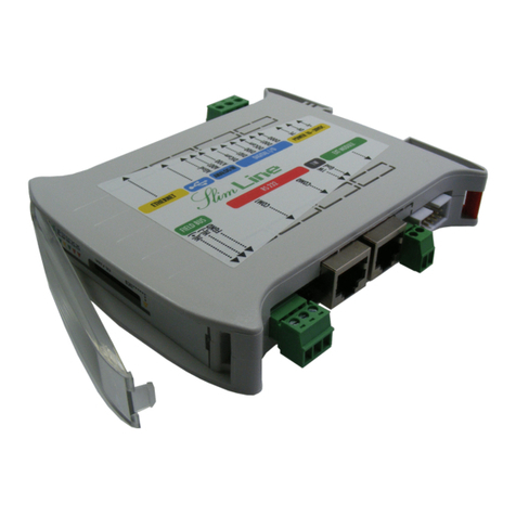
Elsist SlimLine MPS055 00 Series User manual

HDMI
USB
A/V
7 Identificazione prodotto
Product identification
LB L052E0 00
Code:
MPS055**00
Serial Nr:
00348
MPS055**00
Livello modulo
Module relea e
Lite ver ion = 0
RS485 ver ion = 1
CAN ver ion = 2
Bus 1-Wire (P11) Bus I2C (P7)
Pin Si nal Pin Si nal Pin Si nal
1 1-Wire 1 +5Vdc 6 GND
2 GND 2 +5Vdc 7 SCL
3 +5V (Aux) 8 GND
4 +5V (Aux) 9 SDA
5 RDYO-N 10 GND
9
Field Bus (P2)
CAN RS485
Pin Si nal Pin Si nal
1 CAN H 1 D+
2 CAN L 2 D-
3 Field GND 3 Field GND
LK1 ON= Line Terminated (120Ω)
4 Bus di campo
Field bus
Via G. Brodolini, 15 (Z.I.) 15033 CASALE M.TO (AL) ITALY
Phone +39-0142-451987 Fax +39-0142-451988
Internet: http://www.el i t.it email: el i t@el i t.it
SlimLine
SlimLine
Raspberry PI
Raspberry PI
CPU Module
CPU Module
Hardware
Hardware
Manual
Manual
MNL195A100
10 Colle amento moduli di espansione
Extension modules connection
5 Dimensioni
Dimensions
119mm 22,5mm
101mm
Ethernet
Pin Si nal Pin Si nal
1 ETH1 5 N.C.
2 ETH2 6 ETH6
3 ETH3 7 N.C.
4 N.C. 8 N.C.
LED Yellow Speed 1Gb
LED Green Speed 10/100Mb
1 Porta Ethernet
Ethernet port
USB Host
Pin Si nal
1 Vcc (5V 100mA/port max.)
2 D-
3 D+
4 ID
5 GND
2 USB Host
Host USB
Bus 1-Wire e Bus espansione
1-Wire and Extension bus
I/O Module
I/O Module
CPU Module
P11
119
10 2
P7
13
LK1 P1
18
CPU Status
LED Function
PWR
(LD1)
(Green)
ON=Power OK
OFF= Power
fault
RUN
(LD4)
(Yellow)
Regular Blink =
Sy tem OK
RDY
(LD3)
(Green)
ON=Sy tem
Ready
OFF=Sy tem Not
Ready
8
8 Alimentazione/Stato CPU
Power supply/CPU Status
Tenere corto e di tante
da fonti di di turbo
Keep it hort and away
from noi e ource
Fu e 1AT
Vmax=30Vdc
!
1
P8
1
LD1 LD3 LD4
Me a a terra pulita
Clean GND
microSD
Solo per alimentazione aux. 5Vdc
Auxiliary power upply 5Vdc only

Technical Specifications
Device Code MPS055*000 MPS055*100 MPS054*200
Power Supply 10-30Vdc 3W (1) 10-30Vdc 3,3W (1)
Power to exp. bu 5Vdc 2A max.
Proce or Broadcom BCM2837B0, Cortex-A53 64-bit SoC @ 1.4GHz max
Memory 1GB LPDDR2 SDRAM
Ma memory On micro-SD card lot (MicroSD-CARD 8GB HC provided)
File y tem Ra pbian Standard
FTP erver Ye
Real Time Clock
Ye , off- y tem operation with lithium battery (5 year min.)
SNTP (Simple Network Time Protocol) upported
USB I/F 4 USB-A port (ho t mode) 2.0 USB compatible (5V 100mA/port max.)
1-Wire I/F 1
Ethernet I/F RJ45 10/100/1000ba e-T (x) Auto-MDIX (300Mbp max upported)
WiFi I/F 2.4GHz and 5GHz compatible 802.11b/g/n/ac
Bluetooth I/F Bluetooth 4.2, Bluetooth Low Energy (BLE)
HDMI I/F 1 Full ize
Compo ite video I/F 1 tereo out + compo ite video
Field bu none In ulated Fail Safe High impedance
RS485
In ulated CAN Bu 2.0B compatible,
ISO11898-1
Expan ion bu I2C™
Expan ion module 8 max. (to be verified according to the connected module)
Statu indicator Power, RUN, READY
U er configurable web
page Ye (re pon ive)
Environment
Operating temperature: from -0 to +50°C
Storage temperature: from -40° to +80°C
Relative Humidity: Max. 90%
Dimen ion and weight
Dimen ion : 22.5 mm L x 101 mm W x 120 mm H
Weight: 160g
Approval CE, RoHS
Note (1) Wor t ca e
Connessioni
La CPU SlimLine Ra pberry PI è dotata di mor etti e traibili
per la conne ione dell’alimentazione e Bu di campo, connettore
IDC per il collegamento dei moduli di e pan ione, connettore RJ45
per il collegamento della porta Ethernet e di connettori USB-A per
la conne ione delle porte USB Ho t.
Alimentazione (Fi . 8)
Il modulo deve e ere alimentato con una ten ione continua
nel range 10-30V. La conne ione della alimentazione deve e ere
effettuata in accordo alla Fig. 8.
La pre enza della ten ione di alimentazione è egnalata dal
LED verde “PWR”.
ATTENZIONE! Il superamento del valore massimo di
tensione indicato può provocare il danne iamento
irreversibile dell’apparato.
Colle amento di terra (Fi . 8)
Il di po itivo deve e ere collegato direttamente a terra
mediante l'appo ito mor etto del connettore di alimentazione (Fig.
8).
Il collegamento deve e ere e eguito mediante una cordina
avente ezione di almeno 1.5mm2, ad una barra equipotenziale di
rame di adeguata ezione.
Al fine di garantire una buona rejezione ai di turbi, è
nece ario che que to collegamento ia mantenuto il più corto
possibile e non ven a fatto passare con altri cavi.
Bus di espansione e 1-Wire (Fi . 9)
Il bu di comunicazione con i moduli di e pan ione frutta
l’interfaccia I2CTM ed è di ponibile u connettore P7. I moduli di
e pan ione devono e ere collegati in ca cata tramite gli appo iti
cavetti CBL074*000 e/o CBL045*000 (da ordinare eparatamente).
In Fig. 10 è chematizzato il collegamento dei moduli di
e pan ione.
Al modulo CPU po ono e ere collegati fino a 8 moduli di
e pan ione (previa verifica a orbimenti ma imi).
ATTENZIONE! Prima di colle are al modulo CPU i
moduli di espansione, accertarsi che questo non sia
alimentato. In caso contrario i dispositivi potrebbero
essere irrimediabilmente danne iati.
Il di po itivo è dotato di bu 1-WireTM (P11), attraver o il quale
è po ibile l'acqui izione di di po itivi i-ButtonTM, quali TAG di
identificazione per onale, en ori di temperatura e molto altro.
Bus di campo (Fi . 4)
Il modulo può e ere dotato di bu di campo RS485 o CAN
Bu (vedi identificazione prodotto Fig. 7), i olato galvanicamente
dal i tema. Per il collegamento del bu attener i alla figura a lato.
Attraver o il jumper LK1 può e ere in erita la re i tenza di
terminazione 120Ohm o meno.
Porta Ethernet (Fi . 1)
Il modulo può e ere dotato di una porta ethernet di ponibile
ul connettore RJ45; le conne ioni, evidenziate in Fig. 1, ono
compatibili con lo tandard ethernet IEEE 802.3 10/100/1000ba e-T
(x). Per l’in erimento in una rete ethernet devono e ere utilizzati
cavi UTP Cat. 5 RJ45 ed uno witch, mentre, per un collegamento
punto-punto, è ufficiente utilizzare un cavo patch RJ45 enza
utilizzo di altri di po itivi. Il di po itivo è dotato di Auto-MDIX, quindi
non è nece ario di porre di cavo cro per il collegamento diretto
a PC.
Sul connettore ethernet ono di ponibili due LED di
egnalazione dello tato della conne ione:
Il LED Verde egnala, quando acce o, che la rete ta
funzionando a 100Mb/ .
Il LED Giallo egnala, quando acce o, che la rete ta
funzionando a 1Gb/ .
Il modulo viene fornito con DHCP abilitato.
Porte USB Host (Fi . 2)
Il modulo è dotato di 4 porte USB-A Host. Po ono e ere
collegati a que te porte di po itivi quali pen drive, tampanti,
modem ecc.. Il modulo è in grado di fornire l'alimentazione al
di po itivo e terno (5V 100mA max. per ogni porta).
Slot SD Card (Fi . 8)
Il modulo è dotato di uno lot micro-SD Card. La card può
e ere utilizzata ia per funzioni di archiviazione del programma
utente, che per funzioni di toricizzazione dati durante il
funzionamento.
Se nalazioni stato (Fi . 6)
Il modulo è dotato di LED per la egnalazione dello tato di
funzionamento, in particolare è egnalato lo tato di:
·PWR (LED Verde)
Indica la pre enza dell’alimentazione
·RUN (LED Giallo)
Lampeggiante regolare indica che il i tema è in funzione,
·RDY (LED Verde)
Acce o indica che il i tema è pronto e ge ti ce i moduli I/
O. La mancanza di RDY re etta lo tato delle u cite dei
moduli di e pan ione eventualmente conne i al i tema.
I2CTM è un marchio regi trato di NXP Semiconductor
1-Wire® è un marchio regi trato di Maxim/ Dalla Semiconductor
Connections
The SlimLine Cortex M7 (LogicLab) CPU module i provided of
extractable TB to connect Power and Field bu , IDC connector to
connect the exten ion module , RJ45 connector to connect
Ethernet port, and 4 USB-A connector USB ho t.
Power supply (Fi . 3)
The module can be powered with a DC ource within the range
10-30Vdc. The power connection mu t be done according to the
Fig. 8.
The power i ignalized by the green LED “PWR”.
WARNING! Values reater than the maximum allowed
may dama e the device seriously.
Ground connection (Fi . 8)
The device mu t be connected directly to Ground u ing the
terminal block on the power upply connector (Fig. 8).
The connection mu t be performed through a wire with ection
at least of 1.5mm2, to a copper equipotential bar of adequate
ection.
To guarantee a good noi e rejection, keep thi connection as
short as possible and take care to place it far away to the other
cables.
Extension bus and 1-wire bus (Fi . 9)
The communication bu with the exten ion module u e the
Fa t I2C™ interface and it’ available on the IDC10 connector (P7).
The exten ion module mu t be ca cade connected through the
pecial cable CBL074*000 and/or CBL045*000 (to be ordered
eparately).
The Fig. 9 in an example of exten ion module connection.
Up to 8 exten ion module may be connected to the CPU.
(after checking the maximum current needed)
WARNING! Before to connect the extension modules
to the system, be sure that it’s powered off. Missin
this rule may produce failures in the modules.
The device i equipped with a 1-WireTM bu (P11), through it
you can acquire i-ButtonTM device , uch a TAG for per onal
identification, temperature en or and other device .
Field bus (Fi . 4)
The module may be provided of a RS485 or CAN field bu ( ee
product identification Fig. 7), in both ca e the bu i galvanically
in ulated from the y tem. To connect the field bu plea e ee
Figure on ide.
Through the LK1 jumper may be connected or not the 120
Ohm termination re i tor.
Ethernet port (Fi . 1)
The module may be provided of an RJ45 connector; the
connection, hown in Fig. 1, are compatible with the tandard
Ethernet IEEE 802.3 10/100/100-Ba e T.
To connect the device in an Ethernet network mu t be u ed
UTP Cat. 5 cable RJ45, connected to an HUB or a witch, while to
made a point to point connection it’ enough to u e an RJ45 patch
cable without HUB . The device i Auto-MDIX, o no cro cable i
needed to connect it to a PC directly.
On ethernet connector are available two LED for connection tatu
ignaling:
The green LED ignal , when on, that the network i running at
10/100Mb/ peed.
The yellow LED ignal , when on, that the network i running at
1Gb/ peed.
The module i factory with DHCP enabled.
USB Host port (Fi . 2)
The module i equipped with 4-port USB-A able to be u ed a
host mode. Can be be connected to thi port device uch a pen
drive , printer , modem etc.. The module i capable of providing
power to the external device (5V 100mA max.).
Slot SD Card (Fi . 8)
The module may be provided of a lot mini-SD Card. The card
may be u ed for archive function or for data hi tory function
during normal running.
Status si nalin (Fi . 6)
The device i provided of ome LED to ignal it tatu ,
particularly i ignaled:
·PWR (Green LED)
Indicate that device i powered
·RUN (Yellow LED)
Regularly blinking indicate that the y tem i running,
·RDY (Green LED)
When light indicate that the y tem i ready and it
manage the I/O module according to the u er program.
When it' off it re et the output tatu on exten ion
module eventually connected to the y tem.
I2CTM i a trade mark of NXP Semiconductor
1-Wire® protocol i a regi tered trade mark of Maxim/ Dalla Semiconductor
Colle amento Half-Duplex (solo RS485)
•La di tanza ma ima tra il primo e l’ultimo dei
di po itivi non deve superare i 1200 mt (RS485)
•La re i tenza di terminazione deve e ere empre
in erita ul primo e ull’ultimo dei di po itivi.
•Il cavo deve essere schermato e twistato.
Half-Duplex connection (RS485 only)
•The maximum di tance between the fir t and the la t
device does not exceed 4000 feet (RS485).
•The termination re i tor mu t be alway connected on
the fir t and on the la t device.
•The cable must be shielded and twisted paired.
Note tecniche per connessione CAN
Le pecifiche del Bu CAN ono regolate dalla norma ISO
11898. La velocità max di tra mi ione è pari ad 1Mbit/ riferita ad
un cavo di lunghezza max. 40mt. Nella tabella otto ono riportate
le velocità max in funzione della lunghezza del cavo.
Technical notes for CAN connection
The technical pecification for CAN bu are given by the ISO
11898 Standard. The maximum bu peed i 1Mbit/ for a cable
length of 130ft. In the table below are li ted the allowed peed
function of cable length.
Massima velocità in funzione della lun hezza bus (CAN)
Max speed function of bus len th (CAN)
Lun hezza del bus
Bus Len th
Velocità trasmissione
Transmission speed
Lun hezza del bus
Bus Len th
Velocità trasmissione
Transmission speed
100 meter (330 ft) 500 kbit/ 500 meter (1600 ft) 125 kbit/
200 meter (650 ft) 250 kbit/ 6 kilometer (20000 ft) 10 kbit/
Schema di conne ione
Drawing connection
Colle amento Bus di campo
Field bus connection
!
!
!
!
13
LK1 P1
13
LK1 P1
13
LK1 P1
Other Elsist Control Unit manuals
Popular Control Unit manuals by other brands
Mitsubishi
Mitsubishi MELSECNET/10 A1SJ72QLP25 user manual

RefPlus
RefPlus Guardian+ RC-S Programming manual
Acromag
Acromag AcroPack AP441 user manual

GEM
GEM 532 Installation, operating and maintenance instructions

Watts
Watts iDROSET CSD Series installation instructions

Manner
Manner MES technical information
