Elsist SlimLine PCB124 00 Series User manual

1
Via G. Brodolini, 15 (Z.I.) 15033 CASALE M.TO (AL) ITALY
P one +39-0142-451987 Fax +39-0142-451988
Internet: ttp://www.elsist.it email: [email protected]
SlimLine
SlimLine
Static I/O
Static I/O
Module
Module
Hardware
Hardware
Manual
Manual
Mnl155d100
Module Status
LED Function
STS Reg. blink= Mod OK
DIXX Input XX Status
DOXX Out XX Status
Module Address
ADD0
ADD1
ADD2
ADD3
Address
OFF OFF OFF OFF 0
ON OFF OFF OFF 1
OFF ON OFF OFF 2
ON ON OFF OFF 3
OFF OFF ON OFF 4
ON OFF ON OFF 5
OFF ON ON OFF 6
ON ON ON OFF 7
OFF OFF OFF ON 8
ON ON ON ON 15
B S I2C (P6)
Pin Signal Pin Signal
1 +5Vdc 6 GND
2 +5Vdc 7 SCL
3 +5V (Aux) 8 GND
4 +5V (Aux) 9 SDA
5 RDY-N 10 GND
5
9
Input Digitali
Digital Input
Stato Modulo I/O e indirizzi
Module I/O Status and Address
10
USBSD CARD
PWR
RDY
RUN
CPU
I/O Module
I/O Module
Coll. mod. estensione
Ext. modules conn.
6 Identificazione prodotto
Product identification
4 Dimensioni
Dimensions
Bus di estensione
Extension bus
Indirizzo di default (0)
Default Address (0)
ON
19
10 2
P6
LBL052E000
Code:
PCB124**00
Serial Nr:
00325
PCB124**00
16In 8Out vers. = 0
16In 16Out vers. = 1
16In 24Out vers. = 2
24In 8Out vers. = 3
32In 8Out vers. = 4
24In 24Out vers. = 5
32In 16Out vers. = 6
Livello modulo
Module release
scite Digitali
Digital Output
7
45mm
119mm
101mm
10 9 8
+/-
-/+
Vmax=30Vdc
7654321
DI07
DI06
DI05
DI04
DI03
DI02
DI01
DI00
DICom0
PLC FIELD
P2
DICom1
+/-
-/+
Vmax=30Vdc
10 9 8
+/-
-/+
Vmax=30Vdc
7 6
DI11
DI10
DI09
DI08
DICom2
PLC FIELD
P1
Hig -Speed PNP inputs
Ingressi veloci PNP
5 4 3
+
-
Vmax=30Vdc
2 1
DI15
DI14
DI13
DI12
DICom3
10 9 8
+/-
-/+
Vmax=30Vdc
7 6
DI19
DI18
DI17
DI16
DICom4
PLC FIELD
P4
LK29
LK28
LK31
LK30
10 9 8
+/-
-/+
Vmax=30Vdc
7 6 5 4 3 2 1
DI31
DI30
DI29
DI28
DI27
DI26
DI25
DI24
DICom6
PLC FIELD
P3
DICom7
+
-
Vmax=30Vdc
Hig -Speed PNP inputs
Ingressi veloci PNP
LK21
LK20
LK23
LK22
5 4 3 2 1
DI23
DI22
DI21
DI20
DICom5
Vmax=30Vdc
Hig -Speed PNP inputs
Ingressi veloci PNP
PCB124*300 – PCB124*400 – PCB124*500 - PCB124*600 PCB124*400 – PCB124*600 ONLY
+
-
10 110 1
10 1 10 1
PCB124*300
PCB124*400
PCB124*500
PCB124*600
PCB124*400
PCB124*600
P1
P2
P4 P3
LK20-23, LK28-31: Inserire per funzion. ingressi a 5V
ATTENZIONE! Non applicare tensioni maggiori di 6Vdc
sugli ingressi settati per funzionamento a 5V.
LK20-23, LK28-31: to plug for 5V operation input
WARNING! Do not apply more than 6Vdc on input set
for 5V operation.
3 4 5 6 7 8 9
DO08
DO09
DO10
DO11
DO12
DO13
DO14
DO15
FIELD PLC
P7
110
DOCom+
DOCom-
2
+
-
Vmin=10,5Vdc
Vmax=45Vdc
Control Logic
1 2 3 4 5 6 7
DO16
DO17
DO18
DO19
DO20
DO21
DO22
DO23
FIELD PLC
P6
8
Control Logic
3 4 5 6 7 8 9
DO00
DO01
DO02
DO03
DO04
DO05
DO06
DO07
FIELD PLC
P5
1 10
DOCom+
DOCom-
2
+
-
Vmin=10,5Vdc
Vmax=45Vdc
Control Logic
PCB124*100 - PCB124*200 - PCB124*500 - PCB124*600 PCB124*200 - PCB124*500
110 18
110
9
10
PCB124*100
PCB124*200
PCB124*500
PCB124*600
PCB124*200
PCB124*500
P7 P6
P5
Technical Specifications
Module Version
PCB124*100
PCB124*200
PCB124*300
PCB124*400
PCB124*500
PCB124*600
Power Supply Requirements From I2C bus 5Vdc 200mA 250mA 180mA 215mA 230mA 265mA
Digital Input
Optoisolated, 10-30Vdc,
7mA@24V 16 16 24 32 24 32
PNP only (Hig -speed 50kHz) 4 4 8 12 8 12
Nr of w ic configurable for 5Vdc 0 0 4 8 4 8
Digital Output
Optoisolated Static PNP Overload
and s ort circuit protected, auto
reset
16 24 8 8 24 16
Min. Switc ing voltage: 10,5Vdc
Max. Switc ing voltage: 45Vdc
Max. Switc ing current: 0,7A
Max. Switc ing time ON: 100uS (24Vdc 47O m Load)
Max Switc ing time OFF: 200uS (24Vdc 47O m Load)
Expansion bus I2C™ Fast Speed
Status indicators Module Status, DI status, DO status
Environment
Operating temperature: from -20 to +70°C
Storage temperature: from -40° to +80°C
Relative Humidity: Max. 90%
Dimensions 45 mm L x 101mm W x 120 mm H
Weig t 150g
Approvals CE, RoHS
Connessioni
Il modulo di I/O Statici SlimLine è dotato di morsetti estraibili
per la connessione degli I/O e di connettore IDC per il collegamento
al bus di sistema.
Alimentazione
Il modulo è alimentato attraverso il bus di sistema.
Ingressi Digitali (Fig. 1)
Il modulo è dotato di n ingressi digitali (vedi tabella
caratteristic e) optoisolati attivabili con segnali compresi nel range
10-30Vdc. E' previsto un comune ogni 4 ingressi come illustrato in
Fig. 1. Gli ingressi DI00-DI11 (12 Input) possono essere sia di tipo
PNP c e NPN, gli ingressi DI12-15 (4 input) sono solo PNP e
possono acquisire segnali ad alta velocità.
Gli ingressi DI16-DI19 (4 input)(laddove previsti) possono
essere sia di tipo PNP c e NPN.
Gli ingressi DI20-DI23 (4 input)(laddove previsti) sono solo
PNP e, attraverso l'inserimento dei rispettivi jumpers, possono
acquisire segnali digitali a 5Vdc.
Gli ingressi DI24-DI27 (4 input)(laddove previsti) possono
essere sia di tipo PNP c e NPN.
Gli ingressi DI28-DI31 (4 input)(laddove previsti) sono solo
PNP e, attraverso l'inserimento dei rispettivi jumpers, possono
acquisire segnali digitali a 5Vdc.
Lo stato di ogni ingresso è visualizzato tramite LED posto sul
frontale del dispositivo.
ATTENZIONE! Non applicare tensioni superiori a 6V
sugli ingressi settati a 5Vdc.
scite Digitali (Fig. 7)
Il modulo è dotato di n uscite digitali static e PNP (vedi tabella
caratteristic e). Le uscite sono protette da
cortocircuito/sovraccarico ed autoripristinanti. Per la portata
commutabile riferirsi alla tabella caratteristic e tecnic e. Lo stato di
ogni uscita è visualizzato tramite LED.
Le uscite vengono forzate a 0 all'accensione del sistema, e
comunque ogni qualvolta lo stato del LED "RDY" è 0 (Fig. 5).
Le uscite sono galvanicamente isolate dal sistema.
ATTENZIONE! sare sempre i soppressori in parallelo
ai carichi induttivi, la mancata osservanza di questa
prescrizione può produrre alterazioni funzionali e
ridurre la vita dei componenti interni dell’apparecchio.
Bus di estensione (Fig. 9)
Il bus di comunicazione con i moduli di estensione sfrutta
l’interfaccia I2CTM Fast Speed ed è disponibile su connettore IDC 10
poli (P6). I moduli di estensione devono essere collegati in cascata
tramite gli appositi cavetti CBL074*000 o CBL045*000 (da ordinare
separatamente). In figura 9 è sc ematizzato il collegamento dei
moduli di estensione.
Al modulo CPU possono essere collegati fino a 16 moduli di
estensione (previa verifica degli assorbimenti massimi).
ATTENZIONE! Prima di collegare al modulo CP i
moduli di estensione, accertarsi che questo non sia
alimentato. In caso contrario i dispositivi potrebbero
essere irrimediabilmente danneggiati.
Settaggio indirizzo (Fig. 5)
Il modulo viene fornito settato con indirizzo 0, predisposto per
essere usato come primo modulo di estensione della CPU.
All'interno del modulo, accessibile con la rimozione del frontale
anteriore, è presente il DIP switc di settaggio dell'indirizzo. Nella
tabella di cui alla Fig. 5 sono elencate le posizioni del DIP per
ottenere i possibili indirizzi dei moduli.
La figura sotto indica le modalità per la rimozione ed il
rimontaggio del frontalino.
ATTENZIONE! Non utilizzare lo stesso indirizzo su più
di un modulo.
Segnalazioni stato (Fig. 5)
Il modulo è dotato di LED per la segnalazione dello stato di
funzionamento, in particolare è segnalato lo stato di:
·STS (LED Giallo)
Lampeggiante regolare indica c e il modulo è in funzione,
·DIXX (LED Rossi)
Indicano lo stato degli ingressi digitali
·DOXX (LED Rossi)
Indicano lo stato delle uscite digitali
I2CTM è un marc io registrato di NXP Semiconductors
Connections
T e SlimLine Static I/O module is provided of extractable TB to
connect I/Os and IDC connector to connect t e system bus.
Power supply
T e module is powered from system bus.
Digital Inputs (Fig. 1)
T e device is equipped wit n optoisolated digital inputs (see
t e features table) to be activated wit signals in t e range 10-
30Vdc. A common every 4 inputs is provided as described in Fig. 1.
T e inputs DI00-DI11 (12 Input) may be eit er PNP or NPN, t e
inputs DI12-15 (4 input) are PNP only.
T e inputs DI16-DI19 (4 input) (w ere provided) may be eit er
PNP or NPN.
T e inputs DI20-DI23 (4 input) (w ere provided) are PNP only.
and, t roug plugging t eir jumpers, may acquire 5Vdc ig speed
digital signals.
T e inputs DI24-DI27 (4 input) (w ere provided) may be eit er
PNP or NPN.
T e inputs DI28-DI31 (4 input) (w ere provided) are PNP only.
and, t roug plugging t eir jumpers, may acquire 5Vdc digital
signals.
T e state of eac input is displayed wit LED on front of t e
device.
WARNING! Do not apply voltages greater than 6V on
input set for 5V operation.
Digital Outputs (Fig. 7)
T e module is provided of n PNP static outputs (see t e
features table). T e outputs are protected against s ort/overload
and auto-reset. Please refer to t e Tec nical specs table for t e
maximum switc ing loads. T e state of eac output is displayed by
LED.
All outputs are reset at eac system power on, and owever
eac time t e state of t e "RDY" LED on t e CPU module is off.
WARNING! Interference suppressors must be
connected in parallel to inductive loads, according to
manufacturer suggestions. Missing this rule may
produce functional anomalies and reduce the
expected life of internal components.
Extension bus (Fig. 9)
T e communication bus wit t e extension modules uses t e
Fast I2C™ interface and it’s available on t e IDC10 connector (P7).
T e extension modules must be cascade connected t roug t e
special cables CBL074*000 OR CBL045*000 (to be ordered
separately).
T e Fig. 9 in an example of extension modules connection.
Up to 16 extension modules may be connected to t e CPU
(prior verify t e maximum current needed).
WARNING! Before to connect the extension modules
to the system, be sure that it’s off. Missing this rule
may produce failures on the devices.
Address setting (Fig. 5)
T e module is supplied set to address 0, ready to be used as
CPU first extension module.
Inside of t e module, easily accessible removing t e front
panel, t ere is a DIP switc for address setting. In t e table in Fig. 5
are listed t e DIP positions to obtain t e possible address of t e
modules.
T e figure below explains t e mode to remove and reassemble
t e front panel..
WARNING! Never use the same address on more than
one module.
Status signaling (Fig. 5)
T e device is provided of some LEDs to signal its status,
particularly is signaled:
·STS (Yellow LED)
Regularly blinking indicates t at t e system is running,
·DIXX (Red LED)
Indicate t e Digital Inputs status
·DOXX (Red LED)
Indicate t e Digital Outputs status
I2CTM is a trade mark of NXP Semiconductors
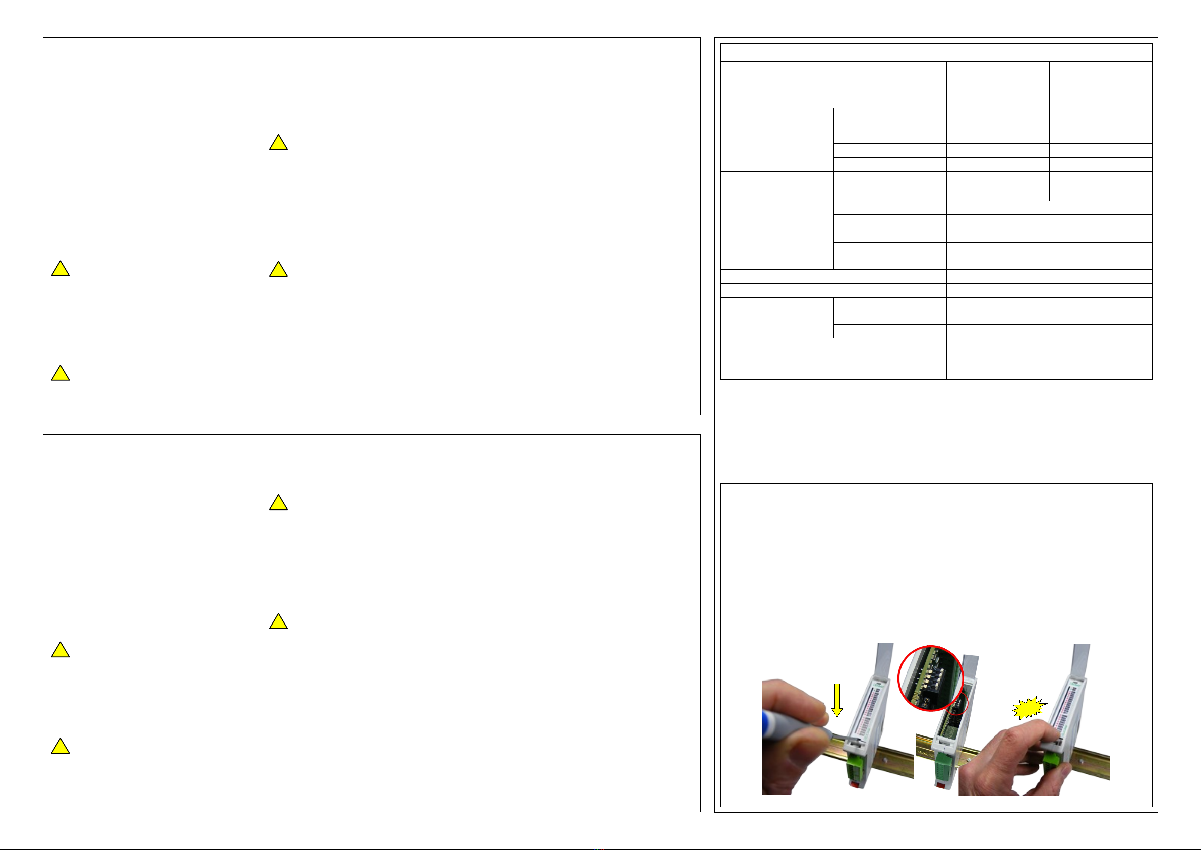
Nella figura sottostante sono indicate le operazioni da seguire per
lo smontaggio ed il successivo rimontaggio del frontalino
anteriore.
•Aprire il coperc io anteriore,
•Far leva nella parte sottostante con un cacciavite
•Settare il DIP switc interno per l'indirizzo desiderato
•Rimontare il frontalino inserendolo prima nella parte in
alto e, successivamente, premere nella parte in basso
fino allo scatto.
In t e figure below are s own t e operations to follow to remove
and remount t e front panel.
•Open t e front cover
•Insert a screwdriver in t e bottom ole of t e front
panel and move as indicated.
•Set-up t e internal DIP switc according to t e
desired address
•Reassemble t e front panel inserting t e top first and
t en, press on t e bottom until t e click.
Smontaggio e rimontaggio del frontalino
Front panel removing and reassembling
!
!
!
!
!
!
!
!
click
Other Elsist Control Unit manuals


Popular Control Unit manuals by other brands


Continental Disc Corporation
Continental Disc Corporation SANITRX HPX installation instructions

Honeywell
Honeywell R7284B installation instructions

Johnson Controls
Johnson Controls VP140 installation guide

Graco
Graco Cleanshot 244162 instructions

Humminbird
Humminbird HICP200 Instructions for use

steute
steute SRM 21 Multi Mounting and wiring instructions


