manuals.online logo
Brands
  1. Home
  2. •
  3. Brands
  4. •
  5. elsner elektronik
  6. •
  7. Accessories
  8. •
  9. elsner elektronik KNX R sl User manual

elsner elektronik KNX R sl User manual

Precipitation Sensor KNX R sl 1
Precipitation Sensor KNX R sl • Version: 14.04.2020 • Technical changes and errors excepted. • Elsner Elektronik GmbH • Sohlengrund 16 • 75395 Ostelsheim • Germany • www.elsner-elektronik.de • Technical Service: +49 (0) 7033 / 30945-250
EN
KNX R sl
Precipitation Sensor
1. Description
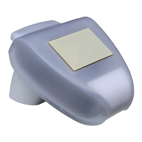
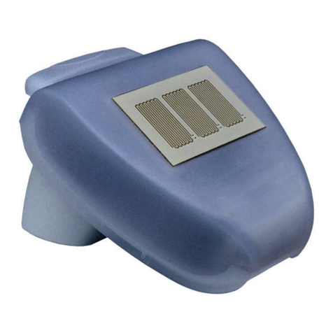
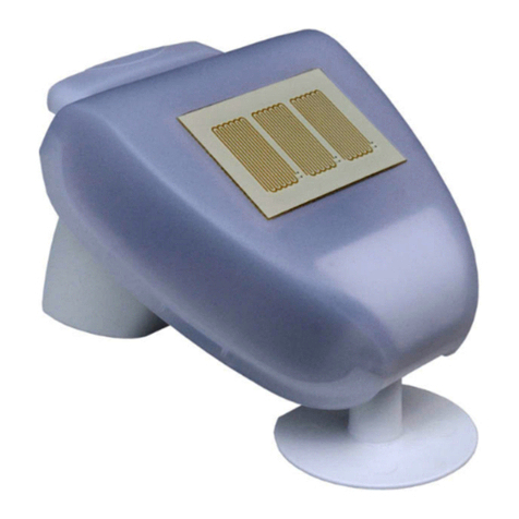
The Precipitation Sensor KNX R sl for the KNX building bus system detects pre-
cipitation. Two switching outputs, AND logic gates and OR logic gates are available.
The compact housing of the KNX R sl accommodates the sensors, evaluation cir-
cuits and bus-coupling electronics.
Functions:
•Precipitation detection: The sensor surface is heated, so that only drops
and flakes are recognised as precipitation, but not mist or dew. When the rain
or snow stops, the sensor is soon dry again and the precipitation warning
ends
•2 switching outputs (communication objects)
•4 AND and 4 OR logic gates, each with 4 inputs. All switching events as
well as 16 logic inputs (in the form of communications objects) can be used
as inputs for the logic gates. The output of each gate can be configured
optionally as 1-bit or 2 x 8-bit
Configuration is made using the KNX software ETS. The product file can be dow-
nloaded from the Elsner Elektronik website on www.elsner-elektronik.de in the
“Service” menu.
1.0.1. Deliverables
• Sensor
• Connection cable approx. 3 m, with plug
• Surface-mounted junction box (IP 55, not weatherproof)
• Worm drive hose clip for pole mounting (Ø 40-60 mm)
• 4×50 mm stainless steel roundhead screws and 6×30 mm dowels for wall
mounting. Use fixing materials that are suitable for the base!
1.1. Technical specification
The product conforms with the provisions of EU directives.
2. Installation and start-up
2.1. Installation notes
Installation, testing, operational start-up and troubleshooting should
only be performed by an electrician.
CAUTION!
Live voltage!
There are unprotected live components inside the device.
• National legal regulations are to be followed.
• Ensure that all lines to be assembled are free of voltage and take
precautions against accidental switching on.
• Do not use the device if it is damaged.
• Take the device or system out of service and secure it against
unintentional use, if it can be assumed, that risk-free operation is
no longer guaranteed.
The device is only to be used for its intended purpose. Any improper modification
or failure to follow the operating instructions voids any and all warranty and gua-
rantee claims.
After unpacking the device, check it immediately for possible mechanical damage.
If it has been damaged in transport, inform the supplier immediately.
The device may only be used as a fixed-site installation; that means only when as-
sembled and after conclusion of all installation and operational start-up tasks and
only in the surroundings designated for it.
Elsner Elektronik is not liable for any changes in norms and standards which may
occur after publication of these operating instructions.
2.2. Installation location
Select an installation position on the building where the sensor can measure rain
without hindrance. No structural elements should be mounted above the weather
station, from which water could continue to drop on the precipitation sensor even
after it has stopped raining or snowing.
The mounting position must be selected so that the precipitation sensor cannot be
touched by persons.
2.3. Position of the rain sensor
2.4. Sensor assembly
2.4.1. Attaching the mount
First mount the bracket for wall or pole mounting. To do this, loosen the screw con-
nection of the holder with a cross-headed screwdriver.
Wall mounting
Pole mounting
The device is mounted to the pole with the enclosed clamp.
Housing Plastic
Colour White / Translucent
Assembly Surface mount
Protection category IP 44
Dimensions approx. 62 × 55 × 155 (W × H × D, mm)
Weight approx. 80 g
Ambient temperature Operation -25…+85°C, storage -30…+85°C
Auxiliary supply 20...32 V DC.
An appropriate power supply unit can be pur-
chased from Elsner Elektronik.
Auxiliary current at 24V DC: max. 90 mA
Bus current max. 10 mA
Data output KNX +/-
BCU type Integrated microcontroller
PEI type 0
Group addresses max. 254
Assignments max. 254
Communication
objects
54
Technical specifications and installation instructions
Item number 70165
Fig. 1
The device must be attached to a ver-
tical wall (or a pole).
wall
or
pole
90°
Fig. 2
The device must be attached to a ver-
tical wall (or a pole).
Place the supply line in a loop before
leading it into the wall or junction box.
This will allow rain to drip off and not
drain into the wall or box.
Wall
or
pole
90°
Fig. 3
The device must be mounted in the
horizontal (transverse) direction.
Horizontale
1 Precipitation sensor (Area with
conductive tracks)
1
Fig. 4
Fig. 5 Front view
Screw the holder to the wall with two
screws. Use fixing materials (dowels,
screws) that are suitable for the base.
Make sure that the arrows point up-
wards.
Hole distance 30 mm
Fig. 6 Botttom view
Insert the clamp through the recess in
the bracket. Tighten the clamp on the po-
le.
Make sure that the arrows point up-
wards.
Pole
Precipitation Sensor KNX R sl 2
Precipitation Sensor KNX R sl • Version: 14.04.2020 • Technical changes and errors excepted. • Elsner Elektronik GmbH • Sohlengrund 16 • 75395 Ostelsheim • Germany • www.elsner-elektronik.de • Technical Service: +49 (0) 7033 / 30945-250
2.4.2. Fitting and connecting the device
1. Slide the device onto the mounting from above.
2. Tighten the screw of the mounting to secure the device.
3. Screw the M8 connector of the connection cable to the connection socket on the
bottom of the device.
Connect the loose end of the connection cable to the KNX bus and auxiliary voltage.
Use the supplied connection box and the terminals.
2.5. Instructions for assembly and initial start-up
After the auxiliary voltage has been applied, the device will enter an initialisation
phase lasting a few seconds. During this phase no information can be received or
sent via the bus.
3. Addressing the equipment
The equipment is delivered ex works with the bus address 15.15.255. You program
a different address in the ETS by overwriting the address 15.15.255 or teach the de-
vice using the programming button.
The programming button can be reached through the opening on the underside of
the housing; it is recessed by approx. 15 mm. Use a thin object to reach the key, e. g.
a 1.5 mm² wire.
4. Maintenance
WARNING!
Risk of injury caused by components moved automatically!
The automatic control can start system components and place people
in danger (e.g. moving windows/awnings if a rain/wind alarm has been
triggered while cleaning).
• Always isolate the device from the mains for servicing and
cleaning.
The device must regularly be checked for dirt twice a year and cleaned if necessary.
In case of severe dirt, the sensor may not work properly anymore.
ATTENTION
The device can be damaged if water penetrates the housing.
• Do not clean with high pressure cleaners or steam jets.
KNX bus: Auxiliary voltage:
+red
-black
+ yellow
-white
3
2
1
Fig. 7
1
Fig. 8
1 Programming LED
(under the semi-trans-
parent lid)
2 Programming button
for teaching the de-
vice
2
bottom side top side

This manual suits for next models

1

Other elsner elektronik Accessories manuals

elsner elektronik 20550 User manual

elsner elektronik

elsner elektronik 20550 User manual

elsner elektronik KNX L Guide

elsner elektronik

elsner elektronik KNX L Guide

elsner elektronik Sewi KNX L Guide

elsner elektronik

elsner elektronik Sewi KNX L Guide

elsner elektronik KNX L User manual

elsner elektronik

elsner elektronik KNX L User manual

elsner elektronik KNX VOC/TH-UP Touch User manual

elsner elektronik

elsner elektronik KNX VOC/TH-UP Touch User manual

elsner elektronik TH-UP basic User manual

elsner elektronik

elsner elektronik TH-UP basic User manual

elsner elektronik KNX B8-TH Guide

elsner elektronik

elsner elektronik KNX B8-TH Guide

elsner elektronik KNX T-L-Pr-UP Touch Guide

elsner elektronik

elsner elektronik KNX T-L-Pr-UP Touch Guide

elsner elektronik WGTH-UP User manual

elsner elektronik

elsner elektronik WGTH-UP User manual

elsner elektronik WG AQS/TH-UP User manual

elsner elektronik

elsner elektronik WG AQS/TH-UP User manual

elsner elektronik KNX AQS/TH-B-UP User manual

elsner elektronik

elsner elektronik KNX AQS/TH-B-UP User manual

elsner elektronik KNX W sl Guide

elsner elektronik

elsner elektronik KNX W sl Guide

elsner elektronik Vari KNX 3L-TH-D GPS Guide

elsner elektronik

elsner elektronik Vari KNX 3L-TH-D GPS Guide

elsner elektronik KNX RW sl User manual

elsner elektronik

elsner elektronik KNX RW sl User manual

elsner elektronik WGTH-UP User manual

elsner elektronik

elsner elektronik WGTH-UP User manual

elsner elektronik WG AQS/TH gl User manual

elsner elektronik

elsner elektronik WG AQS/TH gl User manual

elsner elektronik KNX RW User manual

elsner elektronik

elsner elektronik KNX RW User manual

elsner elektronik KNX T-B-UP User manual

elsner elektronik

elsner elektronik KNX T-B-UP User manual

elsner elektronik KNX R Guide

elsner elektronik

elsner elektronik KNX R Guide

elsner elektronik KNX TH-UP Touch User manual

elsner elektronik

elsner elektronik KNX TH-UP Touch User manual

elsner elektronik KNX LW 70128 User manual

elsner elektronik

elsner elektronik KNX LW 70128 User manual

elsner elektronik 30170 User manual

elsner elektronik

elsner elektronik 30170 User manual

elsner elektronik KNX AQS TH-B-UP Guide

elsner elektronik

elsner elektronik KNX AQS TH-B-UP Guide

elsner elektronik P04i-W User manual

elsner elektronik

elsner elektronik P04i-W User manual

Popular Accessories manuals by other brands

PSI Woodworking PKCP80 Series quick start guide

PSI Woodworking

PSI Woodworking PKCP80 Series quick start guide

Hytronik HIR28DCVFC Installation and instruction manual

Hytronik

Hytronik HIR28DCVFC Installation and instruction manual

Boonton 4400A Manual addendum

Boonton

Boonton 4400A Manual addendum

Gared Sports Playmaker TOSS BACK Assembly manual

Gared Sports

Gared Sports Playmaker TOSS BACK Assembly manual

KROHNE SMARTPAT COND 1200 Handbook

KROHNE

KROHNE SMARTPAT COND 1200 Handbook

Velleman CTC1000PIR user manual

Velleman

Velleman CTC1000PIR user manual

Promate PolyMax-10C user guide

Promate

Promate PolyMax-10C user guide

D-Link DUB-CR200 installation guide

D-Link

D-Link DUB-CR200 installation guide

M-Audio Profire 610 user guide

M-Audio

M-Audio Profire 610 user guide

Imetec R1501 Instructions for use

Imetec

Imetec R1501 Instructions for use

SONBEST SM2130B-H2 user manual

SONBEST

SONBEST SM2130B-H2 user manual

DYNATEK DS6-2 installation instructions

DYNATEK

DYNATEK DS6-2 installation instructions

Scooterpac Canopy user manual

Scooterpac

Scooterpac Canopy user manual

Focusrite Scarlett 2i2 user guide

Focusrite

Focusrite Scarlett 2i2 user guide

Dini Argeo 3590EGT Series user manual

Dini Argeo

Dini Argeo 3590EGT Series user manual

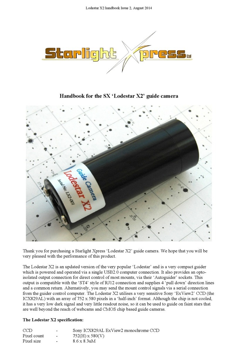
Starlight Xpress Lodestar X2 Handbook Guide

Starlight Xpress

Starlight Xpress Lodestar X2 Handbook Guide

Aeotec ZW162 user guide

Aeotec

Aeotec ZW162 user guide

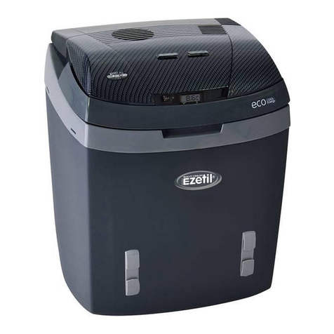
Ezetil E3000 operating instructions

Ezetil

Ezetil E3000 operating instructions

manuals.online logo
manuals.online logoBrands
  • About & Mission
  • Contact us
  • Privacy Policy
  • Terms and Conditions

Copyright 2025 Manuals.Online. All Rights Reserved.