manuals.online logo
Brands
  1. Home
  2. •
  3. Brands
  4. •
  5. elsner elektronik
  6. •
  7. Power Supply
  8. •
  9. elsner elektronik KNX PS640 4U User manual

elsner elektronik KNX PS640 4U User manual

08.06.2021
Reservado el derecho a realizar modificaciones técnicas y a errores. / Technical changes and errors excepted.
Elsner Elektronik GmbH • Sohlengrund 16 • 75395 Ostelsheim • Deutschland • www.elsner-elektronik.de • Service: +49 (0) 7033 / 30945-250
Fuente de alimentación de tensión de bus KNX/auxiliar
Instrucciones de instalación
Instrucciones de seguridad y de uso
El archivo del producto (aplicación ETS 5) se puede descargar en el menú «Servicio» del sitio
web de Elsner Elektronik en www.elsner-elektronik.de.
Los trabajos de instalación y puesta en servicio deben ser llevados a cabo exclusivamente
por un electricista profesional.
¡PELIGRO!
¡Peligro de muerte debido a la presencia de tensión eléctrica (tensión de red)!
En el interior del dispositivo hay piezas bajo tensión sin aislamiento.
• Ponga en funcionamiento únicamente dispositivos que no estén averiados.
• Cumpla las directrices, especificaciones y disposiciones locales vigentes en materia de
instalaciones eléctricas.
• Apague inmediatamente el dispositivo o la instalación y protéjalos para impedir que se puedan
activar de forma accidental cuando considere que no se puede garantizar un funcionamiento
exento de peligro.
Utilice este dispositivo exclusivamente para la automatización de edificios y tenga en cuenta las
instrucciones de uso. En caso de que se haga un uso incorrecto del dispositivo, se modifique de
forma indebida o no se observen las instrucciones de uso, se perderán todos los derechos de ga-
rantía.
Utilice el dispositivo únicamente en una instalación fija, es decir, solo cuando está montado y tras
haber finalizado todas las labores de instalación y puesta en marcha, y solo en el entorno para el
que está previsto.
Descripción
La fuente de alimentación KNX PS640 4U es una unidad de alimentación de tensión de bus
KNX de 640 mA y se utiliza para alimentar una línea de par trenzado (TP) en el sistema de bus KNX.
Además, la KNX PS640 4U dispone de una salida adicional no limitada para el suministro de co-
rriente auxiliar, por ejemplo, para alimentar una segunda línea (solo con un limitador adicional).
Con esta salida adicional también se pueden operar los dispositivos KNX que necesitan una segun-
da tensión de alimentación.
Ambas salidas están protegidas contra sobrecargas y cortocircuitos. El bus KNX se puede restable-
cer pulsando un botón. Un LED indica la desconexión del bus durante el restablecimiento. Los LED
de la tensión KNX y la corriente de salida señalizan el funcionamiento normal y la sobrecarga.
Volumen de suministro
• Fuente de alimentación
• Conector KNX (rojo/negro) y conector de tensión auxiliar (blanco/amarillo)
Instalación
Lugar de montaje y preparación
• Instale el dispositivo exclusivamente en entornos secos. Protéjalo para que no se humedezca, se
ensucie o se dañe.
• Asegúrese de que se pueda acceder siempre al dispositivo para su uso e inspección
• No abra la carcasa del dispositivo
• Utilice una herramienta adecuada para el montaje de conformidad con IEC60715
• Instale el dispositivo exclusivamente en armarios de distribución o cajas cerradas y en un carril
DIN adecuado (TS35). Cubra por completo las piezas conductoras de corriente. de manera que no
sea posible retirar la cubierta sin utilizar una herramienta. El armario de distribución ha de garan-
tizar una protección de contacto completa
Conexión
• La conexión se lleva a cabo mediante terminales roscados y de bus
• Conecte la línea de bus KNX, igual que en todas las conexiones KNX normales, con un cable de
bus KNX desnudo y un conector KNX TP. No dañe los aislamientos eléctricos al conectar los com-
ponentes
Funcionamiento
En las instalaciones de red KNX, la KNX PS640 4U alimenta una línea de par trenzado KNX. La
entrada de la base de datos del ETS (plantilla) de KNX PS640 4U está disponible a partir de la
ES
KNX PS640 4U
70146
Fig. 1
ES Estructura del dispositivo
1 Tensión de bus VBUS
verde: VBUS de 28…31 V DC
[apagado]: VBUS está fuera de
este rango
2 Corriente de salida IOUT
[apagado]: IOUT < 900 mA
rojo: IOUT > 900 mA (sobrecar-
ga)
3 Restablecimiento del bus KNX
rojo: se está restableciendo la lí-
nea de bus KNX
A Conexión a la red
B Botón de reinicio
C Conexión de la tensión auxiliar
D Conexión KNX TP
EN Device structure
1 Bus voltage VBUS
green: VBUS is 28…31 V DC
[off]: VBUS is out of this range
2 Output current IOUT
[off]: IOUT < 900 mA
red: IOUT > 900 mA (Overload)
3 KNX bus reset
red: Restart of the KNX bus line
is running
A Supply voltage terminals
B Reset button
C Aux output connector
D KNX TP connector
Power Supply KNX bus/Auxiliary Voltage
Installation instructions
Safety and operating instructions
Product file (ETS 5 application) can be downloaded from the Elsner Elektronik website on
www.elsner-elektronik.de in the “Service” menu.
Installation and operational start-up should only be performed by an electrician.
DANGER!
Risk to life from live voltage (mains voltage)!
There are unprotected live components inside the device.
• Only put undamaged devices into operation.
• Comply with the locally applicable directives, regulations and provisions for electrical installation.
• Immediately take the device or system out of service and secure it against unintentional switch-
on if risk-free operation is no longer guaranteed.
Use the device exclusively for building automation and observe the operating instructions. Impro-
per use, modifications to the device or failure to observe the operating instructions will invalidate
any warranty or guarantee claims.
Operate the device only as a fixed-site installation, i.e. only in assembled condition and after con-
clusion of all installation and operational start-up tasks, and only in the surroundings designated
for it.
Description
The Power Supply KNX PS640 4U is a 640 mA KNX bus power supply to supply one TP line of
a KNX system with power. The KNX PS640 4U also features an additional unchoked output. This
auxiliary output can be used, for example, to supply a second line (only with additional choke). De-
vices which require a second supply voltage can be supplied.
Both outputs are overload-proof and short circuit protected. The KNX bus can be reset by push-but-
ton. Bus disconnection during reset is indicated by a LED. Further LEDs, for KNX bus voltage and
total output current, indicate normal operation and overload.
Scope of delivery
• Power Supply System
• KNX terminal (red/black) and auxiliary voltage terminal (white/yellow)
Installation
Installation location and preparation
• Installation only in dry locations. Protect the device from moisture, dirt and damage
• Accessibility of the device for operation and visual inspection must be provided
• The housing of the device must not be opened
• For mounting use an appropriate equipment according to IEC60715
• Installation only in distribution boards and enclosed housings. Installation only on a 35 mm DIN
rail (TH35). Terminals and metal parts under current must be completely covered. It must be not
possible to remove the cover without aid of a tool. Contact protection must be provided through
the control cabinet
Connection
• Connections are made by screw and bus terminals
• Connect the KNX bus line as for common KNX bus connections with a KNX bus cable, to be strip-
ped and plugged into the KNX TP connector. Do not damage electrical insulations when connec-
ting
Operation
In KNX network installations KNX PS640 4U supplies one KNX TP line. The KNX PS640 4U's
ETS (dummy) database entry is available for ETS4 and upward. The database without parameters
and without communication objects can be added to an ETS project as usual.
EN
08.06.2021
Reservado el derecho a realizar modificaciones técnicas y a errores. / Technical changes and errors excepted.
Elsner Elektronik GmbH • Sohlengrund 16 • 75395 Ostelsheim • Deutschland • www.elsner-elektronik.de • Service: +49 (0) 7033 / 30945-250
Suministro: Power input:
230 V ±15 %, 50 Hz Tensión de red Mains voltage
0.9 W Potencia perdida (abierto) Leakage loss (open-circuited)
4.3 W Potencia perdida (normal) Leakage loss (normal)
22.9 W Potencia necesaria (normal) Power consumption (normal)
44.5 W Potencia necesaria (máx., sobrecarga) Power consumpt. (max., overload)
Carcasa: Housing:
RAL 9018 Carcasa de plástico PA66, de color blanco Plastic PA66 housing, Housing colour white
94 mm × 72 mm × 71 mm Dimensiones (alto × ancho × profundidad), 4 módulos de 18 mm cada uno Dimensions (H × W × D), 4 modules at 18 mm
(TH35) Montaje (IEC60715) en carril de 35 mm (DIN) Mounting (IEC60715) 35 mm top-hat rail
0.3…2.5 mm² Conexión a la red con bornes roscados (par de apriete máx. 0,4 Nm) Mains voltage connection Screw terminals (max. torque 0.4 Nm)
Ø 0.6...0.8 mm Conexión de bus KNX conector KNX (rojo/negro), sin tornillos, para cables de un solo hilo KNX bus connection KNX TP connector (red/black), screwless, for single-core cable
Ø 0.6...0.8 mm Conexión (de tensión auxiliar) AUX conector KNX (blanco/amarillo), sin tornillos, para cables de
un solo hilo
AUX output connection KNX TP connector (white/yellow), screwless, for single-core cable
206 g Peso Weight
Condiciones ambientales: Environmental conditions:
-5…+45 °C Temperatura de trabajo Operating temperature
-20…+70 °C Temperatura de almacenamiento Storage temperature
5...93 % Humedad ambiente (sin condensación) Ambient humidity (non-condensing)
Potencia de salida: Power output:
28…31 V SELV Tensión de bus KNX KNX output voltage
28…31 V SELV Tensión auxiliar AUX AUX output voltage
640 mA Corriente nominal Rated current
1.2 A Corriente máxima (total) Maximum current (total output)
> 100 ms Tiempo de solape en caso de corte de corriente Mains failure bridging time
Seguridad eléctrica: Electrical safety:
2 Grado de contaminación (IEC60664) Pollution degree (IEC60664)
III Categoría de sobretensión (IEC60664) Overvoltage category (IEC60664)
ES Esquema de instalación
EN Installation scheme
Fig. 2
versión ETS4. La base de datos sin parámetros ni objetos de comunicación se puede añadir como
siempre en el proyecto ETS.
Aplicación
KNX PS640 4U no tiene parámetros ni objetos de comunicación. Tampoco se puede cargar una
dirección individual en el dispositivo.
Función de restablecimiento del bus KNX
El «restablecimiento del bus KNX» se efectúa pulsando el botón de «Reset». Cuando se restaura el
bus, el dispositivo desconecta la línea de bus de la salida a la que está conectado y provoca un cor-
tocircuito. El LED 3 (restablecimiento del bus KNX) se enciende en color rojo y se apaga cuando ha
finalizado la operación de restablecimiento del bus. El LED 1 continúa encendido en color verde.
Los dispositivos conectados a la línea de bus se reinician durante el restablecimiento del bus.
Se recomienda pulsar el botón «Reset» durante al menos 20 segundos.
• Restablecimiento mediante botón:
el botón «Reset» activa el restablecimiento del bus KNX. Pulse el botón «Reset» del dispositivo
para restaurar la línea de bus KNX.
• Restablecimiento mediante desconexión de los bornes:
si se retiran los terminales de bus KNX, se desconecta toda la línea de bus.
Mantenimiento
Este dispositivo no necesita mantenimiento. En caso necesario, límpielo con un trapo seco
Eliminación
Tras el uso, el aparato deberá eliminarse o depositarse en el punto de reciclaje conforme a las dis-
posiciones vigentes. ¡No lo deposite en la basura doméstica!
Datos técnicos
Este producto cumple con las normas de las directivas europeas.
Application
KNX PS640 4U has no parameters and no communication objects. An individual Address cannot
be downloaded to the device.
KNX Bus Reset Function
A "KNX Bus Reset" is carried out by pressing the Reset Button. During a reset, the device discon-
nects the bus line from the supplying output and induces a short circuit. LED 3 (KNX Bus Reset)
lights up red and goes off after the reset process is accomplished. LED 1 keeps on lighting green.
Devices connected to the bus line restart during the reset process.
It is recommended to press the Reset Button for at least 20 seconds.
• Reset by push-button:
The Reset Button activates the KNX Bus Reset. Press the Reset Button on the device to reset the
KNX bus line.
• Reset by disconnection:
Removing the KNX bus terminals disconnects the entire bus line.
Maintenance
The device needs no maintenance. If necessary, the device can be cleaned with a dry cloth
Disposal
After use, the device must be disposed of or recycled in accordance with the legal regulations. Do
not dispose of it with the household waste!
Technical data
The product conforms to the conditions of the EU Directives.

This manual suits for next models

1

Other elsner elektronik Power Supply manuals

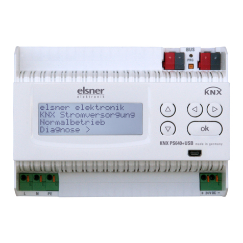
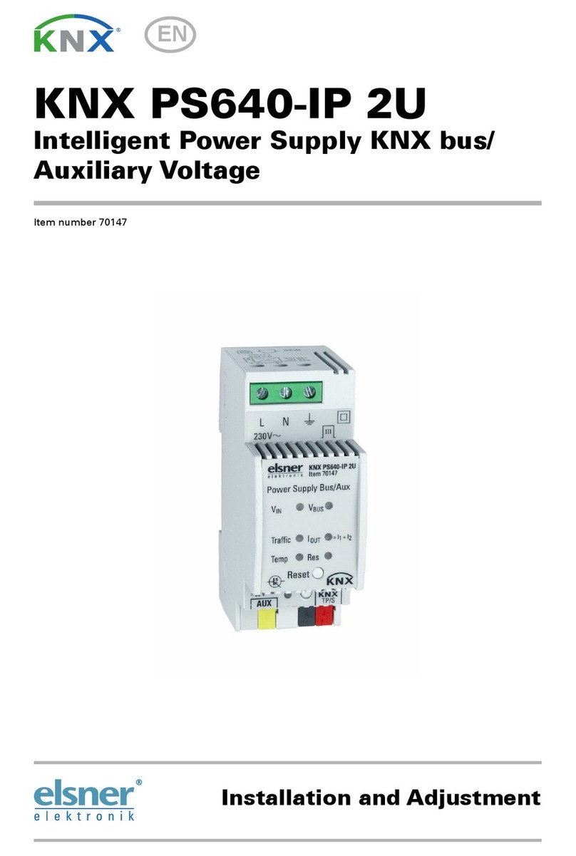
elsner elektronik KNX PS640-IP 2U User manual

elsner elektronik

elsner elektronik KNX PS640-IP 2U User manual

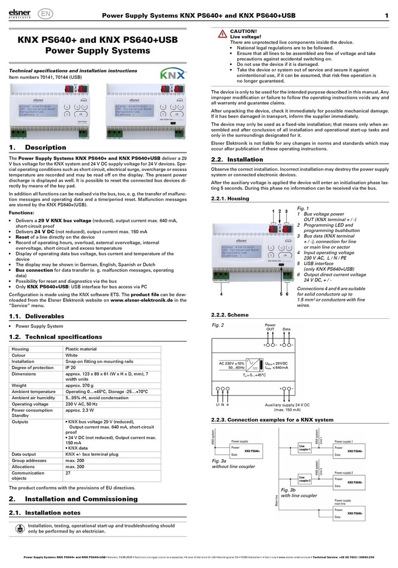
elsner elektronik KNX PS640+ Guide

elsner elektronik

elsner elektronik KNX PS640+ Guide

elsner elektronik KNX PS640+ Guide

elsner elektronik

elsner elektronik KNX PS640+ Guide

elsner elektronik KNX PS640 Instruction manual

elsner elektronik

elsner elektronik KNX PS640 Instruction manual

elsner elektronik KNX PS640 User manual

elsner elektronik

elsner elektronik KNX PS640 User manual

elsner elektronik KNX PS640+ User manual

elsner elektronik

elsner elektronik KNX PS640+ User manual

elsner elektronik KNX PS640-IP 2U User manual

elsner elektronik

elsner elektronik KNX PS640-IP 2U User manual

elsner elektronik KNX PS640-IP 2U Guide

elsner elektronik

elsner elektronik KNX PS640-IP 2U Guide

Popular Power Supply manuals by other brands

WAGO Pro 2 product manual

WAGO

WAGO Pro 2 product manual

HP BENCH Series Operating and service manual

HP

HP BENCH Series Operating and service manual

Teledyne T3PS3000 quick start guide

Teledyne

Teledyne T3PS3000 quick start guide

Videotec OHEPS19B instruction manual

Videotec

Videotec OHEPS19B instruction manual

FiveFish Audio PSU-2448Plus+ Assembly guide

FiveFish Audio

FiveFish Audio PSU-2448Plus+ Assembly guide

VOLTCRAFT FPS-1132 operating instructions

VOLTCRAFT

VOLTCRAFT FPS-1132 operating instructions

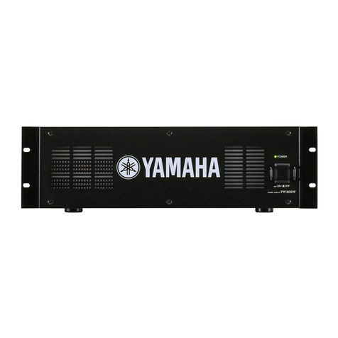
Yamaha PW800W owner's manual

Yamaha

Yamaha PW800W owner's manual

Bryston MPS-2 owner's manual

Bryston

Bryston MPS-2 owner's manual

Alpha Technologies Alpha Outback Energy AlphaCap-665 Installation & operation manual

Alpha Technologies

Alpha Technologies Alpha Outback Energy AlphaCap-665 Installation & operation manual

Antminer APW9 Maintenance Guide

Antminer

Antminer APW9 Maintenance Guide

National Instruments PXI-4110 CALIBRATION PROCEDURE

National Instruments

National Instruments PXI-4110 CALIBRATION PROCEDURE

Tektronix PS 5004 instruction manual

Tektronix

Tektronix PS 5004 instruction manual

Audiocom MS-2002 user manual

Audiocom

Audiocom MS-2002 user manual

Lütze CPSB1-120-24 E instructions

Lütze

Lütze CPSB1-120-24 E instructions

Pulsar PSBOC351225 manual

Pulsar

Pulsar PSBOC351225 manual

Magnetek PS-A10H installation manual

Magnetek

Magnetek PS-A10H installation manual

HP A3550A - High Availability Disk Arrays Model 20 Storage... installation guide

HP

HP A3550A - High Availability Disk Arrays Model 20 Storage... installation guide

Danfoss AK-PS150 Instructions for use

Danfoss

Danfoss AK-PS150 Instructions for use

manuals.online logo
manuals.online logoBrands
  • About & Mission
  • Contact us
  • Privacy Policy
  • Terms and Conditions

Copyright 2025 Manuals.Online. All Rights Reserved.