elsner elektronik KNX PS640-IP 2U Guide

KNX PS640-IP 2U
Intelligent Power Supply KNX bus/
Auxiliary Voltage
Item number 70147
EN
Installation and Adjustment


1 Content
Elsner Elektronik GmbH • Sohlengrund 16 • 75395 Ostelsheim • Germany
Intelligent Power Supply KNX PS640-IP 2U • from application 1.0
Status: 21.09.2021 • Technical changes and errors excepted.
1. Safety and usage instructions ............................................................. 3
2. Description ........................................................................................... 3
3. Commissioning .................................................................................... 4
3.1. Addressing of the device at the bus ....................................................................... 4
3.2. Default settings ......................................................................................................... 4
4. Operation ............................................................................................. 5
4.1. Device/Busline Diagnostics Application ................................................................. 5
4.2. Diagnosis .................................................................................................................. 5
4.2.1. Measurement Sources ................................................................................. 5
4.2.2. Event Counters .............................................................................................. 5
4.2.3. Event Counter Reset ..................................................................................... 6
4.3. Parameter Structure for Measurement Sources .................................................... 6
4.4. Programming ............................................................................................................ 7
4.4.1. Programming Button .................................................................................... 7
4.4.2. Individual Address Assignment ................................................................... 7
4.5. KNX Bus Reset Function .......................................................................................... 8
5. Transfer protocol ............................................................................... 10
5.1. List of all communication objects ......................................................................... 10
6. ETS Database Parameters .................................................................. 16
6.1. General .................................................................................................................... 16
6.2. Measurements ........................................................................................................ 16
6.3. Maximum Tracking ................................................................................................ 18
6.4. Telegram Traffic ..................................................................................................... 19
6.5. Error Counters ........................................................................................................ 20
6.6. Operational Counters ............................................................................................. 20
6.7. Alarm 1, 2, 3, 4 ........................................................................................................ 21

2 Clarification of signs
This manual is amended periodically and will be brought into line with new software
releases. The change status (software version and date) can be found in the contents footer.
If you have a device with a later software version, please check
www.elsner-elektronik.de in the menu area "Service" to find out whether a more up-to-
date version of the manual is available.
Clarification of signs used in this manual
Safety advice.
Safety advice for working on electrical connections, components,
etc.
DANGER! ... indicates an immediately hazardous situation which will lead to
death or severe injuries if it is not avoided.
WARNING! ... indicates a potentially hazardous situation which may lead to
death or severe injuries if it is not avoided.
CAUTION! ... indicates a potentially hazardous situation which may lead to
trivial or minor injuries if it is not avoided.
ATTENTION! ... indicates a situation which may lead to damage to property if it is
not avoided.
ETS In the ETS tables, the parameter default settings are marked by
underlining.

3 Safety and usage instructions
Intelligent Power Supply KNX PS640-IP 2U • Version: 21.09.2021 • Technical changes and errors excepted.
1. Safety and usage instructions
Installation, testing, operational start-up and troubleshooting should
only be performed by an authorised electrician.
DANGER!
Risk to life from live voltage (mains voltage)!
There are unprotected live components inside the device.
• Inspect the device for damage before installation. Only put undamaged
devices into operation.
• Comply with the locally applicable directives, regulations and provisions for
electrical installation.
• Immediately take the device or system out of service and secure it against
unintentional switch-on if risk-free operation is no longer guaranteed.
Use the device exclusively for building automation and observe the operating instruc-
tions. Improper use, modifications to the device or failure to observe the operating in-
structions will invalidate any warranty or guarantee claims.
Operate the device only as a fixed-site installation, i.e. only in assembled condition and
after conclusion of all installation and operational start-up tasks, and only in the sur-
roundings designated for it.
Elsner Elektronik is not liable for any changes in norms and standards which may occur
after publication of these operating instructions.
For information on installation, maintenance, disposal, scope of
delivery and technical data, please refer to the installation
instructions.
2. Description
With a very small footprint of only 2 units (36 mm) the Intelligent Power Supply
KNX PS640-IP 2U with diagnosis is highly efficient and features an additional auxil-
iary power output (e.g. to support individual components). The device has one choked
and one non-choked output. The outputs are overload and short circuit protected. The
KNX PS640-IP 2U generates a voltage of 30 V DC and the integrated choke decouples
the KNX bus line from the 30 V DC auxiliary output. Any desired load distribution on
the outputs is possible. The LED display indicates the state of the power supply unit
and the bus line. The KNX bus reset can be triggered over the bus by a communication
object or directly at the device by a single button press. Internal parts of the device are
designed to ensure a long working life and work reliably also when the device temper-
ature increases.
Configuring can be done with the ETS. 36 communication objects are available. For di-
agnostic purposes bus voltage, output current, device temperature and times of oper-
ation are monitored. All details (number, duration) on events like short circuit, over-

4 Commissioning
Intelligent Power Supply KNX PS640-IP 2U • Version: 21.09.2021 • Technical changes and errors excepted.
load, load disconnection, device startup and KNX bus reset are easily accessible. The
data can be read out via the KNX bus. It can be sent on demand, periodically and after
a certain change in value. It can also be sent after an error event and on crossing a pre-
set threshold value. Number and duration of such over-threshold events are also avail-
able information. When the device returns to normal working condition (after KNX bus
reset, device startup, short circuit) info telegrams are sent automatically. Additionally,
extensive alarm and maximum tracking functionalities are available.
In this document, physically addressed telegrams are named Physical Telegrams.
In this document, group oriented telegrams are named Group Telegrams.
Functions:
• Slim 640 mA KNX power supply unit having only 2 M (36 mm)
• Cost reduction due to less space requirement
• Output overload and short circuit protected
• Additional unchoked auxiliary power output
• Device reset by on-device push button
• Remote reset function: reset via bus line by communication object
• Monitoring of output voltage, output current, telegram traffic and device
temperature
• Monitoring of events (threshold, device startup, KNX bus reset)
• Monitoring of output failures (due to overload, short circuit, mains power
outage)
• Configurable additional alarms
• Extensively configurable alarm/threshold functionality for further evaluation
• Switching of bus devices, electrical consumers or alarm indicators
• Informational readout: cyclic, on demand or after a pre-set change in value
• Device and bus line status indicated by six duo LED display
• Internal supply via externally-connected 230 V AC
• Database available for ETS4 and higher
• Installation on 35mm top-hat rails (DIN, TH35)
3. Commissioning
Configuration is made using the KNX software as of ETS 4. The product file can be
downloaded from the ETS online catalogue and the Elsner Elektronik website on
www.elsner-elektronik.de in the “Service” menu. There you will also find the pro-
duct manual.
3.1. Addressing of the device at the bus
The equipment is delivered with the individual address 12.12.255. This can be changed
via the ETS. A button and a control LED are located on the unit for this purpose.
3.2. Default settings
• All telegrams are blocked because the filter table is not defined
• The Manual Function switch-off time is 120 min

5 Operation
Intelligent Power Supply KNX PS640-IP 2U • Version: 21.09.2021 • Technical changes and errors excepted.
4. Operation
In network installations, KNX PS640-IP 2U supplies one KNX TP line and monitors
all relevant data. With its default settings the KNX PS640-IP 2U operates as is sup-
posed to.
4.1. Device/Busline Diagnostics Application
Communication objects are used to request device status and measurement values.
The measured values can be sent after request, after a certain change (measured value,
device status) and periodically. Here, a certain change of the measured value means
the difference between actual value and last sent value. Number and duration of over-
loads are stored. The same applies for the number of short circuits, device startups,
KNX bus resets and for the duration of load detachments. The total operating time of
the device and its operating time since last device startup are stored, too. Threshold
values can be set for the bus voltage (only in the additional alarms), total current, tele-
gram traffic and internal device temperature. Regarding maximum current values and
maximum device temperature values, a tracking period can be set. At the end of every
tracking period the maximum measured value can be sent on the bus or just be set as
value of the appropriate object. Four different Alarm tabs (see chapter 6.7.) can be used
to send an info telegram (containing "0" or "1") about over/under threshold events and
to switch other devices. After assignment of the measurement source ("Output cur-
rent", "Device temperature", "Output Voltage") each alarm can be configured individu-
ally.
4.2. Diagnosis
The diagnostic measurement sources and event counters can be activated and deacti-
vated. When activated, the device monitors the relevant values.
4.2.1. Measurement Sources
The bus voltage, bus current and internal device temperature are measured constantly.
The telegram traffic extent is determined additionally. For each of these measurement
sources a threshold value can be set. After setting the threshold value the threshold
type can be selected (limit undercut/limit exceeded) and the behaviour on alarm acti-
vation/deactivation can be configured. A maximum value tracking feature with pre-set-
table tracking period can also be activated.
4.2.2. Event Counters
For diagnosis purpose, event counters provide number and duration of overloads.
When there is a short circuit on the bus, the load will be disconnected from the output
automatically. Number of short circuits and duration of load detachment are available
details. The same applies for the number of KNX bus resets and of device startups, and
for operating times. Additional alarms also provide the number of a value being in the
threshold range and the duration of such event.

6 Operation
Intelligent Power Supply KNX PS640-IP 2U • Version: 21.09.2021 • Technical changes and errors excepted.
4.2.3. Event Counter Reset
Counters for total operating time and device startups cannot be reset. Other counters
for events can be reset by communication object. These counters (number and dura-
tion) are set to zero by writing a "1" to the communication object no. 33 "Counter reset".
The event counter of each individual alarm (1,2,3,4) is set to zero by writing a "0" to the
related communication object "Duration X" (objects no. 21, 24, 27, 30). Both number
and duration counters then will be reset.
4.3. Parameter Structure for Measurement Sourc-
es
On enabling a measurement source in the ETS tab "Measurements", the following pa-
rameter structure is available (exception: counters). An actual value can be sent over
the bus after a certain value change ("Sending difference") or after a pre-set time period
has elapsed ("Cyclic sending"). A value reaching the excess threshold range can be
used to send telegrams containing "1" or "0" ("Behaviour on alarm activation"). Leaving
this excess threshold range activates the "Behaviour on alarm deactivation". The addi-
tional alarms have an extended adjustment.
Table 1: Available Event Counters
Event Number Counter Duration Counter
Overload X X
Short Circuit X
Load Detached X
KNX Bus Reset X
Threshold Range X X
Operating Time
(total/since last startup)
X
Device Startup X

7 Operation
Intelligent Power Supply KNX PS640-IP 2U • Version: 21.09.2021 • Technical changes and errors excepted.
4.4. Programming
4.4.1. Programming Button
To download the desired Individual Address or an ETS setting the Programming But-
ton must be pressed first. Successive pressing the Programming Button will turn on
and off the Programming Mode. LED 7 lighting in red colour indicates Programming
Mode is active. When Programming Mode is active, ETS recognizes the device of inter-
est for downloading.
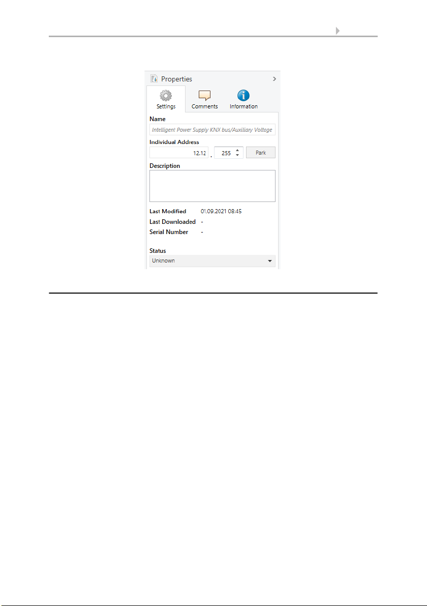
4.4.2. Individual Address Assignment
To configure the device an interface connection (IP, USB) to the KNX bus system is re-
quired. The device is supplied with the Individual Address 12.12.255. The KNX product
database entry (available for ETS4 and higher) can be downloaded from the website
and from the KNX Online Catalog.
With the ETS the Individual Address can be assigned to the device by setting the de-
sired address in the properties window of the ETS. After starting the ETS download
and then pressing the Programming Button the device restarts itself.
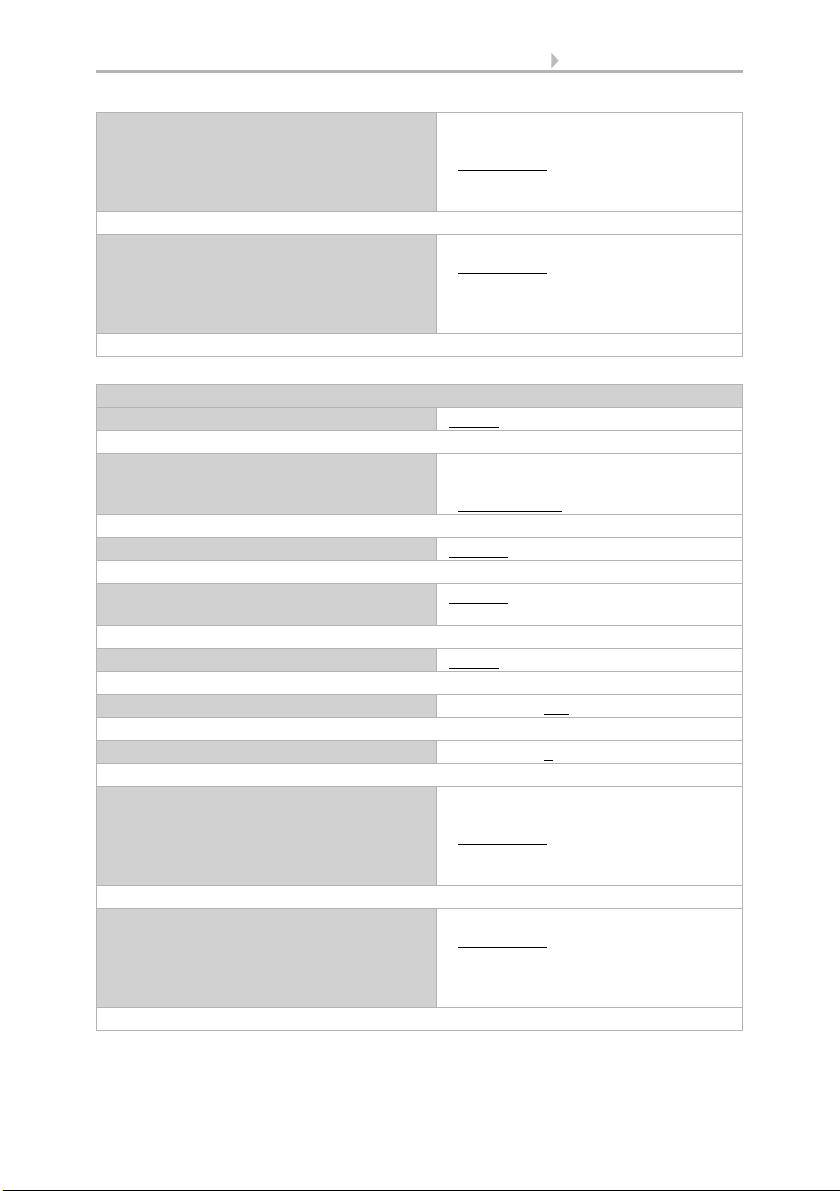
Table 2: General Menu Structure
ETS Parameter Explanation
Object type Selection of the datapoint type
Sending difference The actual value is sent when the difference between last sent
value and actual value reaches the pre-set difference
Cyclic sending The actual value is periodically sent
Alarm settings Enables/disables the threshold functionality and following
options
Threshold Crossing this limiting value executes the "Behaviour on alarm
activation" function
Hysteresis Passing the "Threshold"-"Hysteresis" value executes the
"Behaviour on alarm deactivation" function
Behaviour on alarm
activation
Set action on activation: Send a telegram or set the internal
object value
Behaviour on alarm
deactivation
Set action on deactivation: Send a telegram or set the internal
object value
8 Operation
Intelligent Power Supply KNX PS640-IP 2U • Version: 21.09.2021 • Technical changes and errors excepted.
4.5. KNX Bus Reset Function
During a bus reset, the device disconnects the entire bus line from the supplying out-
put and induces a short circuit for 20 seconds. LED 6 (KNX Bus Reset) lights up red and
goes off after the reset process is accomplished. Other LEDs are off. The devices con-
nected to the bus line restart during the reset process.
Bus Reset and Device Startup:
• Reset by push-button:
The Reset Button activates the KNX Bus Reset function. Press the Reset Button
on top of the device to reset the KNX bus line
• Reset by object:
A remote reset can be triggered by communication object no.16
• Reset by disconnection:
Removing the KNX bus terminals disconnects the entire bus line
• ETS programming:
When there was a mains power outage or after an ETS download, the KNX
PS640-IP 2U counts a device startup
A "KNX Bus Reset" is triggered after a reset by button press and after a reset by com-
munication object. A "Device Startup" takes place when there was a mains power out-
age or after programming the device. The number of "Short circuits" is counted only
by the counter that can be read out with communication object no.36 "Power supply is
on".
Fig. 1: ETS Properties Window

9 Operation
Intelligent Power Supply KNX PS640-IP 2U • Version: 21.09.2021 • Technical changes and errors excepted.
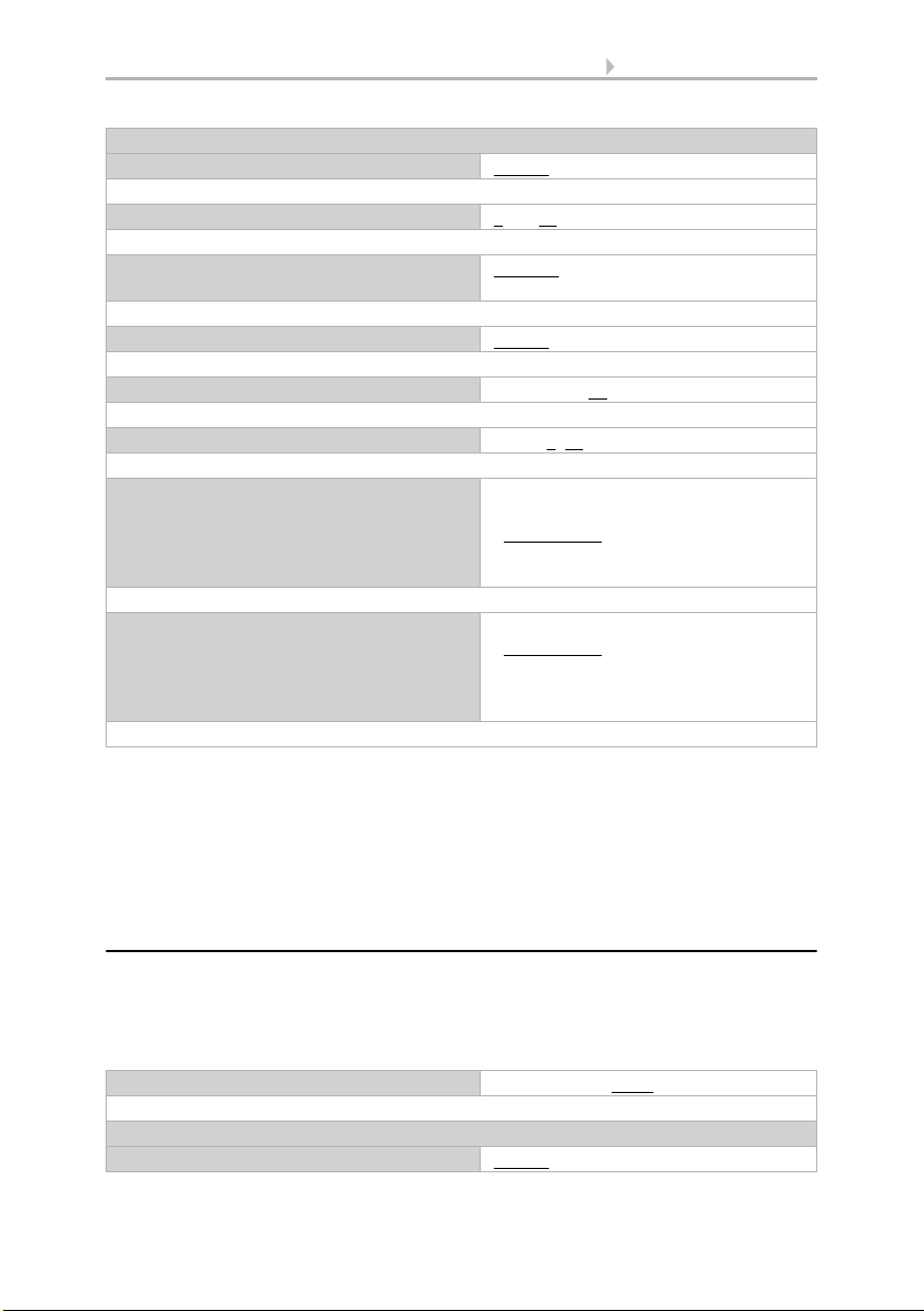
The total number KNX Bus Resets, Device Startups and Short Circuits of can be read
out by CO no.36. The counters for KNX Bus Resets and Device Startups can be read out
by COs no.17 and no.20. For example: When there was no reset or startup and CO
no.36 sends an info telegram on the bus to report an event, this event was a short cir-
cuit.
Table 3: Event Counter Readout by Communication Objects
CO Counter Read-
out
KNX Bus Resets Device Startups Short Circuits
CO no.36 "Power
supply on"
XXX
CO no.17 "Number
of restarts"
X
CO no.20 "Number
of startups"
X
Reset by button press
Reset by object
Mains power outage
ETS programming
Short circuits

10 Transfer protocol
Intelligent Power Supply KNX PS640-IP 2U • Version: 21.09.2021 • Technical changes and errors excepted.
5. Transfer protocol
5.1. List of all communication objects
Abbreviations:
R Read
WWrite
C Communication
T Transmit
UUpdate
DPT Data Point Type
No. Name Function Description Lenght DPT Flags
0 Output
voltage
Send
measured
value
„With „“Cyclic sending““
the device sends the
measured output voltage
value in V (or mV).“
2 bytes
4 bytes
DPT9,
DPT14
CR-T-
1 Output
voltage
threshold
Send
alarm
status
With the measured value
entering the threshold
range a telegram with value
0 or 1 is sent. After
returning to normal
operating a telegram with
value 0 or 1 is sent.
1 bit CR-T-
2 Output
current
Send
measured
value
„With „“Sending
difference““ and „“Cyclic
sending““ the device sends
the measured output
current value in A (or mA).“
2 bytes
4 bytes
DPT7,
DPT9,
DPT14
CR-T-
3 Output
current
threshold
Send
alarm
status
With the measured value
entering the threshold
range a telegram with value
0 or 1 is sent. After
returning to normal
operating and passing
hysteresis a telegram with
value 0 or 1 is sent.
1 bit CR-T-
4 Output
current
maximu
m
Send
measured
value
„After the expired tracking
period with „“Automatic
sending““ the device sends
the measured output
current value in A (or mA).“
2 bytes
4 bytes
DPT7,
DPT9,
DPT14
CR-T-
5Temperat
ure
Send
measured
value
„With „“Sending
difference““ and „“Cyclic
sending““ the device sends
the measured temperature
value in °C.“
2 bytes CR-T-

11 Transfer protocol
Intelligent Power Supply KNX PS640-IP 2U • Version: 21.09.2021 • Technical changes and errors excepted.
6Temperat
ure
threshold
Send
alarm
status
With the measured value
entering the threshold
range a telegram with value
0 or 1 is sent. After
returning to normal
operating and passing
hysteresis a telegram with
value 0 or 1 is sent.
1 bit CR-T-
7Temperat
ure
maximu
m
Send
measured
value
„After the expired tracking
period with „“Automatic
sending““ the device sends
the measured temperature
value in °C.“
2 bytes CR-T-
10 Telegram
traffic
Send
measured
value
„With „“Sending
difference““ and „“Cyclic
sending““ the device sends
the measured bus load
value in %.“
1 byte CR-T-
11 Telegram
traffic
threshold
Send
alarm
status
With the measured value
entering the threshold
range a telegram with value
0 or 1 is sent. After
returning to normal
operating and passing
hysteresis a telegram with
value 0 or 1 is sent.
1 bit CR-T-
12 Overload
number
Send
counter
value
„With „“Sending
difference““ and „“Cyclic
sending““ the device sends
the number counter value
of overloads.“
2 bytes CR-T-
13 Overload
duration
Send
counter
value
„With „“Sending
difference““ the device
sends the time counter
value of overloads in s.“
4 bytes CR-T-
14 Short
circuit
number
Send
counter
value
„With „“Sending
difference““ and „“Cyclic
sending““ the device sends
the number counter value
of short circuits.“
2 bytes CR-T-
15 Load
detached
duration
Send
counter
value
When activated, the device
sends the time counter
value of load detachments
(due to short circuit, device
startup and KNX bus reset).
4 bytes CR-T-
No. Name Function Description Lenght DPT Flags

12 Transfer protocol
Intelligent Power Supply KNX PS640-IP 2U • Version: 21.09.2021 • Technical changes and errors excepted.
16 KNX bus
reset
Initialize Triggered by a telegram
with value 0 or 1, the device
starts a reset process.
1 bit C-WTU
17 KNX bus
reset
number
Send
counter
value
„With „“Cyclic sending““
the device sends the
number counter value of
KNX bus resets.“
2 bytes CR-T-
18 Total
operating
time
Send
counter
value
„With „“Sending
difference““ the device
sends the time counter
value of the total operating
time in s.“
4 bytes CR-T-
19 Operatin
g time
since
startup
Send
counter
value
„With „“Sending
difference““ the device
sends the time counter
value of the time elapsed
since last device startup in
s.“
4 bytes CR-T-
20 Startup
number
Send
counter
value
„With „“Cyclic sending““
the device sends the
number counter value of
device startups.“
2 bytes CR-T-
21 Duration
1
Send
counter
value
„With „“Sending
difference““ the device
sends the time counter
value (in s) of a pre-selected
variable (output current,
output voltage,
temperature) being in the
threshold range.“
4 bytes CR-T-
22 Counter 1 Send
counter
value
„With „“Sending
difference““ and „“Cyclic
sending““ the device sends
the number counter value
(in s) indicating the number
of threshold events (for
output current, output
voltage, temperature).“
2 bytes CR-T-
23 Threshol
d 1
Send
alarm
status
With the measured value
entering the threshold
range a telegram with value
0 or 1 is sent. After
returning to normal
operating and passing
hysteresis a telegram with
value 0 or 1 is sent.
1 bit CR-T-
No. Name Function Description Lenght DPT Flags

13 Transfer protocol
Intelligent Power Supply KNX PS640-IP 2U • Version: 21.09.2021 • Technical changes and errors excepted.
24 Duration
2
Send
counter
value
„With „“Sending
difference““ the device
sends the time counter
value (in s) of a pre-selected
variable (output current,
output voltage,
temperature) being in the
threshold range.“
4 bytes CR-T-
25 Counter 2 Send
counter
value
„With „“Sending
difference““ and „“Cyclic
sending““ the device sends
the number counter value
(in s) indicating the number
of threshold events (for
output current, output
voltage, temperature).“
2 bytes CR-T-
26 Threshol
d 2
Send
alarm
status
With the measured value
entering the threshold
range a telegram with value
0 or 1 is sent. After
returning to normal
operating and passing
hysteresis a telegram with
value 0 or 1 is sent.
1 bit CR-T-
27 Duration
3
Send
counter
value
„With „“Sending
difference““ the device
sends the time counter
value (in s) of a pre-selected
variable (output current,
output voltage,
temperature) being in the
threshold range.“
4 bytes CR-T-
28 Counter 3 Send
counter
value
„With „“Sending
difference““ and „“Cyclic
sending““ the device sends
the number counter value
(in s) indicating the number
of threshold events (for
output current, output
voltage, temperature).“
2 bytes CR-T-
29 Threshol
d 3
Send
alarm
status
With the measured value
entering the threshold
range a telegram with value
0 or 1 is sent. After
returning to normal
operating and passing
hysteresis a telegram with
value 0 or 1 is sent.
1 bit CR-T-
No. Name Function Description Lenght DPT Flags

14 Transfer protocol
Intelligent Power Supply KNX PS640-IP 2U • Version: 21.09.2021 • Technical changes and errors excepted.
30 Duration
4
Send
counter
value
„With „“Sending
difference““ the device
sends the time counter
value (in s) of a pre-selected
variable (output current,
output voltage,
temperature) being in the
threshold range.“
4 bytes CR-T-
31 Counter 4 Send
counter
value
„With „“Sending
difference““ and „“Cyclic
sending““ the device sends
the number counter value
(in s) indicating the number
of threshold events (for
output current, output
voltage, temperature).“
2 bytes CR-T-
32 Threshol
d 4
Send
alarm
status
With the measured value
entering the threshold
range a telegram with value
0 or 1 is sent. After
returning to normal
operating and passing
hysteresis a telegram with
value 0 or 1 is sent.
1 bit CR-T-
33 Counter
reset
Reset all All number counter values
and duration counter values
(except total operating time
and device startup number)
are set to zero by a telegram
with “1”.
1 bit C-WT-
34 Measure
d values
Send all Measured values of output
current, output voltage and
temperature are sent as
response to a “1” telegram.
1 bit C-WT-
No. Name Function Description Lenght DPT Flags

15 Transfer protocol
Intelligent Power Supply KNX PS640-IP 2U • Version: 21.09.2021 • Technical changes and errors excepted.
35 Counter
values
Send all Event counter values
(overload number, overload
duration, load detached
duration, total operating
time, operating time since
last device startup, Duration
1-4, Counter 1-4) are sent as
response to a “1” telegram.
1 bit C-WT-
36 Power
supply is
on
Send info
value 1
After device startup and
after recovery from output
failure, a “1” telegram to
announce that the device is
on the bus is sent
(according to the pre-set
delay).
1 bit CR-T-
37 Heartbea
t
Send info
value 1
According to the pre-set
heartbeat period, an info
telegram with value 1 is
sent regularly on the bus
indicating the power supply
is on.
No. Name Function Description Lenght DPT Flags

16 ETS Database Parameters
Intelligent Power Supply KNX PS640-IP 2U • Version: 21.09.2021 • Technical changes and errors excepted.
6. ETS Database Parameters
The default settings of the parameter are labelled by an underscore.
6.1. General
The "General" tab contains the parameters related to the presence message sending
and the KNX bus reset that can be initialized by communication object no.16. With use
of the communication object no.37 "Heartbeat" the device periodically sends out a
telegram with "1". With use of the communication object no.36 "Power supply is on"
the device sends out a telegram with "1" after a KNX bus reset, a device startup and a
short circuit. After returning to normal working condition during the time delay no
telegrams are sent. Then, the "Power supply is on" telegram is the first one that is sent.
6.2. Measurements
The "Measurements" tab contains the menus "Output voltage", "Output current" and
"Device temperature". The excess threshold range of the "Output voltage" is fixed and
located outside the working range (28-31V). For example, with no "Output voltage"
hysteresis the "Behaviour on alarm deactivation" function is executed on just entering
the working range. The "Output current" and the "Device temperature" excess
threshold ranges both are located above the working range.
Heartbeat period [s] 10…32,000 s; 60 s
Info telegram (with "1") is regularly sent after this time period.
Induce a KNX bus reset with 0 • with 1 • with 0 and 1
Set type of telegram to trigger (remotely) a KNX bus reset.
Delay time for "Power supply on" (obj. 36) disabled • 1 min • 2 min…5 min •
10 min • 15 min…30 min • 1 h • 2 h…8 h
When returning to normal operation, after this time delay, the info telegram (containing
"1") is sent by CO no.36.
Output voltage
Output voltage [V] disable • enable
Enable/disable group associations, measurement and following settings.
Object type 2-byte (DPT9) • 4-byte (DPT14)
Select datapoint type.
Cyclic sending disabled • 1 min • 2 min…5 min •
10 min • 15 min…30 min • 1 h • 2 h…8 h
Info telegram is sent regularly.
Threshold alarm disable • enable
Enable/disable the alarm function.
17 ETS Database Parameters
Intelligent Power Supply KNX PS640-IP 2U • Version: 21.09.2021 • Technical changes and errors excepted.
Behaviour on alarm activation • disabled
• send value 0
• send value 1
• set value to 0
• set value to 1
Leaving the working range.
Behaviour on alarm deactivation • disabled
• send value 0
• send value 1
• set value to 0
• set value to 1
Entering the working range.
Output current
Output current [mA] disable • enable
Enable/disable group associations, measurement and following settings.
Object type • 2-byte (DPT7, integer)
• 2-byte (DPT9, float)
• 4-byte (DPT14)
Select datapoint type.
Sending difference disabled • 5 mA • 10 mA..25 mA • 50 mA
Difference between actual and last sent value which triggers the sending.
Cyclic sending disabled • 1 min • 2 min…5 min •
10 min • 15 min…30 min • 1 h • 2 h…8 h
Info telegram is sent regularly.
Threshold alarm disable • enable
Enable/disable the alarm function.
Threshold 0…800 [mA]; 640
Select threshold value to execute the "Behaviour on alarm activation".
Hysteresis 0…640 [mA]; 1
Select hysteresis interval value to execute the "Behaviour on alarm deactivation".
Behaviour on alarm activation • disabled
• send value 0
• send value 1
• set value to 0
• set value to 1
Select action on entering the threshold range.
Behaviour on alarm deactivation • disabled
• send value 0
• send value 1
• set value to 0
• set value to 1
Select action on leaving the threshold (+hysteresis) range.
18 ETS Database Parameters
Intelligent Power Supply KNX PS640-IP 2U • Version: 21.09.2021 • Technical changes and errors excepted.
• Using the "Sending difference" function with the "Output voltage" is possible
only within the "Alarm 1,2,3,4" tabs like described in chapter 3.7.
• The "Output voltage" value is valid only if most of the load is on the KNX bus
output
• If the "Output current" value is < 10 mA, for calculations, the input voltage is
assumed to be at 230 V AC
6.3. Maximum Tracking
With setting the "Tracking period" a certain period of time is tracked in order to find the
maximum observed value contained. After each expired period this value can be sent
over the bus. The maximum tracking function is available for the measurement
sources "Output current" and "Device Temperature".
Device temperature
Device temperature [°C] disable • enable
Enable/disable group associations, measurement and following settings.
Sending difference 2...10 °C
Difference between actual and last sent value which triggers the sending.
Cyclic sending disabled • 1 min • 2 min…5 min •
10 min • 15 min…30 min • 1 h • 2 h…8 h
Info telegram is sent regularly.
Alarm settings disable • enable
Enable/disable the alarm function.
Threshold 0…110 [°C]; 70
Select threshold value to execute the "Behaviour on alarm activation".
Hysteresis 0…40; 1 [°C]
Select hysteresis interval value to execute the "Behaviour on alarm deactivation".
Behaviour on alarm activation • disabled
• send value 0
• send value 1
• set value to 0
• set value to 1
Select action on entering the threshold range.
Behaviour on alarm deactivation • disabled
• send value 0
• send value 1
• set value to 0
• set value to 1
Select action on leaving the threshold (+hysteresis) range.
Tracking period [s] 10…32,000 [s]; 1,800
Determination of the time period for maximum value tracking.
Maximum value of Output current
Output current maximum [mA] disable • enable
Other manuals for KNX PS640-IP 2U
2
This manual suits for next models
1
Table of contents
Other elsner elektronik Power Supply manuals

elsner elektronik
elsner elektronik KNX PS640 User manual

elsner elektronik
elsner elektronik KNX PS640+ Guide

elsner elektronik
elsner elektronik KNX PS640+ User manual

elsner elektronik
elsner elektronik KNX PS640 Instruction manual

elsner elektronik
elsner elektronik KNX PS640 4U User manual

elsner elektronik
elsner elektronik KNX PS640+ Guide

elsner elektronik
elsner elektronik KNX PS640-IP 2U User manual

elsner elektronik
elsner elektronik KNX PS640-IP 2U User manual


