elsner elektronik KNX PS640+ Guide

Power Supply System
KNX PS640+
with bus functions
Installation and Adjustment
Elsner Elektronik GmbH Steuerungs- und Automatisierungstechnik
Herdweg 7 • D-75391 Gechingen • Deutschland
Phone.: +49 (0) 70 56/93 97-0 • Fax: +49 (0) 70 56/93 97-20

2
Contents
Product description.......................................................................................................3
Technical data ...................................................................................................................................... 3
Installation and Commissioning....................................................................................4
Installation............................................................................................................................................ 5
Settings of the device ...................................................................................................6
Starting position .................................................................................................................................. 6
Line reset .............................................................................................................................................. 6
Data memory ....................................................................................................................................... 7
Operating data ..................................................................................................................................... 8
Language.............................................................................................................................................. 8
Transmission protocol...................................................................................................9
Abbreviations....................................................................................................................................... 9
Listing of all communication objects................................................................................................. 9
Setting of parameters (Software ETS).........................................................................10
General settings................................................................................................................................. 10
Messages............................................................................................................................................ 12
Current threshold value .................................................................................................................... 14
KNX PS640+ from software version 1.01, ETS programme version 1.1
Version: 26/08/2009. Errors excepted. Subject to technical changes.

3
Product description
The Power Supply System KNX PS640 delivers a 29 V bus voltage for the KNX system
and 24 V DC supply voltage for 24 V devices. Special operating conditions such as short
circuit, electrical surge, overcharge or excess temperature are recorded and may be
read off on the display. The present power discharge is displayed as well. It is possible
to reset the connected bus devices directly by means of the key pad.
In addition all functions can be realised via the bus, too, e. g. the transfer of malfunction
messages and operating data and a time/period reset. Malfunction messages are stored
by the KNX PS640+.
Functions:
•Delivers a 29 V KNX bus voltage (reduced), output current max. 640 mA, short-
circuit proof
•Delivers 24 V DC (not reduced), output current max. 150 mA
•Reset of a line directly on the device
•Record of operating hours, overload, external overvoltage, internal overvoltage,
short circuit and excess temperature
•Display of operating data bus voltage, bus current and temperature of the device
•The display may be shown in German, English, Spanish or Dutch
•Bus connection for data transfer (e. g. malfunction messages, operating data)
•Possibility for reset and diagnostics via the bus
The programme file for KNX software ETS (format VD2) is ready for download on the
Elsner Elektronik website at www.elsner-elektronik.de in the “Service” menu.
Technical data
Housing: Plastic material
Colour: White
Mounting: Snap-on fitting on mounting rails
Protection category: IP 20
Dimensions: approx. 123 x 89 x 61 (W x H x D, mm), 7 width units
Weight: approx. 370 g
Ambient temperature: Operation -5…+45 °C, storage -25…+70°C
Ambient air humidity: max. 95% RH, avoid bedewing
Operating voltage: 230 V AC , 50 Hz
Outputs: • KNX bus voltage 29 V (reduced),
Output current max. 640 mA, short-circuit proof
• 24 V DC (not reduced), Output current max. 150 mA
• KNX data
Data output: KNX +/- bus terminal plug
BCU type: Own micro controller

4
PEI type: 0
Group addresses: max. 200
Allocations: max. 200
Communication objects: 27
The following standards have been considered for the evaluation of the product in
terms of electro magnetic compatibility:
Transient emissions:
•EN 60730-1:2000 Section EMV (23, 26, H23, H26) (threshold category: B)
•EN 50090-2-2:1996-11 + A1:2002-01 (threshold category: B)
•EN 61000-6-3:2001 (threshold category: B)
Interference resistance:
•EN 60730-1:2000 Section EMV (23, 26, H23, H26)
•EN 50090-2-2:1996-11 + A1:2002-01
•EN 61000-6-1:2004
The product has been tested for the above mentioned standards by an accredited EMV
laboratory.
Installation and Commissioning
Attention! Mains voltage! The legal national regulations
must be complied with.
Installation, inspection, commissioning and troubleshooting of the power supply
system must only be carried out by a competent electrician. Disconnect all lines to be
assembled, and take safety precautions against accidental switch-on.
The power supply is exclusively intended for appropriate use. With each inappropriate
change or non-observance of the instructions for use, any warranty or guarantee claim
will be void.
After unpacking the device, check immediately for any mechanical damages. In case of
transport damage, this must immediately notified to the supplier.
If damaged, the power supply system must not be put
into operation.
If an operation without risk may supposedly not be guaranteed, the plant must be put
out of operation and be secured against accidental operation.
The power supply system must only be operated as stationary system, i.e. only in a
fitted state and after completion of all installation and start-up works, and only in the
environment intended for this purpose.
Elsner Elektronik does not assume any liability for changes in standards after
publication of this instruction manual.

5
Installation
Observe the correct installation. Incorrect installation may destroy the power supply
system or connected electronic devices.
Housing
1 Bus voltage power
OUT (KNX terminal + / -)
2 Programming LED and
programming bushbutton
3 Bus data (KNX terminal
+ / -), connection for line
or main line or sector
4 Input operating voltage
230 V AC, L / N / PE
5 Output direct current
voltage 24 V DC, + / -
Connections 4 and 5 are
suitable for solid conductors
up to 1.5 mm² or conductors
with fine wires
Scheme
Auxiliary supply 24 V DC
(max. 150 mA)

6
Settings of the device
Starting position
The following may be read off and set on the display of the Power Supply System KNX
PS640+:
•Reset of a line
•Recall of the data memory with operating hours, overcharge, external electrical
surge, internal electrical surge, short circuit and excess temperature
•Recall of the operating data bus voltage, bus current and temperature
•Language of display
The display is dimmed after 60 seconds if during this period no key is pressed.
Line reset
In starting position, press key once.
Press key once more in order to get into the sector
“Line reset”.
Move the cursor (flashing rectangle at right edge) to
the desired setting with the keys or and confirm
with key .
Yes: Reset is activated. The line is switched to neutral and shorted. The
basic setting displays: “Reset is active!”
No: Reset not activated. The power supply system works in normal
operation.
30 seconds: A reset of 30 seconds is started. Afterwards, the line is supplied
with voltage as usual. During the reset state, which lasts 30
seconds, the basic setting displays: “Reset active: XX sec”
(countdown).
With key , you return to the previous menu level.
el
sner e
l
e
kt
ron
ik
KNX Power Supply
Normal Operation
Diagnostics >
el
sner e
l
e
kt
ron
ik
KNX Power Supply
Normal Operation
Diagnostics >
Li
ne
R
e
se
t
>
™
Data Memory >
Operating Data >
Language
R
ese
t
:
Y
es
™
No
30 seconds
Reset not active!

7
Data memory
In starting position, press key once.
Move the cursor (flashing rectangle at right edge) to
the “Data memory” menu with the keys and and
confirm with key .
Move the cursor to the desired menu with the up and down keys and press key .
Operating Hours
The operating hours of the power supply system are
displayed in years, days and hours.
With key you return to the previous menu level.
Overload
The number of overload incidents and the total time in
days, hours and minutes are displayed.
With key you return to the previous menu level.
External Overvoltage
The number of external overvoltage incidents is
displayed.
With key you return to the previous menu level.
Internal Overvoltage
The number of internal overvoltage incidents is
displayed.
With key you return to the previous menu level.
Sh
or
t
c
i
rcu
it
>
Excess Temperat. >
H
ours o
fO
pera
ti
on
>
™
Overload >
Ext. Overvoltage >
Int. Overvoltage >
R
un
ti
me:
0
year
s
0 day 0 hrs.
< = Back
O
ver
l
oa
d
d
e
t
ec
t
e
d
0 times. Duration:
0 day. 0 hrs. 0 min
< = Back
E
x
t
erna
l
O
vervo
lt
age
was detected
0 times.
< = Back
I
n
t
erna
l
O
vervo
lt
age
was detected
0 times.
< = Back
Li
ne
R
e
se
t
>
Data Memory > ™
Operating Data >
Language >
el
sner e
l
e
kt
ron
ik
KNX Power Supply
Normal Operation
Diagnostics >

8
Short Circuit
The number of short circuit incidents at the bus is
displayed.
With key you return to the previous menu level.
Excess Temperature
The number of excess temperature incidents on the
circuit board of the device is displayed.
With key you return to the previous menu level.
Operating data
In starting position, press key once.
Move the cursor (flashing rectangle at right edge) to
the “Operating Data” menu with the keys and and
confirm with key .
The current values of
•Bus voltage
•Bus current
•Temperature on the circuit board of the device
•are displayed.
With key you return to the previous menu level.
Language
In starting position, press key once.
Move the cursor (flashing rectangle at right edge) to
the “Language” menu with the keys and and
confirm with the key .
B
us
V
olt
age
29
.
4
V
Bus Current 320 mA
Temperature 42.1°C
A
s
h
or
t
at
th
e
b
us
was detected
0 times.
< = Back
E
xcess
T
e
mpera
t
ure
on the board
was detected
0 times!
Li
ne
R
e
se
t
>
Data Memory >
Operating Data > ™
Language >
L
i
ne
R
e
se
t
>
Data Memory >
Operating Data >
Language > ™
el
sner e
l
e
kt
ron
ik
KNX Power Supply
Normal Operation
Diagnostics >
el
sner e
l
e
kt
ron
ik
KNX Power Supply
Normal Operation
Diagnostics >

9
Move the cursor to the desired language with the up
and down keys and press the key . The display
automatically jumps to the previous menu in the
desired language.
With key you get back by one menu level to the basic setting.
Transmission protocol
Abbreviations
Flags:
C Communication
R Read
W Write
T Transmit
U Update
Listing of all communication objects
No. Name Function EIS type Flags
0 Bus voltage [V] Output 14.030 C R T
1 Bus current [mA] Output 9.021 C R T
2 Permanent reset (1 = active | 0 = inactive) Input 1.003 C R W
3 Time reset
(1 = 30 seconds active | 0 = inactive)
Input 1.003 C R W
4 Reset status of the line
(1 = active | 0 = inactive)
Output 1.002 C R T
5 Overload (0 = normal | 1 = overload) Output 1.002 C R T
6 external overvoltage
(0 = normal | 1 = overvoltage)
Output 1.002 C R T
7 internal overvoltage
(0 = normal | 1 = overvoltage)
Output 1.002 C R T
8 Short circuit
(0 = normal | 1 = short circuit)
Output 1.002 C R T
9 Overtemperature
(0 = normal | 1 = overtemperature)
Output 1.002 C R T
10 System defect
(0 = normal | 1 = defect)
Output 1.002 C R T
11 1 bit malfunction collection
(operation = 0 | fault = 1)
Output 1.002 C R T
12 8 bit status collection Output 5.010 C R T
13 Date Input 11.001 C R W
14 Time Input 10.001 C R W
S
prac
h
e :
D
eu
t
sc
h
™
Language :English
Idioma :Espanol
Taal :Hollands

10
No. Name Function EIS type Flags
15 Recall error information
(1 = No.+1 | 0 = No.-1)
Input 1.008 C R W
16 Message part 1 Output 16.000 C R T
17 Message part 2 Output 16.000 C R T
18 Message part 3 Output 16.000 C R T
19 Message part 4 Output 16.000 C R T
20 Threshold value: 16 bit value [mA] Input / Output 9.021 C R W T U
21 Threshold value:
1 = Increment | 0 = Decrement
Input 1.008 C R W
22 Threshold value: Increment Input 1.017 C R W
23 Threshold value: Decrement Input 1.017 C R W
24 Threshold value: Switching output Output 1.002 C R T
25 Threshold value: Switching output block Input 1.003 C R W
26 Software version readable 217.001 C R
Setting of parameters (Software ETS)
General settings

11
Measured values:
……………………………
Transmission behaviour object “bus voltage” • do not send
• send cyclically
• send in case of change
• send in case of change and cyclically
Sending cycle
(only if sending “cyclically”)
5 sec • 10 sec • 30 sec • 1 min • … • 2 h
Change in %
(only if sending “in case of change”)
1 … 50
Transmission behaviour object “bus current” • do not send
• send cyclically
• send in case of change
• send in case of change and cyclically
Sending cycle
(only if sending “cyclically”)
5 sec • 10 sec • 30 sec • 1 min • … • 2 h
Change in %
(only if sending “in case of change”)
1 … 100
Reset of the linie:
……………………………
What shall be used for the reset?
display and keyboard Yes
object “permanent reset”
1 = reset | 0 = no reset
No • Yes
object “time reset”
1 = 30 seconds reset | 0 = no reset
No • Yes
Use object “reset status of the line” No • Yes
Other:
……………………………
Maximum telegram quota 1 • 2 • 3 • 5 • 10 • 20 Telegrams per second
General sending delay after
power up and programming
5 sec • 10 sec • 30 sec • 1 min • … • 2 h
12
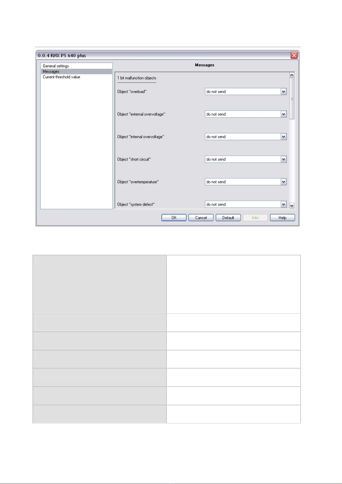
Messages
1 bit malfunction objects:
……………………………
Object “overload” • do not send
• send in case of change
• send in case of change to 1
• send in case of change to 0
• send in case of change and cyclically
• send in case of change to 1 and cyclically
• send in case of change to 0 and cyclically
Sending cycle
(only if sending “cyclically”)
5 sec • 10 sec • 30 sec • 1 min • … • 2 h
Object “external overvoltage” [The setting options are similar to object
“overload”]
Object “internal overvoltage” [The setting options are similar to object
“overload”]
Object “short circuit” [The setting options are similar to object
“overload”]
Object “overtemperature” [The setting options are similar to object
“overload”]
Object “system defect” [The setting options are similar to object
“overload”]

13
1 bit malfunction collection:
……………………………
Object “1 bit malfunction collection”
This object results in a
disjunction of the 1 bit malfunction objects
• do not send
• send in case of change
• send in case of change to 1
• send in case of change to 0
• send in case of change and cyclically
• send in case of change to 1 and cyclically
• send in case of change to 0 and cyclically
Sending cycle
(only if sending “cyclically”)
5 sec • 10 sec • 30 sec • 1 min • … • 2 h
8 bit status collection:
……………………………
Object “8 bit status collection” • do not send
• send in case of change
• send in case of change and cyclically
Sending cycle
(only if sending “cyclically”)
5 sec • 10 sec • 30 sec • 1 min • … • 2 h
Bit 0 = reset status of the linie
Bit 1 = overload
Bit 2 = external overvoltage
Bit 3 = internal overvoltage
Bit 4 = short circuit
Bit 5 = overtemperature
Bit 6 = current threshold value exceeded
Bit 7 = system defect
Error log:
……………………………
Use error log No • Yes
If the error log ist used:
Object “message part 1” sends signal:
Error no. (1 = latest error)
Object “message part 2” sends signal:
Error type
Object “message part 3” sends signal:
Date of error start
Object “message part 4” sends signal:
Time of error start

14
Current threshold value
Use threshold value No • Yes
If the threshold value ist used:
Threshold value:
……………………………
If the threshold value is set by parameter:
Threshold value is set by Parameter
Threshold value in mA 0 … 640
Hysteresis of the threshold value in % 0 … 50
If the threshold value is set by communication object:
Threshold value is set by Communication object
The value communicated last shall be
maintained
• not
• after restoration of voltage
• after restoration of voltage and
programming (Do not use for first
commissioning)
Start threshold value in mA
valid until 1. communication
(only if the value communicated last is “not”
maintained or “after restoration of voltage”)
0 … 640

15
Type of threshold change • Absolute value with a 16 bit com.object
• Increment/decrement with one comm. object
• Increment/decrement with two comm.
objects
Step size in mA
(only with “increment/decrement”)
1 • 2 • 5 • 10 • 20 • 50 • 100
Hysteresis of the threshold value in % 0 … 50
Switching output:
……………………………
Output is at
(TV = Threshold value)
• TV above = 1 | TV – hyst. below = 0
• TV above = 0 | TV – hyst. below = 1
• TV below = 1 | TV + hyst. above = 0
• TV below = 0 | TV + hyst. above = 1
Switching delay from 0 to 1 none • 1 s • 2 s • 5 s • 10 s • … • 2 h
Switching delay from 1 to 0 none • 1 s • 2 s • 5 s • 10 s • … • 2 h
Switching output sends • send in case of change
• send in case of change to 1
• send in case of change to 0
• send in case of change and cyclically
• send in case of change to 1 and cyclically
• send in case of change to 0 and cyclically
Send switching output in a cycle of
(only if sending “cyclically”)
5 sec • 10 sec • 30 sec • 1 min • … • 2 h
Blocking:
……………………………
Use block of the switching output No • Yes
If the block of the switching output is used:
Use block of the switching output Yes
Evaluation of the blocking object • if value 1: block | if value 0: release
• if value 0: block | if value 1: release
Value of the blocking object
before 1. communication
0 • 1
Bahaviour of switching output
with blocking • do not send telegram
• send 0
• send 1

16
The behaviour with release of the switching output depends on the value of the
parameter “Switching output sends …” (see ”Switching output”)
Value of parameter
“Switching output sends”:
Setting options “Behaviour of the switching
output with release”:
in case of change • do not send telegram
• send status of the switching output
in case of change to 1 • do not send telegram
• if switching output = 1 !send 1
in case of change to 0 • do not send telegram
• if switching output = 0 !send 0
in case of change and cyclically send status of the switching output
(no selection)
in case of change to 1 and cyclically if switching output = 1 !send 1
(no selection)
in case of change to 0 and cyclically if switching output = 0 !send 0
(no selection)
Other manuals for KNX PS640+
2
Table of contents
Other elsner elektronik Power Supply manuals

elsner elektronik
elsner elektronik KNX PS640+ Guide

elsner elektronik
elsner elektronik KNX PS640 Instruction manual

elsner elektronik
elsner elektronik KNX PS640 User manual

elsner elektronik
elsner elektronik KNX PS640-IP 2U User manual

elsner elektronik
elsner elektronik KNX PS640 4U User manual

elsner elektronik
elsner elektronik KNX PS640-IP 2U Guide

elsner elektronik
elsner elektronik KNX PS640-IP 2U User manual

elsner elektronik
elsner elektronik KNX PS640+ User manual


