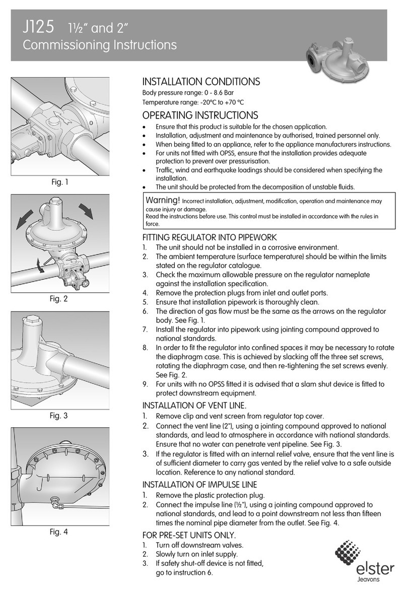
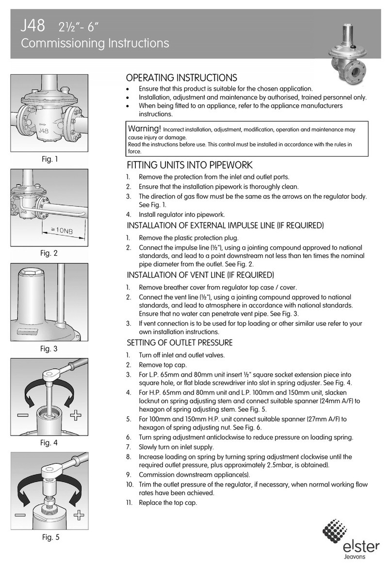
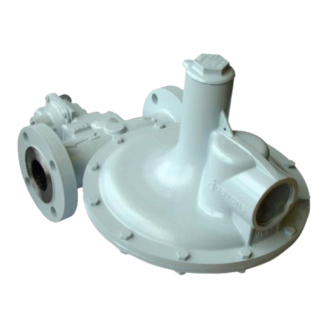
Elster SR113 User manual

Instruction Manual
SR100 Series Service Regulators

SR100 Series Service Regulators
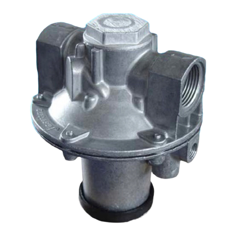
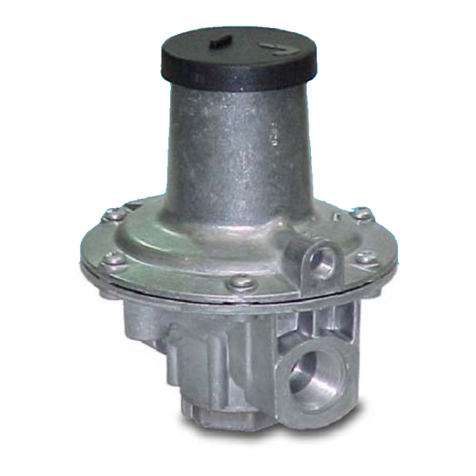
The SR113 Service Regulator comes
equipped with a full capacity internal
relief valve and features a 3/4" or 1" NPT
threaded vent.
Available 180° valve body sizes: 3/4" x
3/4", 3/4" x 1" and 1" x 1" NPT or BSP-TR.
Available 90° valve body sizes: 3/4" x 3/4",
3/4" x 1" and 1" x 1" NPT or BSP -TR.
Offset valve body sizes: 3/4" x 3/4", 3/4" x 1"
and 1" x 1" NPT or BSP-TR.
Applications
Do not connect the inlet of the
regulator to a pressure source
higher than recommended
in Table 3 on page 4. Never
connect the regulator outlet to
the pressure source. Observe
the flow direction arrow on the
valve body. Some additional
form of overpressure protection
may be required In applications
where downstream maximum
pressure ratings are less than
the regulator inlet pressure
Install, operate, inspect and
maintain the regulators as
outlined in the following
instructions and in accordance
with your company's policies
and applicable federal,
state, and local codes and
laws. Failure to follow these
instructions may result in
damage to the regulator or
personal injury.
Check installation location for1.
suitability. Physical changes may
have been made to the building site
since the original installation.
Examine regulator for shipping damage.2.
Check regulator and piping for foreign3.
matter which may have accumulated
during shipment or handling.
To prevent regulator damage
and possible personal injury,
pressures must not exceed:
Maximum inlet pressure,
normal service (P1): Depending
on orifice size, up to 125 PSIG
(see Table 3 on page 4).
Maximum outlet pressure,
normal service (P2): Depending
on spring selection, up to 2
PSIG (see Table 1 on page 3).
Maximum inlet pressure for
abnormal or emergency service
without causing damage to
regulator case is 175 PSIG.
Maximum outlet pressure which
can be contained by pressure
carrying components (no flange
leakage to atmosphere except
for normal relief action) is 10
PSIG. Remove from service if
regulator is subjected to this
condition.
Maximum outlet pressure
for abnormal service without
damage to internal components
is 50 PSIG. Remove from service
if regulator is subjected to this
condition.
General Information
G
Regulator Pressure Ratings
!WARNING
Preparations
!WARNING
SR100 Series Service Regulators 02 Elster American Meter
Check regulator information stamped4.
on seal plug to determine if regulator is
suitable for intended service (see Item
14, page 3).
Suitable stop valve(s) should be5.
installed and conveniently located.
Filters are available from Elster6.
American Meter for applications
where pipeline contaminants are
believed to be present.
Regulators may be used at7.
temperatures between -20°F and
+150°F (-30°C and +65°C).
Model Number Description
SR113 Basic regulator, full-capacity internal relief with 3/4"
or 1" NPT vent.

1
2
3
4
5
6
7
8
9
10
11
12 13
14
15
16
17
18
19
20
21
22
Figure 1
23
Model
Orifice Size
Spring Range
Date Code
Yr/Wk Mfg.
Disc, Valve Seat
Seal Ring, Valve Body
Diaphragm
Screw, Diaphragm Case
Bolt, Valve Body
Spring, Pressure (Table 1)
Valve, Orifice (Table 2)
Diaphragm Case
Screw, Pressure Adjustment
Stem, Relief Valve
Retainer, Relief Valve Spring
Lever
Pin, Lever
Plug, Seal
Spring, Relief Valve
Guide, Valve Plunger
Plunger, Valve
Assembly, Top
Valve, Body
Plate, Diaphragm
Screen, Vent
Gasket, Seal Plug
Nut, Valve Body
7
1
2
3
4
5
6
7
8
9
10
11
12
13
14
15
16
17
18
19
20
21
22
23
Pressure Spring
Table 1
Table 2
Orifice
SR100 Series Service Regulators 03 Elster American Meter
Outlet
Pressure
Color
Code
Part
Number
6" to 8" W.C. Blue/Yellow 70017P138
7" to 12" W.C. Blue/Red 70017P139
13" to 16" W.C. Blue/White 70017P140
21" to 35 W.C. Blue/Orange 70017P141
2 PSIG White 70017P060
Orifice Size
Standard
Part Number
5/16" 72494P022
1/4" 72494P021
3/16" 72494P020
1/8" x 3/16" 72494P030

4
Figure 2
1
2
3
5
This is the maximum inlet the regulator should operate at to insure complete lockup
at no-flow conditions.
Maximum Recommended Inlet Pressure
increase outlet pressure; counterclockwise to decrease
outlet pressure.
Establish the outlet pressure within the range limits ofg.
the pressure spring used.
To test for the regulator's ability to fully shut off (lock-up),h.
shut off all flow downstream of the regulator. At lock-up,
the outlet pressure will be somewhat higher than the set
pressure. However, if the pressure continues to rise after
3 seconds, the regulator must be repaired. Observe for
30 seconds.
When the set pressure is properly adjusted,i.
depressurize and remove gauge(s) and lines.
Replace seal plug (4).j.
Pressurize and check all connections for leaks.k.
(Numbers in parentheses refer to Figure 2.)
Remove all shipping plugs from the valve body.1.
Use good piping practice. Be sure piping and regulator are2.
free of dirt, pipe dope and other debris. Apply pipe dope to
male threads only.
Install regulator. Make certain it is installed correctly with3.
inlet pipe connected to the inlet regulator connection and
flow is in the direction as indicated by arrow located on
valve body (1). Elster American Meter suggests the vent
point downward to prevent entry of water and debris. By
removing the two valve body bolts (2), the diaphragm case
(3) may be rotated in 90-degree increments in relation to the
valve body (1). Replace and tighten the two valve body bolts
(2) to 100 ±25 in. lbs. A regulator installed within a building
should be located as near as practical to the point of service
line entrance.
Make sure inlet pressure is always less than the maximum4.
recommended inlet pressure for the orifice size (see Table
3). Turn gas on slowly. If an outlet valve is used, it should be
opened first. Do not subject the regulator to a sudden surge
of inlet pressure.
Assure that there are no leaks and all connections are tight.5.
The SR100 Series regulator is preset at the factory. Should6.
you decide to adjust the set pressure, perform the following:
Turn gas off and depressurize the system.a.
Install outlet pressure gauge.b.
Turn gas on slowly.c.
Establish a low flow rate between 45 and 55 SCFH.d.
Remove seal plug (4) with a 1" wrench.e.
Turn pressure spring adjustment screw (5) clockwise tof.
Inside Installation: A vent line of sufficient
diameter to carry gas vented by the regulator to
a safe outside location away from any opening in
the building is required. For all sizes of regulators,
a 3/4" or 1" threaded vent is provided for a vent
line. Verify vent piping does not interfere with the
vent flapper movement.
Outside Installation: Care must be taken to prevent
vent opening from freezing closed, becoming
blocked, or allowing water to enter from any
cause. Particular consideration should be given to
sites where flooding, snow, or freezing rain may
be experienced. The vent or vent line port should
point vertically downward, and overhead protection
should be used where necessary.
Installation
!WARNING
SR100 Series Service Regulators 04 Elster American Meter
Table 3
Orifice Size Inlet Pressure (PSIG)
1/8" x 3/16" 125
3/16" 125
1/4" 125
5/16" 100

4
6
Figure 3
2
3
1
5
As a knowledgeable user of Elster American
Meter Company products, you should be
aware that parts in the Company's meters
and regulators contain, or are coated with,
heavy metals such as cadmium, zinc, lead
and chromium. Repair or refurbishment
of this equipment should take into account
the presence of these materials and should
comply with all state and federal requirements
concerning worker protection, proper disposal,
and safety including protection against exposure
to dust and fumes.
SR100 Series Service Regulators 05 Elster American Meter
Inspection of Valve Seat Disc and Orifice
(Numbers in parentheses refer to Figure 3.)
Shut off gas supply and depressurize the system.1.
Remove two valve body bolts (2) securing the diaphragm2.
case (3) to the valve body (1) with a 1/2" wrench. Separate
the diaphragm case from the valve body.
Visually check the seating edge of the orifice inside the3.
valve body (1) . If it is nicked or damaged, it should be
replaced with a new orifice to provide positive shut off. See
Maintenance instructions for replacing orifice on page 6.
Inspect the surface of the valve seat disc (4). If it is scored4.
or uneven, replace it as outlined in the Maintenance
instructions for replacing the seat disc on page 5.
Install new seal ring (5) in the diaphragm case groove.5.
Inspect unit for cleanliness and proper positioning of the6.
parts. Pay particular attention to the proper positioning of
the seal ring (5) in the groove.
Install the diaphragm case (3) on the valve body (1). Make7.
sure the vent is positioned so that it cannot become plugged
or allow water to enter. Replace and tighten the two valve
body bolts (2) to 100 ±25 in. lbs.
Proceed to Steps 4, 5 and 6 of the Installation instructions.8.
Regulators are pressure-control mechanisms
having numerous moving parts which can
wear. In addition, regulator damage may occur
from external sources. For these reasons, the
regulator should be periodically inspected and
checked for proper operation. The frequency
of inspection depends on the severity of the
service conditions and the requirements of
applicable local, state, and federal codes and
regulations.
Follow the procedure below for field inspection
of the orifice and seat disc. Repair parts are
available through Elster American Meter if parts
are worn or damaged. Exercise care to prevent
foreign material from entering the regulator
during any inspection or maintenance activities.
Inspection Maintenance
!CAUTION
Replacing Seat Disc
(Numbers in parentheses refer to Figure 3.)
Follow steps 1 and 2 of the Inspection instructions on page 51.
to access seat disc.
Carefully insert the tip of a knife along the edge of the seat2.
disc (4) and the lift the seat disc out of the plunger (6).
Install a new seat disc (4) into the plunger (6) by pressing3.
into place. Make sure that the disc is pressed completely
into the plunger (6).
Proceed to Steps 5, 6, 7, and 8 of the Inspection instructions4.
on page 5.
!CAUTION

Figure 4
2
3
1
42
1
3
Figure 5
5
Regulators that have an orifice size different than
shown on the seal plug tag must have their set
pressure reestablished. Mark the new orifice size
on the regulator seal plug or on its tag.
Regulators that have a pressure spring removed
or replaced must have their set pressure
reestablished. If the pressure spring is different
from that shown on the seal plug or tag, mark
the new spring range on the regulator seal plug
or on its tag.
Replacing the Pressure Spring
(Numbers in parentheses refer to Figure 5.)
Shut off gas supply and depressurize the system.1.
Remove seal plug (1) with a 1" wrench.2.
Unscrew pressure adjusting screw (2) with a 3/8" nut driver.3.
Completely remove the pressure adjusting screw (2).
Remove the pressure spring (3). Install new pressure spring.4.
Replace the pressure adjusting screw and turn adjusting5.
screw to about mid position.
Proceed to Steps 4, 5, and 6 of the Installation instructions6.
on page 4 to set delivery pressure.
Maintenance
!CAUTION
Maintenance
!CAUTION
Replacing the Orifice
(Numbers in parentheses refer to Figure 4.)
Shut off gas supply and depressurize the system.1.
Remove the two valve body bolts (2) securing the diaphragm2.
case (3) to the valve body (1) with a 1/2" wrench. Place the
diaphragm case aside and protect the seat disc (5) from dirt
particles and physical damage.
Remove the orifice valve (4) with a 7/8" hex socket wrench.3.
Sparingly apply Henkell G30 or Loctite "Stainless Steel PST"4.
thread sealant or equivalent (not supplied) to the new orifice
threads.
Carefully start the threads of the orifice into the valve body5.
and tighten to 350 ±50 in lbs. Care must be taken to prevent
nicking the orifice.
Proceed to Steps 5, 6, 7 and 8 of the Inspection instructions6.
on page 5.
SR100 Series Service Regulators 06 Elster American Meter

SR100 Series Service Regulators 07 Elster American Meter
Table of contents
Other Elster Controllers manuals
Popular Controllers manuals by other brands

piezosystemjena
piezosystemjena 5V10 OEM quick start guide

Harmonic Drive
Harmonic Drive RSF Series manual

Ebmpapst
Ebmpapst RM-ECv Operating and maintenance instructions

Corsair
Corsair Link Hardware installation guide

TracoPower
TracoPower TSP-BCM24 operating instructions

Hobby-Wing
Hobby-Wing QuicRun-WP-1625-BRUSHED user manual