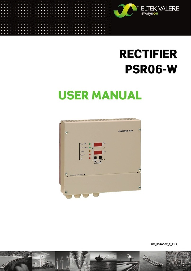
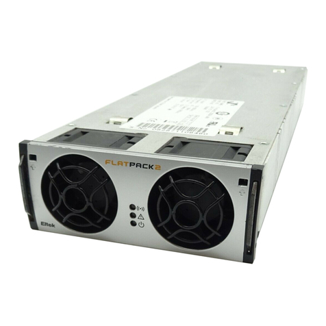
Eltek Valere Flatpack2 User manual

2029242 R2
Installation Guide
Flatpack2 -
48V 150A DC Po er Systems
Flatpack2 Power System

2
Installation Guide Flatpack2 -48V 150A ~ 2029242 R2, May 2008
Information in this document is subject to change ithout notice and does not
represent a commitment on the part of Eltek Valere.
No part of this document may be reproduced or transmitted in any form or by any
means—electronic or mechanical, including photocopying and recording—for any
purpose ithout the explicit ritten permission of Eltek Valere.
Copyright © 2008
Eltek Valere
1303 E Arapaho Rd
Richardson, TX 75081
USA
Phone: +1 (469) 330-9100
Fax: +1 (469) 330-9101
Technical Support
+1 (866) 240-6614
.eltekvalere.com
2029242
R2
,
ay
2008
Published 30 May 2008

Installation Guide Flatpack2 -48V 150A ~ 2029242 R2, May 2008
3
Table of Contents
1.
Safety and Compliance................................................................... 5
FCC Compliance Statement.............................................................................................5
2.
Introduction .................................................................................... 7
About This Guide................................................................................................................7
About This Revision (2) .....................................................................................................7
3.
echanical Installation................................................................... 8
System Unpacking.............................................................................................................8
Rack Mounting....................................................................................................................8
Rack Installation................................................................................................................... 8
Anchor the Cabinet............................................................................................................9
Equipment Rack “Frame Ground”...................................................................................... 9
Converter Shelf Installation.............................................................................................9
4.
Electrical Installation.................................................................... 10
Individual Feed ................................................................................................................. 11
Dual Feed .......................................................................................................................... 11
5.
odule Installation ....................................................................... 12
6.
Distribution ................................................................................... 13
LVD Options...................................................................................................................... 14
Central Office Ground .................................................................................................... 14
Configurations ................................................................................................................. 15
T o Battery, T o Load (2B 2L).......................................................................................15
T o Battery, T o Load, 12 GMT (2B 2L GMT) .............................................................16
T o Battery, Four Load (2B 4L).......................................................................................16
Four Load, 12 GMT (4L GMT)............................................................................................17
Six Load (6L)........................................................................................................................17
Breakers and Fuses ........................................................................................................ 18
Plug-in Breakers .................................................................................................................18
Plug-in Fuse Holders..........................................................................................................18
GMT Fuses ...........................................................................................................................20
Battery Connections...................................................................................................... 20
Load Connections ........................................................................................................... 21
7.
Alarm and Control Terminations .................................................. 22
Alarm Contacts................................................................................................................ 22
Configurable Inputs ........................................................................................................ 23
Temperature Probe Terminations............................................................................... 23
Symmetry Terminations................................................................................................ 24

4
Installation Guide Flatpack2 -48V 150A ~ 2029242 R2, May 2008
8.
Controller Access.......................................................................... 25
Controller Configurations.............................................................................................. 25
Smartpack Extended ........................................................................................................25
Smartpack Web..................................................................................................................25
Local Keypad Access ..................................................................................................... 26
Local Computer Access................................................................................................. 28
9.
Startup Checklists........................................................................ 29

Installation Guide Flatpack2 -48V 150A ~ 2029242 R2, May 2008
5
1. Safety and Compliance
WARNING: For safety, the po er supply is required to be reliably connected to
PROTECTIVE GROUND. The equipment is to be connected to supply mains by
qualified personnel in accordance ith local and national codes (e.g., NEC, CEC, etc).
Do not disconnect and reconnect I/O po er connectors during lightning storms.
The output of the po er supply is not intended to be accessible due to energy
hazards. Rack mounting must be performed in accordance ith instructions
provided by the manufacturer to avoid potential hazards.
A readily accessible disconnect device shall be incorporated in the building
installation iring for all AC connections. Select all breakers according to section
AC input requirements (page 11).
FCC Compliance Statement
This device complies ith Part 15 of FCC Rules. Operation is subject to the
follo ing t o conditions:
1. This device may not cause harmful interference, and
2. This device must accept any interference received, including
interference that may cause undesired operation.
WARNING: Changes or modifications to this unit not expressly approved by the
party responsible for the compliance could void the user's authority to operate this
equipment.
Protecting personnel against electrical shocks: The po er system cabling must be
done by qualified personnel in conformance ith local and national electrical codes.
Input voltages to rectifiers are at a dangerous level. Ensure that circuit breakers are
locked in the OFF position at the AC service panel before attempting to ork on the
po er system. Dangerous voltages may still be present at the terminals even if the
rectifiers are OFF. Use a voltmeter to verify the presence of such voltages. Do not
s itch circuit breakers to ON until the entire system has been assembled and you
have been instructed to do so according to the appropriate procedure. Improper
iring can cause bodily harm and equipment damage. Turn off all po er sources
before servicing units.
WARNUNG:
Schuetzen von Personal gegen elektrische Schocks. Die Spannungsversorgungs -
Leitungen darf nur durch qualifiziertes Personal in Anpassung mit Oertlichen und
nationalen elektrischen Codes ausgefuehrt erden. Unsachgemaesse Verdrahtung
kann koerperliche Verletzung und Schaeden verursachen. Eingangsspannungen von
der Netzspannungs - Versorgung Ihrer Hausanlage koennen unter Spannung stehen
beim Anschluss derLeitungen. Vesorgungsspannungen koennen bei
unsachgemaessen Gebrauch gefeahrliche Schaeden verursachen. Sorgen Sie dafür,

6
Installation Guide Flatpack2 -48V 150A ~ 2029242 R2, May 2008
dass die Cirquite Breaker in der aus position sind. Benutzen Sie ein
Spannungsmesser um sicher zu sein das keine Netzspannung mehr vorhanden ist.
Verg issern Sie sich das alle Schalter an Ihrem Gereat und in der Vesorgung beim
Anschluss abgeschaltet sind. Unsachgemaesse Verdrahtung kann koerperliche
Verletzung und an der Ausstattung Schaeden verursachen. Vor Wartungsarbeiten
am Gerät sind alle Netzkabel vom Stromnetz zu trennen, um die Gefahr eines
elektrischen Schlages oder andere mögliche Gefahren zu reduzieren.

Installation Guide Flatpack2 -48V 150A ~ 2029242 R2, May 2008
7
2. Introduction
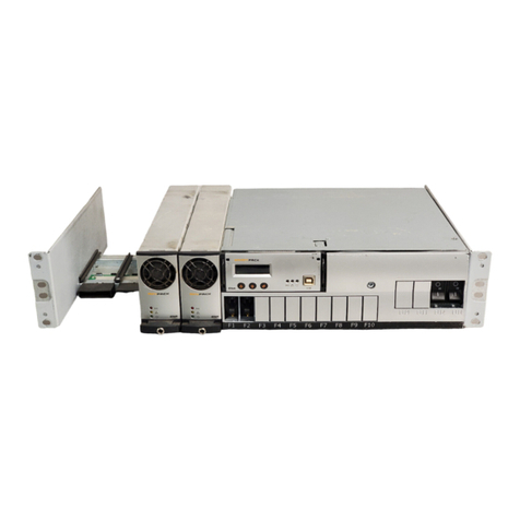
The Flatpack2 po er core consists of a 1U control and distribution panel and a 1U
rectifier shelf. Systems using the Flatpack2 -48V 150A design are ideal for sites
ith minimum available floor space. The compact size of this system allo s more
space for additional telecom equipment even ithin the same rack. This system is
mounted in a standard 19” or 23” telecommunications equipment rack. The
standard system configuration accommodates up to four (4) -48VDC Flatpack2 and
Flatpack2 HE rectifiers, providing a total po er output of 8kW.
Figure 1 -
Flatpack2 -48V 150A
System (2B 2L G T shown)
About This Guide
This manual provides a comprehensive overvie of and installation guidelines for
the Flatpack2 -48V 150A po er system. Additional information regarding
system components may be found in the follo ing documents:
o350002.013: User’s Guide—Flatpack2 Rectifiers
o350003.013: User’s Guide—Smartpack Monitoring & Control Unit
About This Revision (2)
A ne document format as adopted for this revision to reflect the transition to
the Eltek Valere brand. In addition, information from the Flatpack2 -48V 150A
Technical Bulletin (2033953) as incorporated into this manual.
Flatpack2 Rectifier Slots
(4)
Smartpack Controller
Distribution Section

8
Installation Guide Flatpack2 -48V 150A ~ 2029242 R2, May 2008
3. echanical Installation
U
SE OF FULLY INSULATED TOOLS IS REQUIRED WHEN WORKING WITH ANY POWERED
AC
OR
DC
CIRCUITS
.
THE SYSTEM IS TO BE MOUNTED OVER A CONCRETE SURFACE ONLY AND INSTALLED IN
R
ESTRICTED
A
CCESS
L
OCATIONS
(RAL).
A
CCESS MUST BE LIMITED BY USE OF TOOL
,
I
.
E
.
LOCK
AND KEY
.
The follo ing tools are required for the installation:
oStandard rench and/or socket set (1/4” to 1”)
oTorque rench, 10-40 Ft-lb range.
oTorque scre driver, 5-10 in-lb range.
oSmall flat blade scre driver (3/32” ide)
oStandard blade scre driver and Phillips tip scre driver
oWire cutters / strippers
oFork-lift truck or similar heavy equipment handling transport
oHoist ith lifting straps
oElectric drill and appropriate bits (a hammer drill may be required for concrete
flooring)
System Unpacking
An individual Flatpack2 -48V 150A unit is shipped in a box ith protective
packing material. If pre-installed in a cabinet or rack, the assembly is rapped
ith a shroud of high-strength plastic and bolted to a ooden pallet ith four
anchors. Rectifier modules and expansion options are packed in separate
cartons.
Exercise care hen unpacking and setting the equipment in place.
Rack ounting
The Flatpack2 -48V 150A system can be installed in a rack or an enclosure. The
mounting brackets are pre-installed at the factory and designed to be mounted
ithin a standard EIA 19” or 23” rack. Systems are designed to be mid-mounted.
Other mounting configurations may require additional support brackets.
Rack Installation
1) Use proper lifting equipment to position the Flatpack2 -48V 150A system
so that the holes in the support bracket are aligned ith the correct
mounting holes in the rack.
2) Use rack scre s to connect the system brackets to the desired positions
of the rack.

Installation Guide Flatpack2 -48V 150A ~ 2029242 R2, May 2008
9
Anchor the Cabinet
If the system is delivered installed in a mounting rack, anchor the cabinet before
installing rectifiers and batteries. Refer to the accompanying system installation
guide for rack feet diagrams and floor loading concerns.
Equipment Rack “Frame Ground”
Connections are located at rear of the rectifier rack ith chassis studs
provided in the AC input chamber. Refer to the NEC and any local codes
practices to determine the appropriate ire size. Use of paint-penetrating
ashers, abrasive compounds, or other means to achieve a reliable frame
ground is recommended.
Converter Shelf Installation
If Flatpack DC-DC converters are to be installed, refer to the manual
accompanying the converters for instructions on mounting and making system
connections.

10
Installation Guide Flatpack2 -48V 150A ~ 2029242 R2, May 2008
4. Electrical Installation
CAUTION: V
ERIFY THAT ALL
AC
CIRCUIT BREAKERS FEEDING THE SYSTEM ARE IN THE
OFF
POSITION
.
K
EEP ALL
AC
BREAKERS OFF UNTIL ALL APPROPRIATE SYSTEM CONNECTIONS
HAVE BEEN MADE AND VERIFIED
.
R
EFER TO SECTION
9
FOR STARTUP CHECKLISTS
.
WARNING:
F
OR SAFETY REASONS
(
HIGH LEAKAGE CURRENT AND HIGH TOUCH CURRENT
)
ALWAYS CONNECT THE
AC
EARTH WIRE
(PE)
TO THE TERMINALS BEFORE CONNECTING
AC
INPUT CABLE
(
S
).
Flatpack2 rectifiers have an input voltage range of 85 to 300 VAC (Nominal 185 –
275 VAC), ith a frequency range bet een 45 and 66Hz. See the User’s Gu de—
Flatpack2 Rect f er Modules (350002.013) for further details.
The AC junction box of each rectifier shelf contains a
knockout hole for a standard trade-size conduit ith a
diameter of 0.75”.
To ire the AC input terminal block:
1) Remove the cover located at the
rear of each rectifier shelf using a
Phillips scre driver (t o scre s).
2) Unscre and remove the green AC
connector using a Phillips or flat
blade scre driver.
3) Use a small flat blade scre driver to
open each terminal and install AC
iring. See the sections “Individual
Feed” on page 11 and “Dual Feed” on
page 11 for iring details.
4) Pull a green safety ire in the AC
mains conduit and terminate it to
the ground terminal of the
connector. It should be longer in length than the black and hite AC ires.
5) Double-check that each connection is secure and replace the connector.
6) If necessary, terminate additional safety ires to the
shelf ground termination stud located to the right of
the connector (see Figure 4 and Figure 5).
7) Replace the cover after AC terminations are
complete. Make sure to line up the bottom plate
bet een the guides on the bottom of the shelf.
Screws
Cov
er
Figure 3 - AC Terminal
Block (Removed)
Figure 2 - AC Input Cover

Installation Guide Flatpack2 -48V 150A ~ 2029242 R2, May 2008
11
Individual Feed
An individual feed shelf is fed by four (4) AC feeds; each feed supplies one
rectifier and should have 15A breakers. The figure belo illustrates the 9-pin AC
input connector. Termination points for Line 1,
Line 2, and Ground are listed in the table at right.
#12 AWG ire is recommended for each 15A
circuit, but up to #10 AWG may be used for each
feed termination position.
Figure 4 - Individual Feed Connector (Cover Removed)
Dual Feed
A dual feed shelf is fed by t o (2) AC feeds; each feed supplies t o rectifiers and
should have 30A breakers. The figure belo illustrates the 5-pin AC input
connector. Termination points for Line 1, Line 2, and Ground are listed in the
table at right. #10 AWG ire is recommended for
each 30A circuit.
Figure 5 - Dual Feed Connector (Cover Removed)
Pin
Description
1 Line 2, Rectifier 1 & 2
2 Line 2, Rectifier 3 & 4
3 Line 1, Rectifier 1 & 2
4 Line 1, Rectifier 3 & 4
5 Ground
Ground
T
ermination
Pin
Description
1 Line 1, Rectifier 1
2 Line 2, Rectifier 1
3 Line 1, Rectifier 2
4 Line 2, Rectifier 2
5 Line 1, Rectifier 3
6 Line 2, Rectifier 3
7 Line 1, Rectifier 4
8 Line 2, Rectifier 4
9 Ground
Ground
T
ermination
1
9
1
5

12
Installation Guide Flatpack2 -48V 150A ~ 2029242 R2, May 2008
5. odule Installation
CAUTION:
- Do not carry modules by the handles, even if they are arm
- Open the handles before inserting modules into shelves
Flatpack2 rectifiers incorporate an AC mains fuse in each line.
Double Pole / Neutral Fusing
Both the Smartpack controller and the Flatpack2 rectifier utilize the same locking
mechanism to keep the module fixed in place hen installed into a system shelf.
Typically, the Smartpack controller is delivered installed in the system. If it is not
pre-installed, make required connection to the back of the controller before
installing (see Section 7).
To install modules:
1) Release the handles by inserting a small flat-blade scre driver into the
release slots and pressing the tip up ard; extend each handle.
2) Slide the module firmly into the shelf.
3) Latch the handles to lock the rectifier in place.
To remove modules:
1) Release the handles by inserting a small flat-blade scre driver into the
release slots and pressing up.
2) Use the handles to pull the module out just far enough to here the body
can be held.
3) Slide the module out the rest of the ay. Do not carry it by the handles.
Flatpack2 rectifiers eigh just over 4 lbs (1.9 kg) each.
Device
hazard
Handle
Release

Installation Guide Flatpack2 -48V 150A ~ 2029242 R2, May 2008
13
6. Distribution
The Flatpack2 -48V 150A system consists of a 1U section for the controller and
distribution. When looking at the front, the Smartpack controller occupies the
leftmost position corresponding to the idth of one Flatpack2 rectifier slot in the
po er shelf belo . When vie ed from the rear of the system, the controller slot
occupies the rightmost position; the controller alarm board is accessible from this
side.
All termination points are located in the rear of the system and are stacked
vertically in pairs. For battery landings, the top cable landing is labeled “A” and is set
back to give clearance to the bottom landing, hich is labeled “B”; these landings
are labeled “1” and “2”, respectively, for load landings.
To make cable connections:
1) Remove the t o scre s securing the cover using a Phillips scre driver.
2) Make careful note of the labels for each landing before making connections.
Do not connect batteries until system turn-up.
3) Make connections ith a maximum #1 AWG cable ith t o-hole lugs having
1/4” diameter holes on 5/8” centers; 1/4-20 fastening hard are is provided.
4) Torque connections to 51-58 in-lbs.
Figure 6 – Rear Distribution Connections (4L G T shown)
Systems configured to accept GMT fuses have a 12-position GMT fuse block
installed in the leftmost distribution position (far right hen vie ed from the front).
The block is rated at a total of 65A, ith each position accepting up to a 15A fuse.
The positions are numbered 1 to 12 from r ght to left (see Figure 7). The top ro is
the “hot” or “output” terminal; the bottom ro is for returns. These terminals accept
ire sized from #22 AWG to #14 AWG.
Batteries
Loads
Returns
Loads
Loads
(G T Fuse Block)

14
Installation Guide Flatpack2 -48V 150A ~ 2029242 R2, May 2008
Figure 7 - G T Block Distribution Terminals
To ire the GMT fuse block:
1) Remove the t o scre s securing the cover using a Phillips scre driver.
2) Use a small flat blade scre driver to open the desired terminals (the clamp
scre is belo each terminal).
3) Strip load ire 3/8” and insert it into the top terminal.
4) Tighten the scre to secure the ire.
5) Strip the return ire 3/8” and insert it into the bottom terminal.
6) Tighten the scre to secure the ire.
7) Repeat for each remaining GMT position
LVD Options
A single lo -voltage disconnect (LVD) contactor can be
installed for either battery or load equipment. The
“Configuration” label (in front of the return bus to the right
of the “RETURN” label) describes hich of the three LVD
configuration options the distribution section contains:
LVBD (battery disconnect), LVLD (load disconnect), or NO
LVD.
Central Office Ground
A dedicated central office (CO) grounding conductor connection is recommended.
This conductor should be of the same or larger gauge than the largest system
conductor. It should be able to discharge total system current in a fault
condition. A THHN style cable is recommended. This cable should be installed
bet een the DC system point (as sho n) and the primary site ground bar. See
Figure 8 for the recommended organization of return connections.
1
12
Hot/Output Row
Return Row

Installation Guide Flatpack2 -48V 150A ~ 2029242 R2, May 2008
15
Configurations
Configurations for the Flatpack2 -48V 150A system are defined by the number of
breaker positions provided for batteries and load equipment. The follo ing are
common configurations:
Two Battery, Two Load (2B 2L)
The t o leftmost breaker position sets are populated, and the rightmost bus
set is not installed in the “2B 2L” configuration.
Figure 8 - Recommended Return Bus Organization
Battery Returns
Load Re
turns
CO Ground
Battery A
Battery B
Load 1
Lo
ad 2
Returns
Battery
Load

16
Installation Guide Flatpack2 -48V 150A ~ 2029242 R2, May 2008
Two Battery, Two Load, 12 G T (2B 2L G T)
This configuration comes ith t o battery breaker positions, t o load
positions, and a 12-position GMT fuse block in the rightmost section.
Two Battery, Four Load (2B 4L)
The “2B 4L” configuration populates all six plug-in positions. As usual, the
leftmost positions are dedicated to batteries; the rest are for load output.
NOTE: Battery breakers turn ON to the left; load breakers turn ON to the
r ght.
Figure 9 - Connections to G T Block (Rear View)
Battery A
Battery B
Load 1
Load 2
Load 3
Load 4
Batteries
Loads
1 & 2
Loads
3 & 4

Installation Guide Flatpack2 -48V 150A ~ 2029242 R2, May 2008
17
CAUTION: T
HE FOLLOWING CONFIGURATIONS FEATURE UNPROTECTED BATTERY
TERMINALS
.
I
T IS STRONGLY RECOMMENDED THAT EXTERNAL BREAKERS OR FUSES BE
INSTALLED BETWEEN THE SYSTEM AND BATTERIES
.
NOTE: When facing the front of the system, the leftmost load breakers in the
follo ing distributions turn ON to the left; the rest turn ON to the r ght.
Four Load, 12 G T (4L G T)
The “4L GMT” configuration changes the t o 100A battery breaker positions
into 60A load positions by tying them to the internal load bus. T o bulk,
unprotected battery landings are available in the rear of the system (see
Figure 10). The rightmost position is populated by a GMT fuse block.
Figure 10 - Bulk Battery and Protected Load Landings
Six Load (6L)
This configuration differs from the “4L GMT” system only in that, rather than a
GMT fuse block, the rightmost position is populated by a set of parallel load
buses.
Batteries
Loads
1 & 2

18
Installation Guide Flatpack2 -48V 150A ~ 2029242 R2, May 2008
Breakers and Fuses
CAUTION:
SIGNIFICANT EXTRACTION FORCE IS REQUIRED TO REMOVE DISTRIBUTION
DEVICES DUE TO THE CONTACT PRESSURE REQUIRED FOR HIGHLY RELIABLE
,
LOW
-
TEMPERATURE RISE CONNECTIONS
.
Up to six distribution busses, arranged into three sets of t o, can be configured
to receive plug-in breakers or plug-in fuse holders from the front of the Flatpack2
-48V 150A system. Plug-in positions are like ise grouped into a maximum of
three sets of t o positions, ith each set stacked vertically and oriented
horizontally.
Do not use any type of clamps, pliers, or other hard tools to remove distribution
devices as the housing may be cracked by excessive force. Damaged distribution
device represent an operational hazard and should never be used.
Figure 11 - Plug-in Disconnect Device Positions (2B 4L shown)
Plug-in Breakers
Auxiliary contact circuit breakers are standard over-protection devices used
this distribution. All breakers are connected to system alarming so that an
open breaker ( hether tripped or manually placed in the OFF position) triggers
a “Load Distribution Alarm” in the Smartpack controller. Breakers should be
removed from any unused positions to prevent nuisance alarms. Single-pole
circuit breakers rated up to 100A can be installed. Each set of positions also
accepts a t o-pole breaker rated up to 175A.
Plug-in Fuse Holders
As an alternative to plug-in circuit breakers, plug-in fuse modules may be
installed. The same considerations regarding insertion and removal of
breakers should be observed.
A plug-in fuse assembly consists of three main parts: A fuse, an alarm fuse
indicator, and a plug-in module. If the main fuse element opens, the alarming
fuse also opens, giving a visible indication of a fault condition; a signal is then
sent via the Smartpack alarm board that activates the remote system
monitor. The alarming fuse must be replaced henever a ne main fuse is
required. A fuse holder may be removed and inserted into the plug-in module
at any time; it is not necessary to remove the plug-in module to replace the
fuse.
Two (2) Plug-
in Positions
per Set
Three (3) Sets of Plug-in
Positions (maximum)

Installation Guide Flatpack2 -48V 150A ~ 2029242 R2, May 2008
19
NOTE: If breakers or fuse-holders are not installed in the correct orientation,
the alarm may not signal properly hen a device opens.
To install plug-in breakers or fuse-holders for LOAD:
1) Remove the t o scre s holding the front cover in place using a Phillips
scre driver.
2) Orient the “LINE” and “LOAD” bullets to the correct bus. The leftmost
breaker set (next to the Smartpack controller) has LINE to the right
and LOAD to the left; the actuator turns ON to the left. The other
positions have LINE to the left and LOAD to the right; the actuator
turns ON to the r ght.
To install plug-in breakers or fuse-holders for BATTERY (if used):
1) Connect the battery alarm ire to the device’s normally closed (NC)
alarm pin.
2) Orient the “LINE” and “LOAD” bullets to the correct bus. The battery
breaker set (next to the Smartpack controller) has LINE bus to the right
and its LOAD bus to the left; the actuator turns ON to the left.
Securely insert device into the receptacles.
3) Remove fuses and turn breaker actuators OFF until system turn-up.
Figure 12 - Proper Battery Breaker Orientation and Alarm Connection
Battery Breaker
Alarm Wires
Indicator
fuse (G T)
TPS Fuse
Holder
Plug-in
odule

20
Installation Guide Flatpack2 -48V 150A ~ 2029242 R2, May 2008
G T Fuses
T elve (12) GMT fuse positions are provided in a standard
block, hich is rated for a maximum of 65A (total). GMT fuses
rated from 1/8A to 15A can be used in each position. Open
fuses are easily identified by the graduated movement of the
metal fuse tab. The tab moves in a manner that exposes the
colored tip to indicate a failed circuit. If installed, the GMT fuse block
populates the rightmost disconnect device position.
From the front, the fuse positions are numbered 1 to 12 from left to r ght.
Naturally, the numbering is reversed hen vie ed from the back.
Battery Connections
CAUTION: D
O NOT CONNECT BATTERIES UNTIL SYSTEM TURN
-
UP
.
F
OLLOW THE
CHECKLIST PROVIDED FOR THE PROPER PROCEDURE
.
Every distribution configuration of the Flatpack2 -48V 150A system features t o
battery termination points. When vie ed from the rear, the battery bus landings
take up the one of the rightmost positions of the distribution section, just to the
left of the Smartpack alarm board. A label reading “BATT (-)” appears directly in
front of the landings.
There are t o possible configurations for battery connections: With breaker
positions or ithout breaker positions.
If breaker positions are utilized, the battery busses take up the rightmost
position hen the system is vie ed from the rear. The corresponding breaker
positions are located to the right of the Smartpack controller at front (leftmost
position hen facing the front of the system).
NOTE: Battery breakers turn ON to the left and OFF to the r ght.
If there are no breakers installed, the battery busses take up the position just to
the left of the bus ith breaker positions and to the immediate right of the
return bus. In this case, the rightmost busses may be used for load output. In
every case, make sure to check the labels before connecting batteries to the
system.
1
12
Other manuals for Flatpack2
2
Table of contents
Other Eltek Valere Power Supply manuals
Popular Power Supply manuals by other brands
Agilent Technologies
Agilent Technologies 654xA Series operating manual

Lathem
Lathem PS8-2412 Specifications

Rockwell Automation
Rockwell Automation Allen-Bradley SensaGuard 440N-Z21 Series installation instructions
Goobay
Goobay DF 1730 LCD manual

Power One
Power One SFP450 Series Programming manual

Cooler Master
Cooler Master Silent Pro Platinum RS-550-SPPA user guide
