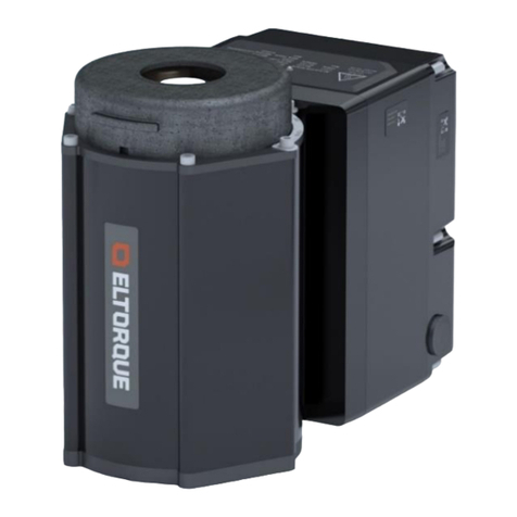
Eltorque QT50 User manual

Doc ID 1321 version 2.0 Sept. 2018
User Manual QT50

www.eltorque.no
Table 1: Document history for User Manual QT50
Document ID Version
Author Changes Approved by Date
1321 1.7 KK KK June 2017
1321 1.8 KK KK Nov. 2017
1321 1.9 SK Added info on harness KK Feb. 2018
1321 2.0 SK New layout and structure KK Sept. 2018
Copyright © 2018, Eltorque AS
This document is submitted in confidence and contains proprietary information which shall not be
reproduced or transferred to others for the purpose, tender or any other intensions without written
permission of Eltorque AS

User Manual QT50 Doc ID 1321 version 2.0 Sept. 2018 Page 3 of 62
Table of Contents
Introduction ......................................................................................... 5
System Overview ................................................................................................. 5
Description ........................................................................................................... 6
Features ............................................................................................................... 6
Area of use .......................................................................................................... 7
Technical support information ............................................................................. 7
Reader groups ..................................................................................................... 7
Notation used in this manual ............................................................................... 7
Related documentation ........................................................................................ 8
Disclaimer ............................................................................................................ 8
Terms and abbreviations ..................................................................................... 8
About this user manual ...................................................................................... 11
HSE Information ................................................................................ 13
Care and cleaning of actuator ........................................................................... 13
Disposal and waste handling ............................................................................. 13
Product Description .......................................................................... 15
QT50 actuator .................................................................................................... 15
Actuator control system examples ..................................................................... 16
Technical specification....................................................................................... 17
Actuator Components ........................................................................................ 19
QT50 External construction ------------------------------------------------------- 19
Communication interface ................................................................................... 19
Labelling ............................................................................................................ 21
Cabling ............................................................................................................... 21
Storage .............................................................................................................. 22
Engineering ........................................................................................................ 22
Power circuit design ----------------------------------------------------------------- 22
Duty performance -------------------------------------------------------------------- 22
Endurance ----------------------------------------------------------------------------- 23
Shielding considerations ----------------------------------------------------------- 23
Installations with Eltorque Hybrid Marine Cable ------------------------------ 25
Orientation ----------------------------------------------------------------------------- 26
Space requirements ----------------------------------------------------------------- 27
Mounting ------------------------------------------------------------------------------- 29
Information when an actuator/valve adaption is needed. ------------------ 29
Torque considerations for valve and actuator--------------------------------- 30
Closing time --------------------------------------------------------------------------- 30
Configuration -------------------------------------------------------------------------- 30
Mounting and Installation Instructions ........................................... 31
Mounting the actuator on the valve ................................................................... 31
Mounting procedure QT50 ................................................................................. 31
Valve flange fastening holes .............................................................................. 32
Cable connection overview ................................................................................ 33
Cable glands ...................................................................................................... 37
Power supply connection ................................................................................... 37

Table of Contents
Page 4 of 62 User Manual QT50 Doc ID 1321 version 2.0 Sept. 2018
Grounding (earthing).......................................................................................... 38
Communication connection interfaces ............................................................... 39
Connection procedure -------------------------------------------------------------- 39
CANopen interface connection --------------------------------------------------- 39
Digital interface connection -------------------------------------------------------- 41
Analog interface connections ----------------------------------------------------- 42
Operation ........................................................................................... 44
Manual operation ............................................................................................... 45
Error alarms and error handling ......................................................................... 46
GENERAL alarm --------------------------------------------------------------------- 46
POSITION UNDEFINED alarm --------------------------------------------------- 46
TEMPERATURE alarm ------------------------------------------------------------- 47
TORQUE alarm ---------------------------------------------------------------------- 47
Troubleshooting ................................................................................................. 47
Maintenance ...................................................................................... 49
Maintenance overview ....................................................................................... 49
Inspection .......................................................................................................... 49
Tightening of valve/ actuator bolts ..................................................................... 49
Lubrication ......................................................................................................... 49
Care and cleaning of anodizing ......................................................................... 49
Technical Details ............................................................................... 51
Power consumption ........................................................................................... 51
Surface treatment .............................................................................................. 51
Communication interface ................................................................................... 51
CANopen interface ------------------------------------------------------------------ 52
Digital interface ----------------------------------------------------------------------- 52
Analog interface ---------------------------------------------------------------------- 53
Ordering Information and Recommended Spare Parts ................. 55
Torque and Screw Recommendations ............................................ 57
A. 1. Eltorque torque recommendations .................................................................... 57
A. 2. Mounting screws and lubrication ....................................................................... 57
Earthing Methods in Maritime Installations .................................... 59

User Manual QT50 Doc ID 1321 version 2.0 Sept. 2018 Page 5 of 62
Introduction
.
System Overview
The Eltorque Lifelong Intelligent control concept provides maintenance-free,
configurable eco-friendly and fully electric actuators with real-time feedback.
The Eltorque actuators are divided in two main families:
QT-series of actuators are ideal for quarter-turn valves such as butterfly and
ball-valves.
MT-series of actuators are multi-turn actuators optimized for linear valves
such as globe valves, and with a form factor that make the MT-series ideal for
manifold actuation.
The Eltorque actuators are fully electric and can be connected in series. They
offer a plug and play solution with low installation costs and high level of
security. By combining the Eltorque actuators with the Eltorque Hybrid Marine
Cable, the cost of installation is even further reduced.
The Electric serial connected actuator installation eliminates the cable clutter,
transportation loss, air or oil leakage associated with conventional actuator
installations.
The use of permanent magnet-based motor technology and efficient electric,
mechanics and firmware design guarantee an eco-friendly and cost-efficient
ownership.
Eltorque actuators have a proven track record of lifelong maintenance-free
operation with 15 years of proven operation.
Figure 1: System overview example

Table of Contents
Page 6 of 62 User Manual QT50 Doc ID 1321 version 2.0 Sept. 2018
Description
The QT50 described in this user manual is the smallest actuator in the Eltorque
QT-series. This series is characterized by their quarter-turn movement and low
energy consumption along with their small footprint. They are suited for
butterfly, ball and other quarter-turn valves. The QT50 can be used in
conjunction with Eltorque Hybrid Marine Cable and is a part of the Eltorque
lifelong intelligent control concept.
Table 2: Product overview
Product Product id User Manual
QT50 CANopen Actuator with
connection harness
50.120.1A Doc ID 1321
version 2.0
QT50 CANopen Actuator with harness
and Hybrid Cable 2
50.120.1AH
QT50 Digital Actuator with harness 50.110.1A
QT50 Analog Actuator with harness 50.130.1A
QT50 CANopen Actuator without
connection harness
50.120.1 Doc ID 1321
version 1.9
QT50 CANopen Actuator without
harness but with Hybrid Cable 2
50.120.1H
QT50 Digital Actuator without harness 50.110.1
QT50 Analog Actuator without harness 50.130.1
Features
The Eltorque actuators provides a wide range of attractive features:
Optimized single-axis architecture, ensuring a compact and low-weight
actuator.
Accurate real-time magnetic position control with no mechanical limit
switches, ensuring maintenance-free operation.
Few spare parts - low lifetime costs.
Easy setup and commissioning – low installation cost.
Specific alarms including over-torque and temperature – providing high
operation safety.
Robust implementation of CANbus ensuring a reliable serial connection.
Self-lock feature which allows movements from the motor, but locks
movements from the gear side.
Remote programming via the CAN cable.
Specific alarms including over-torque and temperature – providing high
operation safety.
Fast and precise motor reduces the closing time.

Introduction
User Manual QT50 Doc ID 1321 version 2.0 Sept. 2018 Page 7 of 62
Area of use
Eltorque actuators are an ideal choice in a wide range of Maritime and Onshore
systems including, but not limited to:
Cargo handling
Bilge and ballast
Tank gauging
SPS system
Anti-heeling systems
RSW systems
Bulk handling
Fuel systems
Hydro power and district heating
Waste water treatment
HVAC system
Fire water system
Oil Production system, oil transfer line
Technical support information
If you require technical support outside of this manual, we recommend that you
use the support functions available on the web-site or contact us via e-mail.
If you have feedback to this manual, that should also be routed through e-mail.
Eltorque AS
Julianus Holms veg 34
7071 Trondheim
Norway
Web: www.eltorque.no
e-mail: inf[email protected]
Phone: +47 74 85 55 20
Fax: +47 74 85 55 12
Reader groups
The following reader groups have been defined for this User Manual:
Project and engineering personnel
Installation personnel
Operators
Supervisors
Technical support personnel
Technical management personnel
Notation used in this manual
The following notations have been used in this manual:
Bold is used for commands and menu selection
Italic is used to give emphasis to information. It is also used for names of
documents referred to in the manual.
Note! Note is used to draw attention to important or helpful information.

Table of Contents
Page 8 of 62 User Manual QT50 Doc ID 1321 version 2.0 Sept. 2018
Caution! A caution is used when there is a danger that the equipment is damaged if
you do not follow the instructions.
Warning is used to draw attention to information of very high importance,
for example to avoid injuries to personnel.
Related documentation
This User Manual QT50 refers to the following documentation.
Table 3: Related documentation
Document Document ID
QT50 product data sheet Eltorque document ID 2140
Hybrid Marine Cable data sheet Eltorque document ID 1946
Eltorque E3C Manual Eltorque document ID 1687
Guidelines for earthing in maritime
installations
Published by the Norwegian Electrical Safety
Directorate. Available on net or supplied by
Eltorque on request.
System Integrators Manual
CANopen Interface
Eltorque document ID 1691
Disclaimer
The information contained in this document is subject to change without prior
notice. Eltorque AS shall not be liable for errors contained herein or for incidental
or consequential damages about the furnishing, performance, or use of this
document. It is the customer’s responsibility to verify that he has the latest
revision available by checking the document area of www.eltorque.no
Terms and abbreviations
Table 4: Terms and abbreviations
Term Description
ABS American Bureau of Shipping.
AFD Asbestos Free Declaration.
Analog Control Step-less control utilizing analog signals, e.g. 4-20 mA. Allows positioning of the
valve actuator between Open and Closed.
BTO Break to open.

Introduction
User Manual QT50 Doc ID 1321 version 2.0 Sept. 2018 Page 9 of 62
Term Description
CAN/CANbus
Controller Area Network.
CANbus is a fieldbus which allows communication between a maximum of 127
actuators connected to the same network. It is not a “master-slave” network (ref.
Modbus), hence all the nodes in the network can actively send messages at their
own initiative. Communication is prioritized meaning that urgent messages are
transmitted and received before information with lower priority. Compared to
Modbus, CANbus has quite a few advantages:
More reliable communication
More nodes per network
More control and configuration features are available
Higher performance
CANopen
CANopen is a higher-level protocol and is running on top of the CAN protocol for
all Eltorque actuators.
The standard consists of an adressing scheme for the nodes on the CAN bus and
several small protocols for communicating with each node. In terms of the OSI
model, CANopen implements the levels above, including the network layer.
CCS Central Control System.
Communication
Interface Box
Electronic device controlling the actuator according to signals from an overall
control system such as a PLC or other type of electronic controller.
Configuration The set-up of parameters, which affects the actuator’s performance and behavior.
Digital Control Simple control utilizing relays, on/ off switches and indicators. Allows only Open
or Closed functionality for a valve actuator.
DNV GL Det Norske Veritas Germanischer Lloyd.
E3C Eltorque Common Configuration Controller.
E-VCI Eltorque Valve Control Interface
E-VCS
Eltorque Valve Control System offers a dedicated control system
for operation of Eltorque actuators.
Eltorque Valve Control System is suitable for installations where the operator
requires full control of all valves and pumps, and in addition monitor level,
temperature, flow and pressure.
Hazardous area
Area in which the permanent or periodical presence of explosive substances
causes a risk of explosion.
Products described in this manual are not suitable for use in hazardous areas.
Eltorque can deliver actuators for use in such areas if required. Please contact
your local representative for further details.
HMI Human Machine Interface.
HSE Health, Safety and Environment.
HVAC Heath, ventilation and air condition
IACS International Association of Classification Societies
IAS Integrated Automation System.
ICS Integrated Control System.
IMO International Maritime Organization
LR Lloyd’s Register.
MAST Maximum allowable stem torque/thrust.
MD Material Declaration.
MEPC The Marine Environment Protection Committee

Table of Contents
Page 10 of 62 User Manual QT50 Doc ID 1321 version 2.0 Sept. 2018
Term Description
OSI model
Open Systems Interconnection model. The model is a conceptual model that
standardizes communication systems without regard to the underlying internal
structure. The model partitions a communication system into abstraction layers.
Out of range Definition of position. The outgoing shaft is outside the defined position area.
PF Power factor
PCB Printed circuit board.
PLC
A Programmable Logic Controller is a digital computer used for automation of
industrial processes, such as control of machinery on factory assembly lines,
measurement and control of process plants etc.
RSW Refridgerated sea water system
SDoC Supplier Declaration of Conformity.
SOLAS
Safety Of Life At Sea – conversion under IMO concerning safety for personnel and
ships at sea
VA Voltampere
UPS Uninterruptable power supply.
Valve
A valve is a device that controls the flow of materials (gases, fluidized solids,
slurries, or liquids) by opening, closing, or partially obstructing various
passageways.
This manual refers to quarter-turn valves with a 90 degrees movement between
Closed and Open position.
Valve actuator A device for control of valves in various process control systems.
Valve top
flange
The flange on top of the valve which integrates the actuator. Key parameters to
be aware of are summarized in 3.3 Technical specification on page 17.
As an example, most butterfly valves comprise four screw holes for the flange
integration and a square stem for valve operation.
Within range Definition of position. The outgoing shaft is within the defined position area.

Introduction
User Manual QT50 Doc ID 1321 version 2.0 Sept. 2018 Page 11 of 62
About this user manual
This user manual describes the guidelines for installation, setup and operation of
QT50 in a valve control system. The valid products for this manual are listed in
Table 2: Product overview on page 6.
Chapter 1 introduces the product and this manual.
This chapter is intended for all reader groups.
Chapter 2 informs on health, safety and environment issues.
The reader group for this chapter is for supervisors, technical support and
technical management personnel.
Chapter 3 gives a product description including the mechanical construction of
the actuator, technical specifications and a functional description. There is also
an overview of technical issues that should be considered in the design and
planning phase for the installation.
The reader group for this chapter is supervisors, project and engineering
personnel.
Chapter 4 covers the mechanical installation on valves and the electrical
installation of power and control signal.
The reader group for this chapter is installation personnel.
Chapter 5 covers the use of the actuator such as how to use the manual
emergency operation. There is also an overview of error messages and a
troubleshooting overview.
The reader group for this chapter is operators.
Chapter 6 covers maintenance, inspection and repair of the actuator.
The reader group for this chapter is operators, technical support and
management personnel.
Chapter 7 gives more in-depth technical information on the product.
The reader group for this chapter is technical support and management
personnel.
Chapter 8 gives ordering information.
The reader group for this chapter is technical support and management
personnel.
Appendix A gives an overview of torque recommendations.
The reader group for this chapter is installation personnel.
Appendix B includes the document “Earthing Methodology in Maritime
Installations” The reader group for this chapter is installation personnel,
technical support and technical management personnel.

Table of Contents
Page 12 of 62 User Manual QT50 Doc ID 1321 version 2.0 Sept. 2018
This page is left intentionally blank

User Manual QT50 Doc ID 1321 version 2.0 Sept. 2018 Page 13 of 62
HSE Information
This chapter includes safety information that the user needs to know to operate
the equipment without doing harm to personnel or the environment.
The operation of the equipment is safe provided that the recommended
operating procedures are followed. There are specific hazards however
that need to be addressed so that the user knows how to deal with them.
Electrical installations shall be designed and installed by personnel with
certifications according to applicable laws and regulations. Ensure that all
such work is done according to applicable laws and regulations.
Service must always be performed by trained personnel.
Care and cleaning of actuator
Caution! Do not use ammonia, alkaline cleaners, lye or strong acid for cleaning as
this can damage the protective anodized layer of the product surface.
Caution! Do not use high pressure power washer directly on the actuators as the
product is not IP69K rated.
Disposal and waste handling
All batteries and electronic equipment may contain substances harmful to the
environment. After removing used equipment, return them for disposal
according to local governmental guidelines.

HSE Information
Page 14 of 62 User Manual QT50 Doc ID 1321 version 2.0 Sept. 2018
This page is left intentionally blank

User Manual QT50 Doc ID 1321 version 2.0 Sept. 2018 Page 15 of 62
Product Description
QT50 is the smallest quarter-turn actuator in the Eltorque portfolio. It has been
used on a various of vessel types on butterfly and ball valves. It is equipped with
a magnetic position sensor that gives a correct position feedback, even after a
power outage. It can be manually operated by the means of a fixed hand wheel
located under the cover on top of the actuator without the need for external
tools.
QT50 actuator
The QT50 actuator is suitable for valves with torque requirements of 10 - 50 Nm,
it can be delivered with CANopen, Analog and Digital communication.
The actuator is designed to be operational during a temporary submerged
situation, see details for housing in Table 5: System performance parameters for
QT50 actuators on page 17.
Caution! Remember to have the actuator checked by Eltorque after all submerged
situations to keep the warranty.
Figure 2: QT50 mounted on valve

Product Description
Page 16 of 62 User Manual QT50 Doc ID 1321 version 2.0 Sept. 2018
Actuator control system examples
The actuator must be integrated with the main control system in one of two
ways:
Directly to the main control system. In this case it is important to consider
the communication protocol.
Through a stand-alone sub-system delivered by Eltorque. This is a
standardized hardware and software platform tailored for Eltorque actuators.
The solution illustrated below show a serial connection with the Eltorque Hybrid
Marine Cable. This cable can be used with the CANopen communication
interface. In addition, QT50 actuators support Digital and Analog connections.
Figure 3 below shows Eltorque actuators that are connected to a cabinet with
Eltorque valve control system (E-VCS). In this example, pump starters are also
connected to the E-VCS. Other equipment, such as sensors can also be connected
to the E-VCS. The E-VCS includes an HMI interface on the cabinet and can also
support an HMI interface on main control level.
Figure 3: Eltorque Valve Control System (E-VCS) with valve and pump control
Figure 4 below shows Eltorque actuators that are connected directly to a
customer specific PLC, PC or other control unit.On a system level, the PLC, PC or
Controller must be compliant with Eltorque communication protocol according to
Eltorque System Integrators Manual, see Table 3: Related documentation on page
8. Please contact your Eltorque representative for further information.

Product Description
User Manual QT50 Doc ID 1321 version 2.0 Sept. 2018 Page 17 of 62
Figure 4: Eltorque actuator loop connected to Integrated Automation Control System (IAS or ICS)
Technical specification
Table 5: System performance parameters for QT50 actuators
Feature Value
Torque options 10,20,30,40 or 50 Nm
Closing time options 0 - 90° movement
5, 8 or 15 sec. Recommended 8 sec.
Valve spindle adapter SQ11 depth 12 mm /0.5 in. For valve stem with free height more than
12 mm/0.5 in, a distance ring is needed, see chapter 3.9.9 on page 29.
Max. allowed valve
flange and related
torque
(Ref. ISO5211) 2001E
F04 F05 F07
63 Nm 125 Nm 250 NM
Valve applications Quarter-turn.
Examples:
Butterfly DN25-DN80 PN16
Weight 4.5 kg/ 9,92 lb
Dimensions (HxWxD) 163 x 118 x 164 mm
9.02 x 6.14 x 8.23 in
Manual operation –
number of turns 19 turns on hand-wheel = 90 movement on valve
Color Black
Housing
IPx6 and IP x8 (10 m – 72 hours/32 ft 9.7 in – 72 hours).
Should not be exposed to corrosive chemicals
External materials: anodized aluminum and flame-retardant PA.
Storage temperature 5 - 35C/41 - 95F

Product Description
Page 18 of 62 User Manual QT50 Doc ID 1321 version 2.0 Sept. 2018
Feature Value
Operating temperature -25 to 70C/-13 to 158F
Temperature protection Motor current is switched off in case of over-heating.
Power supply 1-phase,110 – 230V AC, 50/60 Hz, Max 140 VA
Power consumption
Opening and closing
with max torque
40 VA, PF 0.5
Power consumption
Standby (with 70%
holding torque
11VA, PF 0.3
Inrush current (worst
case)
During start-up the inrush current might be high. See chapter 7.1 for
more information. Eltorque can also assist with experience data for
product types and fuse selection.
Duty performance
According to AN 15714-
1 / IEC 60034-1
Class A – 10 cycles per hour/S2 – 15 min.
Endurance
According to EN 15712-
2
Classes A and B – 10 000 cycles per lifetime.
Cable glands Up to four M20 glands allows serial connection of power supply and
signal wiring. Use IP68 (10 m 72 hours) glands for all wires.
Communication
Interfaces options
CANopen allows positioning and other extended control of the
actuator. The absolute maximum theoretical number of devices allowed
on the bus is 127, but the actual number of nodes is limited by the
baud-rate and the cable quality. Eltorque recommends a maximum of
80 nodes on 500 m/1660ft cable.
Digital 2 DI (Open-Close) and 3 D0 (Open-Close-Alarm).
Analog Al (Set position) A0 (Feedback position) and D0 (Alarm) (4-20
mA) AI/A0 signal.
Position sensor
Resolution: 360°/12bit = 0.35156°/bit
Integral Non-Linearity (INL): typ. ± 0.8°
Differential Non-Linearity (DNL): ± 0.176°
Output shaft accuracy: 1%
Position feedback not corrupted by power outage.
Configuration USB connection to PC with Eltorque E3C. Special configuration cable is
needed, see E3C User Manual.
Configurable parameters
Open and Closed positions. Actuator speed, torque and valve position
regions. Inverted IO or bus parameters depending on the applied
communication interface.
Manual operation Standard feature using fixed hand-wheel. Mechanical valve position
indicator. No need for external tools.
Cover of hand-wheel
Can be removed and refitted without tools. Protects mechanism against
mechanical damage and foreign objects. The actuator must not be
lifted by the top cover.
Self-lock
The QT50 is equipped with a mechanical self-locking device that locks
the valve to the target position when the actuator movement command
is completed.
Certification/type
approval
Type approved by DNV-GL.
All valid certificates are listed on www.eltorque.no – support – technical
support – certificates.

Product Description
User Manual QT50 Doc ID 1321 version 2.0 Sept. 2018 Page 19 of 62
Feature Value
Position indicator light
Green: Open
Blinking green: Moving towards open
Yellow: Close
Blinking yellow: Moving towards close
Blinking red: Alarm
Blue: Reached position between Open and Close (for regulation
purposes)
Actuator Components
QT50 External construction
Figure 5: External Construction
Communication interface
The communication interface boards provide connectors for power, control
signals and configuration media.
The harness connects directly to the interface boards and are easily pulled out in
order to make connections, see Figure 6 for more details.

Product Description
Page 20 of 62 User Manual QT50 Doc ID 1321 version 2.0 Sept. 2018
Figure 6: Connection harness (with CANopen connector)
In older versions of the QT50 the connections must be done directly on the
connection board. This is described in version 1.9 of this manual, (document ID
1321 v. 1.9).
The QT50 can be delivered with the following interfaces.
CANopen – interface using the CAN (Controller Area Network)
communications standard. Eltorque recommends a maximum of 80 nodes on
500 m / 1660 ft. cable.
Digital – interface allowing simple Open & Close operation of valves.
Actuators with Digital Interface can be controlled directly from a conventional
panel with buttons/switches and indicator lamps. Alternatively, it can be
controlled from a PLC with digital inputs and outputs.
Analog – interface allowing regulating valves where positioning of the valve
is needed. The actuator provides continuous feedback of its actual position,
for comparison between desired and actual position.
Note! The QT50 does not provide a Modbus interface. If a Modbus interface is required,
please contact your Eltorque representative to find a solution.
More technical details on the different communication interfaces is given in
Chapter 7 Technical Details on page 51.
Table of contents
Other Eltorque Controllers manuals
