7
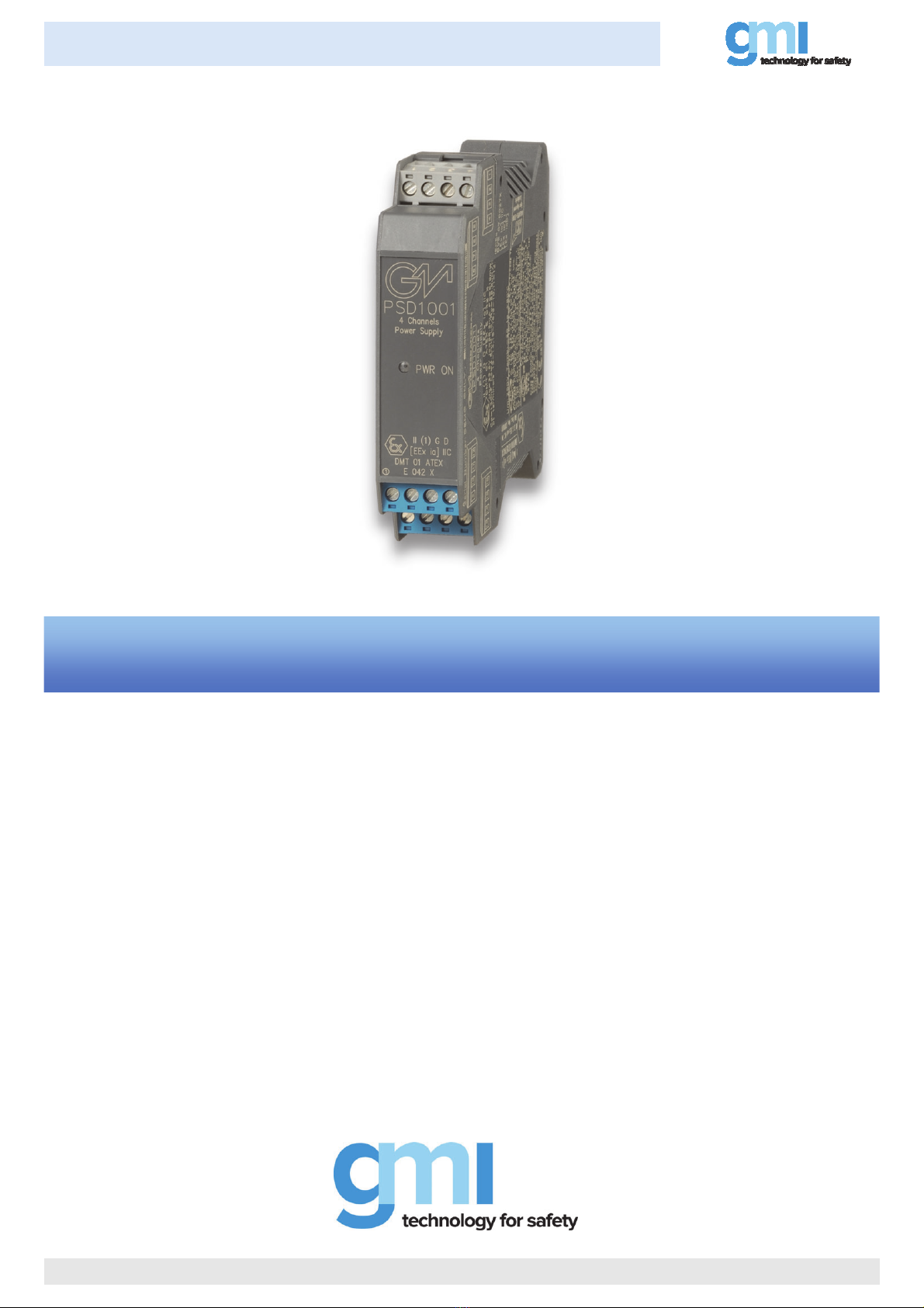
PSD1001 - SIL 3 - SIL 2 Quad ch. Power Supply for Hazardous Area EquipmentG.M. International ISM0023-11
PSD1001 is an isolated Intrinsically Safe Associated Apparatus installed into standard EN50022 T35 DIN Rail located in Safe Area/Non Hazardous Locations or Zone 2, Group IIC,
Temperature Classification T4, Class I, Division 2, Groups A, B, C, D, Temperature Code T4 and Class I, Zone 2, Group IIC, IIB, IIA Temperature Code T4 Hazardous Area/Hazardous
Locations (according to EN/IEC60079-15, FM Class No. 3611, CSA-C22.2 No. 213-M1987, CSA-E60079-15) within the specified operating temperature limits Tamb -20 to +60 °C,
and connected to equipment with a maximum limit for AC power supply Um of 250 Vrms.
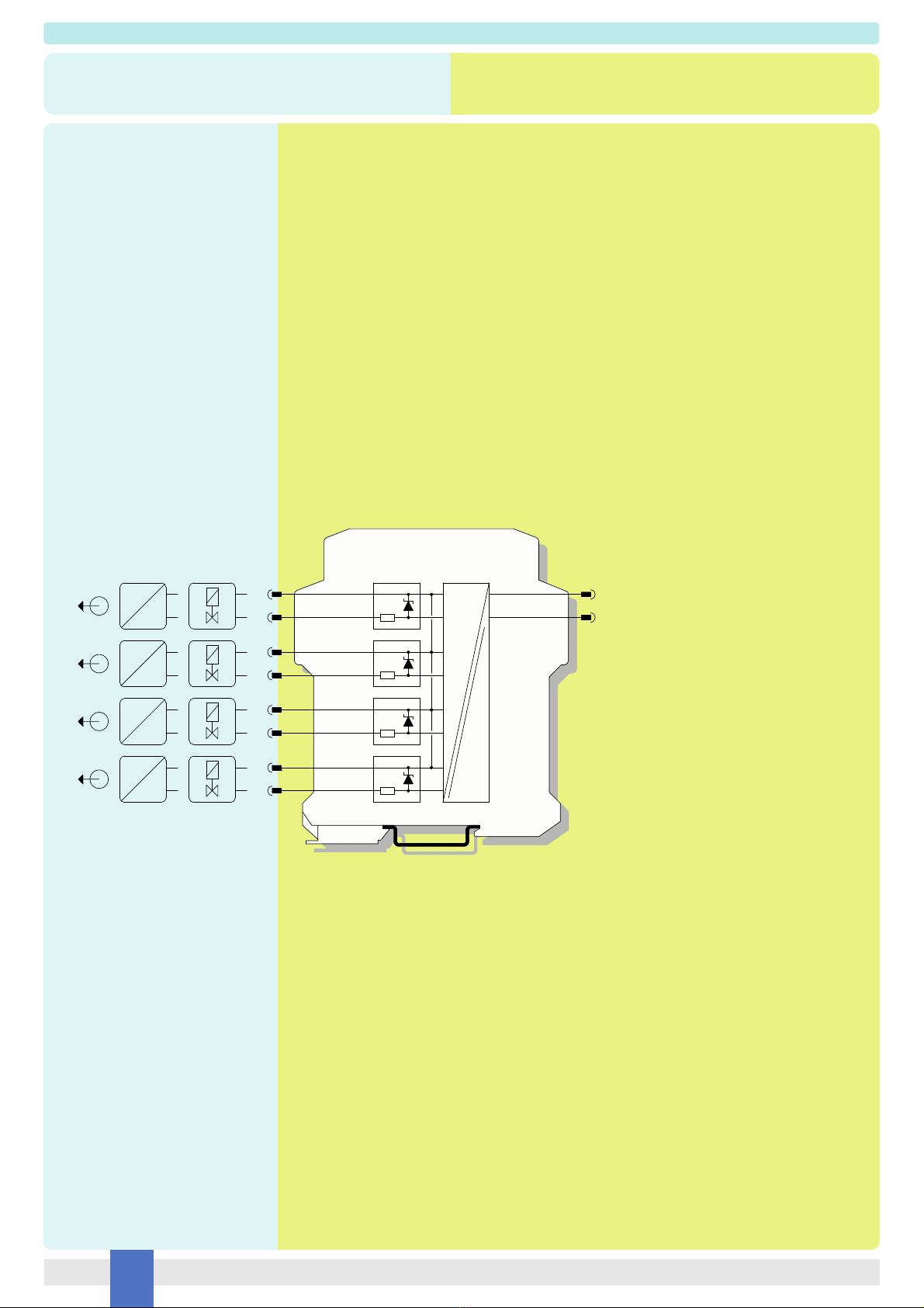
NOTE: outputs can be paralleled to increase output power. When combining outputs, consider Safety Parameters matching with the field device and allowable Group as shown in the
Safety Parameters Table and check that requirements are met.
Non-incendive field wiring is not recognized by the Canadian Electrical Code, installation is permitted in the US only.
For installation of the unit in a Class I, Division 2 or Class I, Zone 2 location, the wiring between the control equipment and the PSD1001 associated apparatus shall be accomplished
via conduit connections or another acceptable Division 2, Zone 2 wiring method according to the NEC and the CEC.
Not to be connected to control equipment that uses or generates more than 250 Vrms or Vdc with respect to earth ground.
PSD1001 must be installed, operated and maintained only by qualified personnel, in accordance to the relevant national/international installation standards
(e.g. IEC/EN60079-14 Electrical apparatus for explosive gas atmospheres - Part 14: Electrical installations in hazardous areas (other than mines), BS 5345 Pt4, VDE 165,
ANSI/ISA RP12.06.01 Installation of Intrinsically Safe System for Hazardous (Classified) Locations, National Electrical Code NEC ANSI/NFPA 70 Section 504 and 505,
Canadian Electrical Code CEC) following the established installation rules, particular care shall be given to segregation and clear identification of I.S. conductors from non I.S. ones.
De-energize power source (turn off power supply voltage) before plug or unplug the terminal blocks when installed in Hazardous Area/Hazardous Locations or
unless area is known to be nonhazardous.
Warning: substitution of components may impair Intrinsic Safety and suitability for Division 2, Zone 2.
Explosion Hazard: to prevent ignition of flammable or combustible atmospheres, disconnect power before servicing or unless area is known to be nonhazardous.
Failure to properly installation or use of the equipment may risk to damage the unit or severe personal injury.
The unit cannot be repaired by the end user and must be returned to the manufacturer or his authorized representative. Any unauthorized modification must be avoided.
Warning
Operation
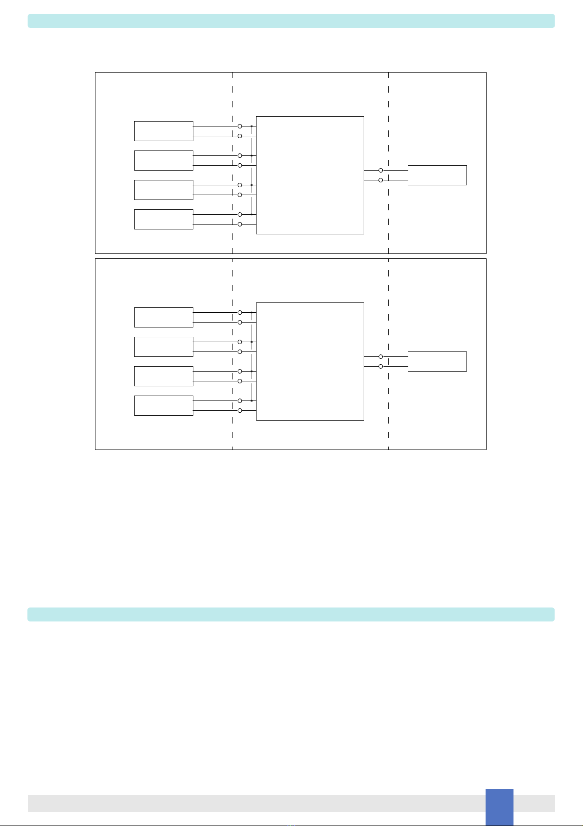
Each of the four independent channels provides an output (see the output diagram on data sheet for details of voltage and current to the load) in Hazardous Area/Hazardous Locations to
drive Intrinsically Safe loads, typically 4-20 mA transmitter for multiplexer unit or local indication without signal repetition. Presence of supply power is displayed by a green signaling LED.
Unclassified Locations or
Hazardous (Classified) Locations
Class I, Division 2, Groups A, B, C, D, T-Code T4
Class I, Zone 2, Group IIC, IIB, IIA, T-Code T4
FM Approved under Entity Concept,
or third party approval
Hazardous (Classified) Locations
Class I, Division 1, Groups A, B, C, D
Class II, Division 1, Groups E, F, G
Class III, Division 1
Class I, Zone 0, Group IIC, IIB, IIA
Intrinsically
Safe Equipment
Must not use or generate
more than 250 Vrms or Vdc
Unclassified Locations
Hazardous (Classified) Locations
Class I, Division 2, Groups A, B, C, D
Class II, Division 2, Groups E, F, G
Class III, Division 2
Class I, Zone 2, Group IIC, IIB, IIA
13
14
+
-
-
+
Power Supply
3
4
16
15
-
+
Intrinsically
Safe Equipment
10
9
-
+
Intrinsically
Safe Equipment
12
11
-
+
Intrinsically
Safe Equipment
PSD1001 Associated Apparatus
FM Approved
under Entity Concept
and non-incendive field wiring
Non-incendive
Equipment
FM Approved under non-incendive field
wiring (permitted only for US installations),
or third party approval
11
12
9
10
15
16
14
13
Unclassified Locations or
Hazardous (Classified) Locations
Class I, Division 2, Groups A, B, C, D, T-Code T4
Class I, Zone 2, Group IIC, IIB, IIA, T-Code T4
+
-
+
-
-
+
-
+
PSD1001 Associated Apparatus
FM Approved
under Entity Concept
and non-incendive field wiring
Power Supply
3+
4-
Must not use or generate
more than 250 Vrms or Vdc
Unclassified Locations
Non-incendive
Equipment
Non-incendive
Equipment
Non-incendive
Equipment