EMA BlueTraker LRIT User manual

BlueTraker®LRIT
and LRIT Arctic
Mechanical and Electrical Installation Manual
Document type: Public
Document ID: 11953
Revision No.: 1.3

Page 2 of 20
Document Information
Document Title :
BlueTraker®LRIT and LRIT Arctic
Mechanical and Electrical Installation Manual
Document Revision :
1.3
Document class :
Technical documentation
Released (yyyy-mm-dd) :
2019-04-10
Author :
Jakob Žugelj
Document ID :
11953
Document status :
Released

Page 3 of 20
1Contents
Table of content:
1Contents ........................................................................................................................................3
2BlueTraker®LRIT and LRIT Arctic terminal - Technical specifications ...................................................4
2.1 Specifications .............................................................................................................................4
3Installation overview .......................................................................................................................6
4Marking and identification ................................................................................................................7
5Installation of BlueTraker®LRIT terminal ..........................................................................................8
5.1 Package contents........................................................................................................................8
5.2 Tools needed for the installation...................................................................................................8
5.3 Prerequisites and requirements ....................................................................................................9
5.4 Select proper choice of terminal mounting position ......................................................................10
5.5 UniMount bracketry kit ..............................................................................................................12
5.5.1 UniMount bracketry kit assembly contents...........................................................................12
5.5.2 Installation of UniMount bracketry kit..................................................................................12
5.5.3 Installation of BlueTraker®LRIT terminal onto the UniMount bracketry kit .............................12
6Main Cable Set - Installation Guideline ............................................................................................13
7Finalizing the installation................................................................................................................15
8Status LED description...................................................................................................................15
9BlueTraker®LRIT Activation...........................................................................................................16
10 Transfer of Flag State....................................................................................................................16
11 User controls ................................................................................................................................17
12 Disposal .......................................................................................................................................17
13 Disclaimer ....................................................................................................................................17
14 Regulatory Information..................................................................................................................17
15 EC Declaration of Conformity..........................................................................................................18
16 GL Type Approval..........................................................................................................................19
17 U.S. Coast Guard Certificate of Approval..........................................................................................20
Table of figures:
Figure 1: Location of markings on the top side of BlueTraker®LRIT terminal ......................................... 7
Figure 2: Location of markings on the bottom side of BlueTraker®LRIT terminal.................................... 7
Figure 3: Calculation of maximum length of Main Cable Set .................................................................. 9
Figure 4: Proper choice of BlueTraker®LRIT terminal mounting position...............................................11
Figure 5: Improper choice of BlueTraker®LRIT terminal mounting position in relation to other RF
equipment.......................................................................................................................................11
Figure 6: Improper choice of BlueTraker®LRIT terminal mounting position in relation to RADAR ............11
Figure 7: UniMount bracketry kit installation diagram ..........................................................................12
Figure 8: BlueTraker®LRIT installation onto the UniMount bracketry kit ...............................................12
Figure 9: Main Cable Set...................................................................................................................13
Figure 10: BlueTraker®LRIT wiring diagram ......................................................................................14
Figure 11: Status LED is marked by red arrow ....................................................................................15

Page 4 of 20
2BlueTraker®LRIT and LRIT Arctic terminal -
Technical specifications
BlueTraker®LRIT is a dedicated device for Long Range Identification and Tracking of vessels at sea
anytime, anywhere. The BlueTraker®LRIT comes in two versions:
-the standard version (BlueTraker®LRIT; P/N: 08567),
-The Arctic version, which is capable of starting up and operation in environmental temperatures
down to -50°C (BlueTraker®LRIT Arctic; P/N: 09204).
For all the differences between BlueTraker®LRIT and BlueTraker®LRIT Arctic, please see the
tables on pages 4 and 5. In the following chapters BlueTraker®LRIT Arctic will be mentioned
only where there are differences between the two terminals. If there are no differences, only
BlueTraker®LRIT will be mentioned.
BlueTraker®LRIT Arctic is the only LRIT solution for Sea Area A4 capable of reliable operation at all times
in all areas and all weather conditions. The BlueTraker®LRIT and BlueTraker®LRIT Arctic are designed
for more than 10 years of reliable and maintenance-free operation.
2.1 Specifications
Functionality:
BlueTraker®LRIT terminal power supply protection:
oOvercurrent protection
oOvervoltage protection
oReverse polarity protection
oLevel 3 ESD protection
Integrated Antennas:
oGPS/GLONASS
oIridium
Double-shell housing:
oWhite color outer shell, resistant to UV sun radiation.
Installation site:
oOn pole
oRail
oFlat surface
Optional mounting accessories:
oUniMount bracketry kit
Absolute maximum ratings
POWER SUPPLY
PARAMETER
Minimum
Maximum
Input voltage
-36 VDC
150 VDC
Short circuit current (@ -25°C)
-
2,2 A
Short circuit current (@ +55°C)
-
1 A
- Not applicable.

Page 5 of 20
Technical specifications
POWER SUPPLY
PARAMETER
Minimum
Nominal/Typical
Maximum
Operating voltage range
8 VDC
(1)
12/24 VDC
36 VDC
(1)
Operating voltage range for Arctic kit option
21,6 VDC
(1)
24 VDC
36 VDC
(1)
Operating terminal power supply current
(Power supply voltage = 8 VDC, Ambient Temperature = 23 °C)
-
-
0,7A
Operating terminal power supply current for Arctic kit
option
(Power supply voltage = 21 VDC, Ambient Temperature = -25 °C
-
-
0,83 A
Power supply cable outside diameter
5,35 mm
5,6 mm
5,85 mm
Power supply cable conductor diameter
-
0,75 mm2
-
IRIDIUM SBD MODEM SPECIFICATIONS
Frequency range
1616 MHz to 1626,5 MHz (L band)
GPS/GLONASS RECEIVER SPECIFICATIONS
Frequency
1575,42 MHz (L1 band)
Sensitivity –Tracking
-167dBm
Sensitivity –Navigation
-157dBm
No of channels
33 Tracking / 99 Acquisition
PART DIMENSIONS:
BlueTraker®LRIT terminal (W x L x H)
200 mm x 200 mm x 70 mm
MainCableSet11 3W 50m –when coiled (W x L x H)
250 mm x 300 mm x 70 mm
UniMount (W x L x H)
250 mm x 150 mm x 80 mm
Package (W x L x H)
370 mm x 270 mm x 190 mm
WEIGHT:
BlueTraker®LRIT terminal
1,1 Kg
MainCableSet11 3W 50m
2,5 Kg
UniMount
1,1 Kg
Package
4,9 Kg
ENVIRONMENTAL:
PARAMETER
Minimum
Maximum
Operational temperature range
-25 °C
+55 °C
Operational temperature range for Arctic kit option
-50 °C
+55 °C
Storage temperature range
-25 °C
+70 °C
Humidity
10 % RH
100 % RH
IP level of protection
IP68 (to depth of 6 m, duration 1 hour), IP69K
LEGISLATION:
PARAMETER
Document
Type approved by Classification Society
Certificate number: 60 464-09 HH
U.S. Coast Guard Approved
Certificate number: 165.207/5/0
(1) Depending on the Main Cable Set length. For additional info please contact your nearest EMA
representative.
- Not applicable.

Page 6 of 20
3Installation overview
During the installation of BlueTraker®LRIT, please follow the following steps:
Step 1
Install the BlueTraker®LRIT terminal in accordance with BlueTraker®LRIT Mechanical and Electrical
Installation Manual. Follow the chapter 5 Installation of BlueTraker®LRIT terminal on page 8.
Step 2
Immediately after installation complete the attached BlueTraker®LRIT Response Form. Note there are
two tabs, one already filled by EMA about your terminal and one for installation/vessel details. Please fill
up second tab and send the BlueTraker®LRIT Response Form to EMA (by e-mail, fax…).
Step 3
Upon reception of the BlueTraker®LRIT Response Form, EMA will check that your BlueTraker®LRIT is
working properly and run a free pre-conformance test. You will be informed about BlueTraker®LRIT
functionality and test results.
If pre-conformance test fails, you will be advised what needs to be done to make the device start working
properly. Also, re-check the installation and please notify us about the cause of the problem when it is
identified.
Step 4
After the pre-conformance test passes we will release BlueTraker®LRIT transponder’s IMEI and you will
be instructed to contact the correct LRIT Conformance Testing ASP and fill up and send them the proper
CTR test form request and payment. Usually you will be able to request a CTR on the internet. If you
order from EMA CT Codes (for Pole Star or Fulcrum) your procedure for getting CTR (Conformance Test
Report) will be much easier.
The world’s major Testing ASP’s are:
Pole Star: www.lrit.com
Fulcrum: www.fulcrum-maritime.com
CLS: www.lrit.fr
Information Technology Services: www.sirmspa.com
Transas: www.lritservice.com

Page 7 of 20
4Marking and identification
Markings and identification are applied to most significant parts of BlueTraker®LRIT. This chapter
describes markings and identification of each significant part of BlueTraker®LRIT.
Since it is impractical to have every component marked, only significant parts of BlueTraker®LRIT are
marked. Most of these markings are located on the BlueTraker®LRIT terminal (see Figure 1 and Figure
2). These identify the manufacturer, unit name, model, part number, and serial number.
Figure 1: Location of markings on the top side of BlueTraker®LRIT terminal
Figure 2: Location of markings on the bottom side of BlueTraker®LRIT terminal

Page 8 of 20
5Installation of BlueTraker®LRIT terminal
WARNING:
There are no user serviceable parts inside BlueTraker® LRIT!
The installation has to be done by authorized personnel only!
5.1 Package contents
•BlueTraker®LRIT satellite communications terminal (PN: 08567) or BlueTraker®LRIT
Arctic satellite communications terminal (PN: 09204)
•UniMount (PN: 08165) terminal mounting bracket with assembly components
•Main Cable Set (PN: 12257)
•BlueTraker®LRIT and BlueTraker®LRIT Arctic Mechanical and Electrical Installation
Manual (this document, PN: 11953)
•BlueTraker®LRIT Response Form
IMPORTANT:
Verify that all listed items are included and that nothing has been
damaged in transit.
5.2 Tools needed for the installation
Besides BlueTraker®LRIT package, you will need some additional tools and supplies (the tools listed are a
recommendation –please note that you may need additional tools, depending on your particular
installation):
•Ladder/elevator (to access the mounting position),
•Personal safety equipment (Safety belt and rope).
IMPORTANT:
The listed equipment covers typical installations. You may require
additional equipment. Select the appropriate tools and equipment for
your particular installation requirements.

Page 9 of 20
5.3 Prerequisites and requirements
•Ensure that you have access to vessel power supply and grounding.
•Select the locations for installing the BlueTraker®LRIT terminal (for more information refer to
chapter “Select proper choice of terminal mounting position” on page 10).
•Select the path for running the Main Cable Set. Cables must be secured and supported at
regular intervals and protected against physical damage.
BlueTraker®LRIT terminal is designed to operate at power supply voltages down to 8 VDC (or 21 VDC in case of
BlueTraker®LRIT Arctic). Because the terminal draws up to 0,7 ADC current there is a voltage drop present on
the Main Cable Set. This voltage drop needs to be compensated with higher power supply voltage or the total
length of a Main Cable Set needs to be reduced.
Figure 3: Calculation of maximum length of Main Cable Set
To calculate the maximum Main Cable Set length for a known minimum vessel power supply voltage, use the
following formula:
𝑙 =
𝑈𝑉𝐸𝑆𝑆𝐸𝐿 − 𝑈𝐵𝑇
𝐼𝐵𝑇 ∗ 2 ∗ 𝑅𝑀𝐶𝑆
To calculate the minimum vessel power supply voltage for a known maximum Main Cable Set length, use the
following formula:
𝑈𝑉𝐸𝑆𝑆𝐸𝐿 = 𝑈𝐵𝑇 + 2 ∗ 𝑅𝑀𝐶𝑆 ∗ 𝐼𝐵𝑇 ∗ 𝑙
Where:
UVESSEL = minimum vessel power supply voltage
UBT = minimum BlueTraker®LRIT operational power supply voltage (see technical specifications)
IBT = maximum BlueTraker®LRIT operational current (see technical specifications)
l = maximum Main Cable Set length
RMCS = resistance of Main Cable Set’s wire per meter, which is 0,028Ω/m.

Page 10 of 20
5.4 Select proper choice of terminal mounting position
IMPORTANT:
BlueTraker®LRIT terminal requires clear sky view.
Never place anything on top of the BlueTraker®LRIT terminal.
Never place the BlueTraker®LRIT terminal inside radiation fields of other
RF equipment or other RF equipment into the BlueTraker®LRIT terminal’s
antenna radiation field.
Improper installation voids warranty!
Installation of terminal should be done with proper mounting accessories!
The good positioning of the device is the key to a successful operation –there must be no obstacles
in the area which can block Radiofrequency (RF) signals in horizontal or vertical directions.
BlueTraker®LRIT terminal contains receiving and transmitting internal antennas. For this reason,
the mounting place for the terminal is of utmost importance.
Key guidance’s which must be considered when choosing the appropriate mounting spot are:
•BlueTraker®LRIT terminal should be mounted outside any cabin and as high as possible,
•BlueTraker®LRIT terminal should be mounted horizontally,
•There aren’t supposed to be any obstacles near or over the device, which could block RF signals,
•There must be no overlapping of the RF radiation fields of the BlueTraker®LRIT terminal and other RF
equipment,
•BlueTraker®LRIT terminal must be installed at least 0,75m away from a standard magnetic compass
and 0,45m away from a steering magnetic compass,
•Mounting surface should be rigid enough to withstand mechanical vibrations - try to avoid strengthening
vibrations already present,
•Choose a suitable mounting position away from loading places, passages and out of reach from
unauthorized personnel,
•Avoid mounting near exhausts, direct heat and steam exposure,
•Recommended spots would be a rigid object like the mast.
Page 11 of 20
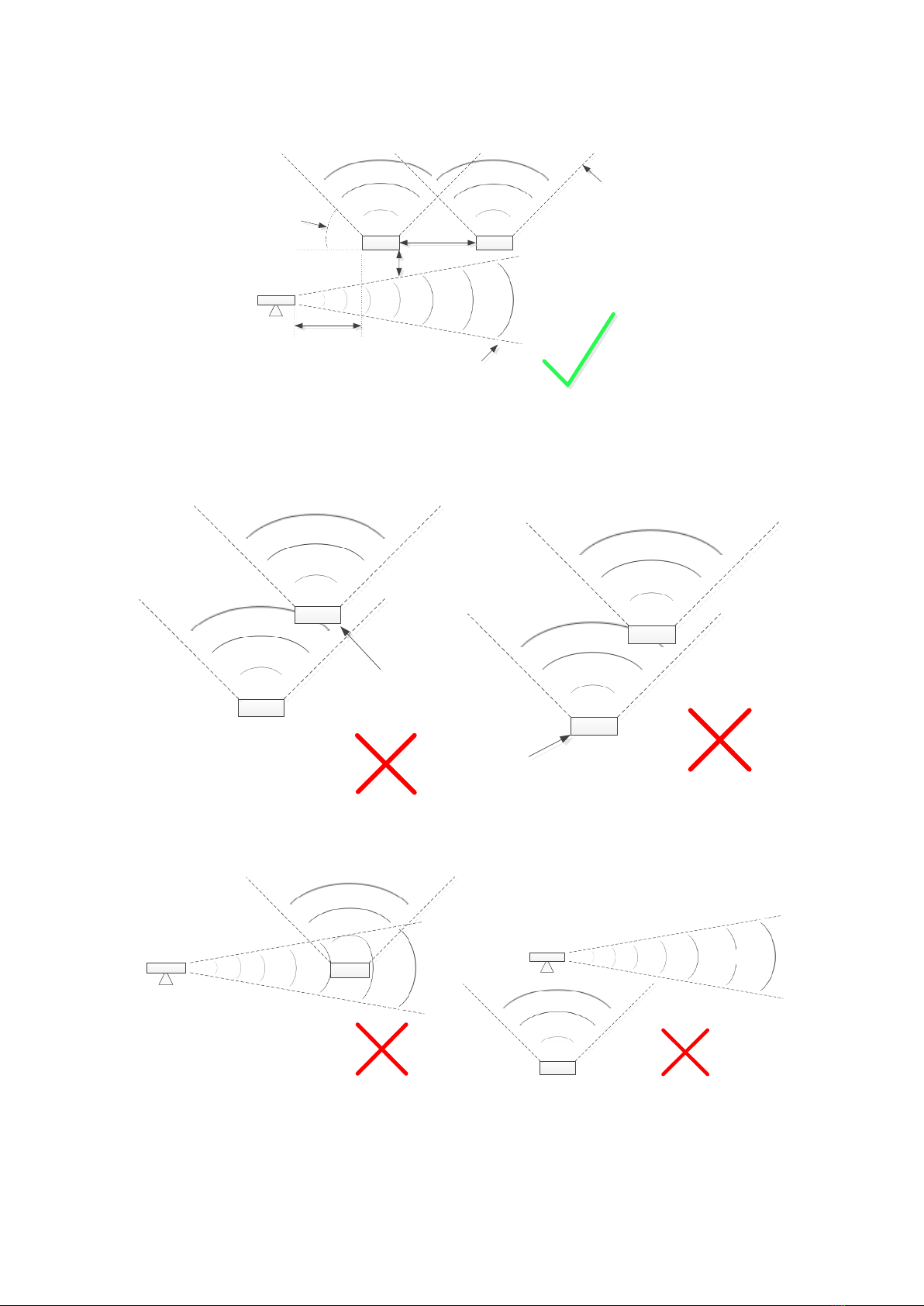
Proper choice of BlueTraker®LRIT terminal mounting position (Note: BT is short for BlueTraker):
BT
RADAR beam
min.
1m
RADAR
min. 2m
BlueTraker
antenna beam
10°- 20°
Other RF
equipment
antenna beam
min. 2m
Figure 4: Proper choice of BlueTraker®LRIT terminal mounting position
Improper choice of BlueTraker®LRIT terminal mounting position:
BT
Other RF
equipment
Other RF
equipment
BT
Figure 5: Improper choice of BlueTraker®LRIT terminal mounting position in relation to other RF equipment
RADAR BT
RADAR
BT
Figure 6: Improper choice of BlueTraker®LRIT terminal mounting position in relation to RADAR

Page 12 of 20
5.5 UniMount bracketry kit
5.5.1
UniMount bracketry kit assembly contents
UniMount bracketry kit consists of following components:
•UniMount bracket (1) PN: 10245
•UniMount clamp (2) PN: 09982
•4x M5x45mm screws for UniMount clamp (3) PN: 11741
•4x M5 wide washers for UniMount clamp (4) PN: 10005
•8x M5 self-locking nuts (5) PN: 07574
•4x M5x40mm screws for BlueTraker®VMS terminal (6) PN: 07317
•8x M5 flat washers for BlueTraker®VMS terminal (7) PN: 07576
5.5.2
Installation of UniMount bracketry kit
To install UniMount bracketry kit, use the following procedure:
1. Position the UniMount bracket (1) and UniMount clamp (2) around the rail and hold firmly in place.
2. Insert the top two M5x45mm screws (3) through the clamp and bracket holes and fix with the M5 wide
washers (4) and M5 self-locking nuts (5).
3. Insert the bottom two M5x45mm screws (3) through the clamp and bracket holes and fix with the M5
wide washers (4) and M5 self-locking nuts (5).
4. Use a spirit level to level the UniMount bracket horizontally.
5. Tighten all the screws to firmly fix the UniMount bracket to the rail.
Figure 7: UniMount bracketry kit installation diagram
5.5.3
Installation of BlueTraker®LRIT terminal onto the UniMount
bracketry kit
To install BlueTraker®LRIT terminal onto the UniMount bracketry kit, use the following procedure:
1. Place and align the BlueTraker®LRIT terminal (8) on the UniMount bracket (1).
2. Put one M5 flat washer (7) on each of the four M5x40mm screws (6).
3. Insert the four M5x40mm screws (6) with washers through the terminal and bracket holes and tighten
with the M5 flat washers (7) and M5 self-locking nuts (5).
Figure 8: BlueTraker®LRIT installation onto the UniMount bracketry kit

Page 13 of 20
6Main Cable Set - Installation Guideline
WARNING!
Installation has to be done by authorized personnel only!
For compatibility to IMO performance standard requirements, BlueTraker® LRIT must
receive power from ship’s main and emergency power supply!
For installation rules please refer to relevant IEC publication and Classification Society
rules.
Do not apply power to BlueTraker® LRIT until the Main Cable Set is properly wired,
checked and attached.
The BlueTraker®LRIT terminal connects to the ship’s electrical system via a Main Cable Set that plugs into
BlueTraker®LRIT terminal’s Main Connector and must be connected to ship’s main and emergency power supply.
For correct wiring diagram please refer to Figure 10 on page 14.
Figure 9: Main Cable Set
Run the Main Cable Set according to the following instructions of good electrical practice:
•Use appropriate mounting/fastening material to attach the cable at least every 30 cm of cable.
•Avoid running the cable near exhausts, direct heat and steam exposure, loading places, passages and
out of the reach of unauthorized personnel.
•Do not pull on the connector of the Main Cable Set
•Do not bend the Main Cable Set tighter than 70mm bending radius
•Sometimes it may be necessary to run cable through a pre-drilled hole. Use appropriate grommet and
apply marine sealant.

Page 14 of 20
Figure 10: BlueTraker®LRIT wiring diagram
COMPASS SAFETY
DISTANCE

Page 15 of 20
7Finalizing the installation
The last step in the BlueTraker®LRIT installation is to verify the operation of the terminal and to fill out and send
the BlueTraker®LRIT Response Form.
To verify the BlueTraker®LRIT system installation:
1. Turn on the power supply.
2. After 5 minutes check the status indicators sequence on the BlueTraker®LRIT terminal:
•BLUE indicator should stay lit for 2 seconds,
•Then RED indicator should stay lit for 2 second,
•Then GREEN indicator should stay lit for 2 second,
•And finally, no indicator should be lit for 2 seconds.
IMPORTANT:
After first power-up the BlueTraker®LRIT terminal starts the initialization
sequence. During this time the RED status indicator on the terminal
flashes (this may take a few minutes). After successful initialization the
indicator colors change according to the sequence mentioned above.
8Status LED description
BlueTraker® LRIT has a status LED installed on its bottom side (as shown on Figure 11).
Figure 11: Status LED is marked by red arrow

Page 16 of 20
It displays status of power supply to the unit, status of GPS/GLONASS signal and status of Iridium network
connection. Each of these three statuses is represented by one color of the LED light. Color/Status of LED
changes every 2 seconds and shows the state of the system it represents:
•RED (LIT) - normal operation, powered by electrical supply of the vessel
•RED (FLASHING) - initialization sequence in progress
•BLUE (LIT) –Connected to IRIDIUM satellite network
•BLUE (FLASHING) –IRIDIUM Satellite network not available
•GREEN (LIT) –GPS/GLONASS fix acquired
•GREEN (FLASHING) –No GPS/GLONASS fix
9BlueTraker®LRIT Activation
BlueTraker®LRIT activation procedure is described in relevant document supplied by flag state ASP.
In general ship operator should provide all the relevant info to flag state ASP. This includes, but is not limited to:
•Call sign and IMO number;
•Accurate Gross Tonnage figures;
•Sea area as indicated on the Ship Safety (Radio) Certificate;
•The communication system used for LRIT and the terminal number (i.e. Iridium IMEI number);
•Name of ship owner’s organization and flag state authority relation number.
10 Transfer of Flag State
The ship owner shall ensure that the relevant info is provided to flag state authority upon the transfer of Flag
State of a vessel. This includes, but is not limited to:
“Flag in”, in addition to the basic LRIT data (ship’s name, IMO number, call sign and MMSI):
•the effective date and time (UTC) of transfer;
•The State whose flag the ship was formally entitled to fly, if known.
“Flag out” or taken out of service:
•ship’s name;
•IMO number;
•the effective date and time of transfer, or the time of taking out of service;
•The State to which the flag of the ship will be/has been transferred, if known.

Page 17 of 20
11 User controls
There are no user controls on BlueTraker®LRIT. Flag state ASP has complete control over BlueTraker®LRIT at
all times while device is connected to ships power supply.
BlueTraker®LRIT can be set to stop sending of position reports with remote command, sent by flag state ASP!
12 Disposal
Do not dispose any electronic equipment in the domestic household waste!
Any equipment pending disposal should be returned to the manufacturer or local representative!
13 Disclaimer
Manufacturer reserves the right to make changes without further notice to the product to improve reliability,
function or design. This document and the information contained herein are the subject of copyright and
intellectual property rights under the international conventions act.
For the most recent version of this document please contact your nearest EMA distributor.
All rights reserved.
No part of this document may be reproduced, stored in a retrieval system, or transmitted in any form by any
means: electronic, mechanical or optical, in whole or in part, without the prior written permission from the
manufacturer.
14 Regulatory Information
This product is not designed for use in life support appliances, devices, or systems where malfunction of this
product or related accessories can reasonably be expected to result in personal injury or loss of life.

Page 18 of 20
15 EC Declaration of Conformity

16 GL Type Approval
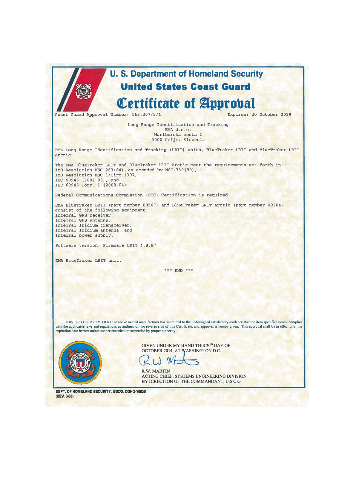
17 U.S. Coast Guard Certificate of Approval
This manual suits for next models
1
Table of contents


