EMBRON HATTELAND TECHNOLOGY HD TMB-SX1-A1 User manual
Page 1 of 5
IND100148-7 - Rev 08 - 21 Feb 2020 - Created by: 363
Hatteland Technology AS | www.hattelandtechnology.com | Enterprise no: NO974533146
28Installation
IND100078-34
Installation Procedures
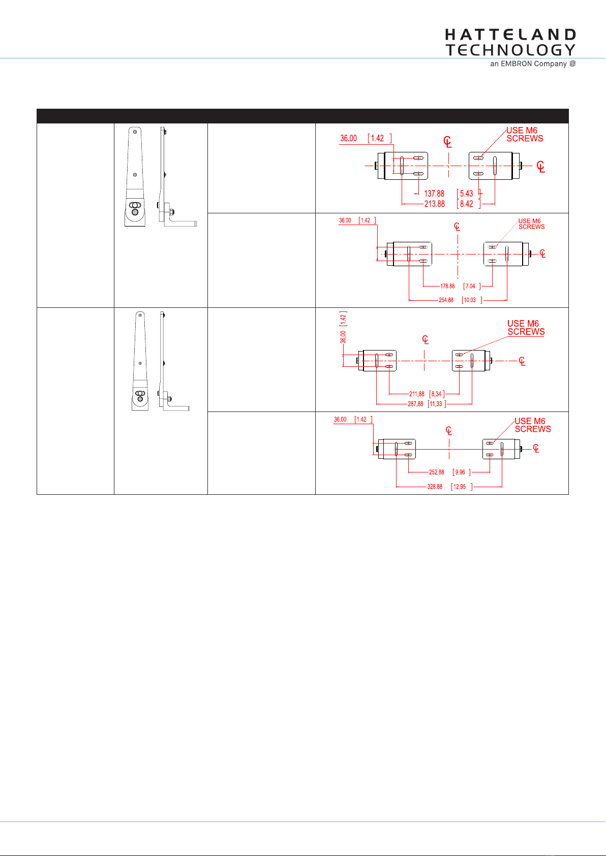
Mounting Bracket, Table / Desktop / Ceiling - 12”,15”,17”,19”
Typenumber Illustration Fits unit model “Footprint” indicates holes to drill at installation location.
HD TMB-SX1-A1 HD 12T21 MMD-xxx-Fxxx
HD 12T21 STD-xxx-Fxxx
HD 12T21 MMC-xxx-xxxx
HD 15T21 MMD-xxx-Fxxx
HD 15T21 STD-xxx-Fxxx
HD 15T21 MMC-xxx-xxxx
HD TMB-SX1-B1 HD 17T21 MMD-xxx-Fxxx
HD 17T21 STD-xxx-Fxxx
HD 17T21 MxC-xxx-xxxx
HD 19T21 MMD-xxx-Fxxx
HD 19T21 STD-xxx-Fxxx
HD 19T21 MxC-xxx-xxxx
Page 2 of 5
IND100148-7 - Rev 08 - 21 Feb 2020 - Created by: 363
Hatteland Technology AS | www.hattelandtechnology.com | Enterprise no: NO974533146
29
Installation Procedures
Installation
IND100078-34
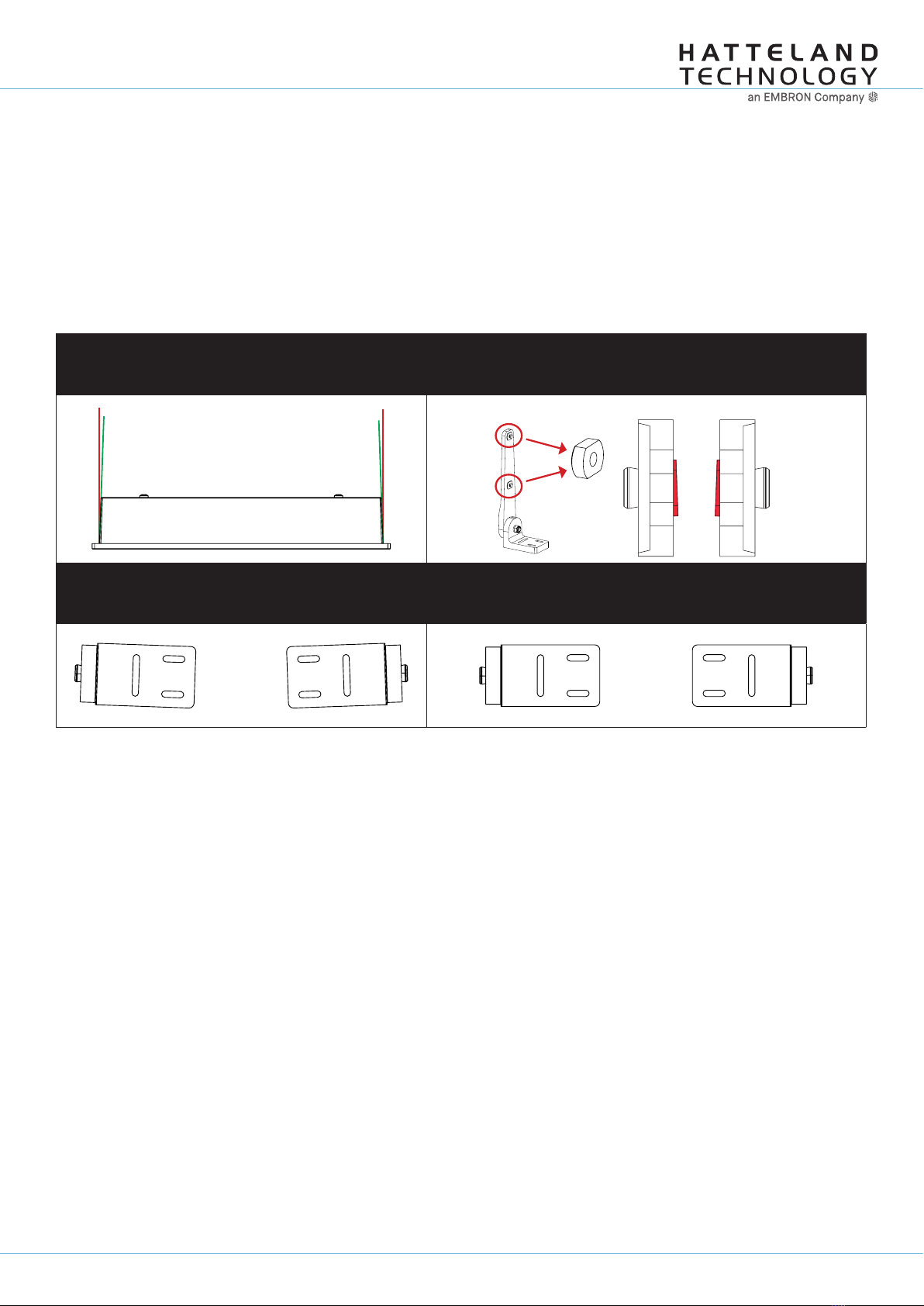
Important to know about LEFT and RIGHT brackets
Throughout the following installation procedure, it is important to understand the difference between LEFT and
RIGHT brackets. The Display and Panel Computer chassis are not 100% square boxed, but are slightly designed with
a minor narrow angled chassis towards the rear (FIG1) to allow easier “drop-in” of units into consoles. Likewise to
get a correct footprint placement of the brackets, both brackets feature a slight angled design on the oval circled cut
shaped block to compensate for this (FIG2) making LEFT and RIGHT bracket slightly different and naturally has to be
correctly mounted.
Please ensure that LEFT and RIGHT brackets are as indicated in FIG4, and not as shown in FIG3 below.
FIG 1
Red Line straight up
Green Line indicates slight angled design of chassis
FIG 2
Location of angled block,
and seen straight from top showing slight angle
LEFT BRACKET RIGHT BRACKET
FIG 3 - Seen from under bracket base
Wrong mounting of LEFT / RIGHT Brackets
Indicating footprint is incorrect
FIG 4- Seen from under bracket base
Correct mounting of LEFT / RIGHT Brackets
Indicating footprint is correct

Page 3 of 5
IND100148-7 - Rev 08 - 21 Feb 2020 - Created by: 363
Hatteland Technology AS | www.hattelandtechnology.com | Enterprise no: NO974533146
30
Installation Procedures
Installation
IND100078-34
Installation Procedure - TMB Versions
Procedure suitable for: Display (MMD/STD) and Panel Computer (MMC) Series X Generation (G1) product ranges.
19 inch model used as example in this procedure.
You need:
- M4 Unbrako® Hex Key tool (not included with delivery).
- M7 Unbrako® Hex Key tool (not included with delivery) - Needed only for alternative procedure in Step 2,3.
- M17 Open End Wrench tool (not included with delivery) - Needed only for alternative procedure in Step 2,3.
- Fasteners (6 pcs M6) for mounting complete unit onto table or desktop location (not included with delivery).
- 1 pcs of HD TMB SX1-A1 Mounting Bracket Kit (for 12 and 15 inch)
- or 1 pcs of HD TMB SX1-B1 Mounting Bracket Kit (for 17 and 19 inch)
Boxed marked with GREY color below are considered alternative procedures. In most cases, these procedures can
be ignored as suggested by factory.
Attention: A suitable pre-drilled location and knowledge of measurements for both main unit and
brackets/tilting functionality should be prepared and checked prior to mounting. Please disconnect
ALL cables before proceeding. Please review User Manual or visit www.hattelandtechnology.com
for Technical Drawings regarding measurements for both main unit and Mounting Brackets.
▼ 1: Place the unit on a dry, fl at, clean, soft surface (i.e. table)
with the glass front facing down as illustrated. Connector area
should be facing downwards from you.
▼ 2: By factory default the lower part of the bracket (Feet
Base) are tightly fastened by the center Hex Socket Bolt and
Locking Nut. Tilting can not be performed by hand. If you
need to pre-confi gure the tilt angle of the fi nal assembled
unit with brackets BEFORE you secure it into the installation
location, simply unscrew and loosen the Locking Nut (M17)
fi rst and the Hex Socket Screw (M7) as indicated below. If
there is no need to adjust the Feet Base (use recommended
factory default position of 0 degree), skip to step 4 now.
Seen from
above
Connector Area
12
▼ 3: Once loosened a bit, pull out the Tilting Lock Pin, rotate it 90° (FIG1 / FIG2) and you are now able to tilt/rotate the Feet
Base by hand (FIG3). Once the desired angle has been reached, rotate the Tilting Lock Pin 90° and lock the angle into the
nearest “click” the Locking Pin matches (FIG 1 / FIG2). Make sure both Feet Base are tilted/rotated to EXACTLY the same
angle! Secure both Hex Socket Bolts and Locking Bolt (FIG4) so they cannot move by themselves when proceeding to next
step. Use Torque Force 25Nm.
FIG1 FIG2
Locked Unlocked
FIG3 FIG4
Page 4 of 5
IND100148-7 - Rev 08 - 21 Feb 2020 - Created by: 363
Hatteland Technology AS | www.hattelandtechnology.com | Enterprise no: NO974533146
31
Installation Procedures
Installation
IND100078-34
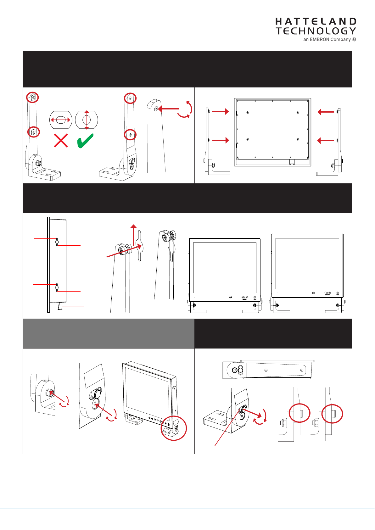
▼ 4: Inspect the inner side of both brackets and especially the
orientation of the Key Hole Plug (4 pcs). They should be shaped
as an standing “egg” to ensure proper fi tting in the Key Hole of
unit (FIG1). Note: You may have to loose the fastening screw (M5)
(FIG2) if the Key Hole Plug can not be turned by hand.
▼ 5: Notice the indication of LEFT and RIGHT. The
mounting bracket (2 pcs) is marked with respective
stickers “L” and “R” from factory. Please make sure that
LEFT bracket is positioned on LEFT side and RIGHT
bracket is positioned on the RIGHT side as shown below.
Wrong Correct Adjust
FIG2
FIG1 LEFT RIGHT
▼ 6: Ensure that both Key Hole Plugs slide into the Key Holes and goes to the upper position (factory recommended) (FIG1 and
FIG2). If they appear too tight, you may loose the Key Hole Plug screw a few turns and re-try (see previous step 4).
You can also alternatively use the lower position of Key Hole to add extra height under unit to allow cables and/or additional
installed connectors to fi t in tight installations (FIG 3 and FIG 4 shows difference gained).
FIG1
FIG2
Upper
Upper
Lower
Lower
Connectors
Lower
Upper
FIG3 FIG4
Note: If you had previously loosened the Hex Socket Bolt and
Locking Nut in Step 2-3, secure both the Hex Socket Bolt and
Locking Nut using Torque Force 25Nm. If you didn’t loose them,
proceeed to Step 8.
▼ 7: While unit is lying fl at on table, check the Tilting Lock
Pin position. These can be pulled out by hand, turned 90°
(FIG1) and turned back 90° until the Lock Pin automatically
clicks into place by a spring (FIG2).
FIG1
FIG2
Locked Unlocked
Glass Facing Up
Page 5 of 5
IND100148-7 - Rev 08 - 21 Feb 2020 - Created by: 363
Hatteland Technology AS | www.hattelandtechnology.com | Enterprise no: NO974533146
32
Installation Procedures
Installation
IND100078-34
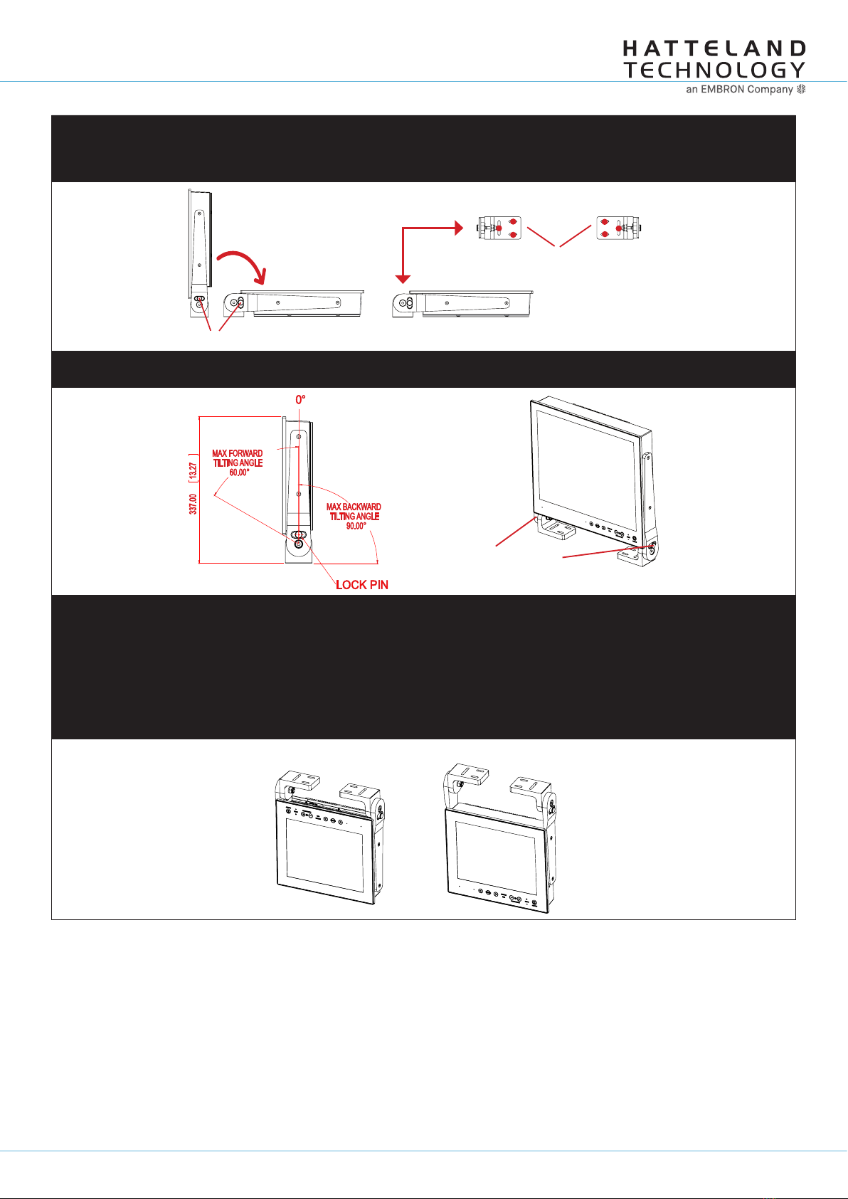
▼ 8: You may now mount the unit onto your desired location. It is advised that you unlock the Lock Pin (as shown in step 5), tilt
the unit 90 degrees backwards (FIG1) and properly fasten the bracket base into location (FIG2). NB! Be careful not to break
or scratch the edge of the front glass!
You may notice that it is now possible to tilt the unit while Base Feets are fasten as the
added weight of unit will help the momentum (see Step 2, “Tilting can not be performed by hand”).
Unlock, tilt and lock
FIG1 FIG2 Top View
Use appropriate fasteners
6 pcs x M6 needed
▼ 9: Max Forward and Backward angle shown below (FIG1). When your desired tilting position has been achieved, you need to
verify that the Tilting Lock Pin are in locking position and the unit is fi rmly attached and does not appear loose (FIG2).
FIG2
Re-check Lock Pins!
FIG1
▼ Alternative Mounting: Depending on installation needs, you may mount the complete unit in ceiling in two different ways.
Normal Position: User Controls will be upside down, cables go straight up. You may confi gure Glass Display Control™(GDC)
LED symbols to show or not, since symbols will be seen upside down.
Review https://www.hattelandtechnology.com/hubfs/pdfget/inb100018-4.htm (“Glass Display Control™ (GDC) LED & Button
operations” section).
Swapped Position: User Controls readable, cables has to bend up or go straight down, Left and Right Bracket needs to be
swapped, indicating Left Bracket on Right Side, and RIght Bracket on Left Side to ensure proper fi tting and to avoid wrong
footprint of the mounting holes of the bracket base (reference to “Important to know about LEFT and RIGHT brackets”).
Normal Position Swapped Position
This manual suits for next models
1
Table of contents
Other EMBRON TV Mount manuals


