EMC VNXe3100 User manual

2/2/11 1
EMC®VNXe3100™
Replacing a VNXe3100 Memory Module
Before you start
Before you begin the replacement procedure, make sure you have correctly identified the faulted part,
and that a replacement memory module (DIMM) is available. Refer to your EMC® VNXe™ online help
(Servicing your system > Adding or replacing faulted hardware components > Replace a faulted
hardware component) for instructions on how to identify failures, order new parts, and handle
hardware components. Also, prepare your disk processor enclosure (DPE) for service as described
below.
Preparing your disk processor enclosure for service
IMPORTANT
To protect your VNXe system from accidental data loss while you remove and replace DPE
components, open Unisphere™ and select Settings, then Service System.
• Log in with your service password.
•IntheSystem Components column, select the storage processor (A or B) associated with the
faulted component.
•UnderService Actions, select Enter Service Mode, then Execute service action.
The storage processor fault LED will flash alternating amber and blue while the SP remains in
Service Mode and is receiving active power.
Contents
This document provides instructions on the following tasks:
Task 1: Remove the storage processor (SP) assembly on page 2
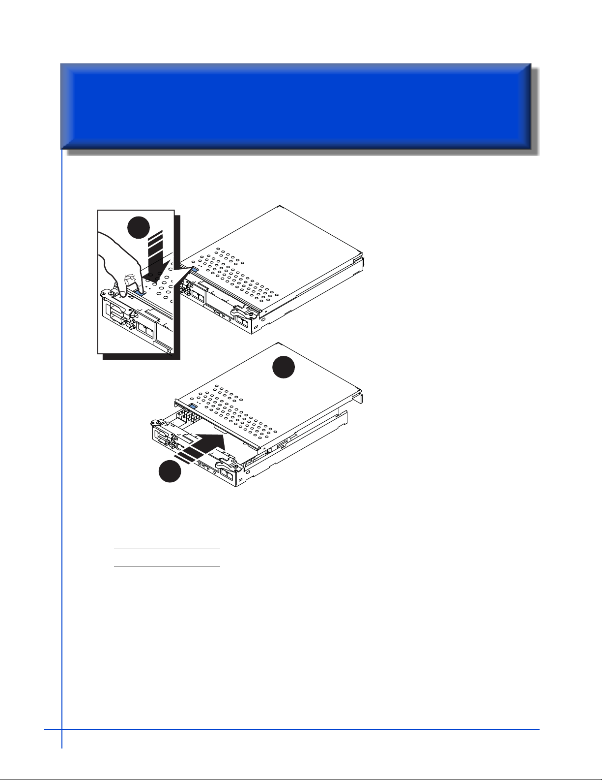
Task 2: Remove the SP assembly top cover on page 3
Task 3: Replace the memory module on page 4
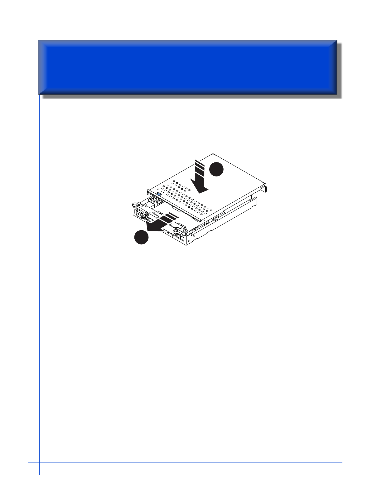
Task 4: Replace the SP top cover on page 5
Task 5: Replace the storage processor on page 6
Task 6: Reboot the storage processor on page 7
Task 7: Verify the operation of the new module on page 7
Task 8: Return the faulted memory module on page 8

Replacing a VNXe3100 Memory Module2
Task 1: Remove the storage processor (SP) assembly
The memory modules reside on the storage processor printed circuit board (motherboard), within the
storage processor assembly. To replace a memory module, you must remove the SP assembly from the
chassis, and then remove its top cover to gain access to processor board components.
Follow these steps to remove the VNXe storage processor assembly:
CAUTION
DO NOT REMOVE a storage processor while the “Unsafe to remove SP” LED is on.
The light indicates that you may interrupt a vital system or data-caching process.
If your system has a single storage processor, DO NOT REMOVE the storage
processor if the “Unsafe to remove” LED for the cache protection module is on.
1. Disconnect the network and all other cables from the back of the assembly that includes the faulted
module. Do not remove any cables from the other storage processor assembly.
Mark the cables with the port numbers from which you removed them.
2. Locate the two orange release levers on the storage processor latches.
3. Squeeze the levers to release the latches and then pull the latches outward.
4. Pull out the latches until they are fully extended and the storage processor assembly is released from
its enclosure.
5. Use the latches to partially slide the assembly from its enclosure. When the storage processor is about
half-way out of its enclosure, use both hands to support the assembly and draw it fully out of the
enclosure.
6. Place the storage processor assembly on a clean, flat, static-free work surface.
CL4682

Task 2: Remove the SP assembly top cover 3
1. Press the blue button on the cover.
2. Push the cover back 1/4 inch.
3. Lift the cover up.
4. Unpack the replacement memory module and then place it on the same clean, flat, static free work
area.
Note: Retain the packaging to return the faulted module.
2
3
1
Task 2: Remove the SP assembly top cover

Replacing a VNXe3100 Memory Module4
Remove the memory module from the storage processor, and install the replacemen:.
1. Rotate the memory module latches outward to release the module from the socket.
2. Touching only the outside edges of the memory module, pull the module directly out of the socket,
and place it on an antistatic surface.
3. Remove the replacement memory module from its antistatic bag.
4. Handling only the outside edges of the module, align the module with the socket.
Note: The socket and module are keyed to prevent incorrect alignment.
5. Firmly push the module directly into the socket.
6. The latches will snap to the closed position when the module is fully inserted in its socket.
21
3
4
DIMM 0 DIMM 1
Task 3: Replace the memory module

Task 4: Replace the SP top cover 5
Replace the canister cover:
1. Align the cover tabs with the notches in the canister.
2. Slide it forward 1/4 inch until the tab secures the cover.
2
1
Task 4: Replace the SP top cover

Replacing a VNXe3100 Memory Module6
Replace the SP assembly in the enclosure:
1. Pull out the latches on each side of the SP and make sure they stay in the open position.
2. Align the SP with the chassis opening and push it straight into the chassis.
The latches begin to close when they contact the chassis edges.
3. Close the right and left latches to fully seat the SP in the chassis.
An audible click indicates that the latches are secure.
4. Reconnect the cables to the back of the storage processor.
• Connect all cables to the same ports from which you removed them on the faulted SP assembly.
• The SP begins powering up immediately after connection to an active AC power source.
CL4687
Task 5: Replace the storage processor

Task 6: Reboot the storage processor 7
Once you have replaced the faulted memory module and returned the storage processor assembly to
the chassis, reboot the recently serviced SP to ensure that it leaves Service Mode:
1. From Unisphere, select Settings, then Service System.
2. Log in with your service password.
3. In the System Components column, select the replaced storage processor (A or B).
4. Under Service Actions, select Reboot, then Execute service action.
Note: It may take several minutes for the system to complete its reboot and return to Normal Mode.
5. Refresh your browser, or follow the on-screen instructions, to bring the software out of Service Mode
and restore full-function Unisphere.
Verify that the new memory module is recognized by your system, and operating correctly:
1. In Unisphere, click View System Health.
2. Select the storage processor in the Component list or the graphical view:
• In the Component list, the memory should be marked with a status OK icon:
• In the graphical view, the SP is highlighted green.
Note: If the system health monitor shows the replacement module as faulted, contact your service
provider.
Task 6: Reboot the storage processor
Task 7: Verify the operation of the new module

Replacing a VNXe3100 Memory Module8
Return the faulted memory module to your service provider:
1. Package the faulted part in the shipping box that contained the replacement, and seal the box.
2. From Unisphere, click Support > Need more Help? > Customer replaceable parts > Return a
customer replaceable part to enter the EMC Online Support website. The site includes detailed
instructions on how to return the faulted part.
Note: If your screen does not show the Return a customer replaceable part option, contact your
service provider for instructions on what to do next.
3. Follow the on-screen instructions. The website includes a printable return label and box pickup
information.
4. Attach the shipping label, and contact the appropriate person to pick up the faulted part.
Part number: 300-012-220 A01
Copyright © 2011 EMC Corporation. All rights reserved.
Published February, 2011
EMC believes the information in this publication is accurate as of its publication date. The information is subject to
change without notice.
THE INFORMATION IN THIS PUBLICATION IS PROVIDED “AS IS.” EMC CORPORATION MAKES NO REPRESENTATIONS OR
WARRANTIES OF ANY KIND WITH RESPECT TO THE INFORMATION IN THIS PUBLICATION, AND SPECIFICALLY DISCLAIMS
IMPLIED WARRANTIES OF MERCHANTABILITY OR FITNESS FOR A PARTICULAR PURPOSE.
Use, copying, and distribution of any EMC software described in this publication requires an applicable software license.
For the most up-to-date regulatory document for your product line, go to the Technical Documentation and Advisories
section on EMC Powerlink.
For the most up-to-date listing of EMC product names, see EMC Corporation Trademarks on EMC.com.
All other trademarks used herein are the property of their respective owners.
Task 8: Return the faulted memory module
Other manuals for VNXe3100
3
Table of contents
Other EMC Server manuals

EMC
EMC CLARiiON 300002039 User manual

EMC
EMC SVR-I1U-1208 Product manual

EMC
EMC SVR-I2U-R2312 Product manual

EMC
EMC Avamar Data Store Gen4T User manual

EMC
EMC Data Domain DD670 Use and care manual

EMC
EMC VPLEX with GeoSynchrony 4.2 Assembly instructions

EMC
EMC SVR-I2U-H2316 Product manual

EMC
EMC Celerra Installation manual

EMC
EMC Connectrix B Series Quick user guide

EMC
EMC SVR-I1U-1304 Product manual