manuals.online logo
Brands
  1. Home
  2. •
  3. Brands
  4. •
  5. EMC
  6. •
  7. Storage
  8. •
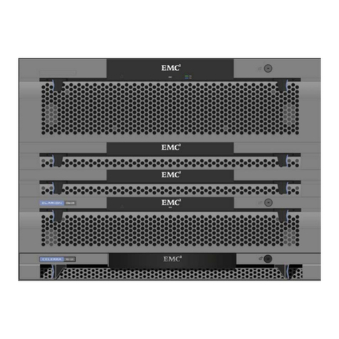
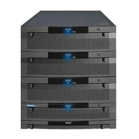
  9. EMC Celerra NS20 User instructions

EMC Celerra NS20 User instructions

Alignment
pin
Rear
Front
Adjustable rail
Alignment
pin
Right rear
Mounting rail
Screw (2)
Alignment
pin
CIP-000921
Right front
Screw
Mounting
rail
Rear
Front
Enclosure
CIP-000922
Setting Up the EMC®Celerra®NS20 System
Before You Begin
1
1
2a Install Blade Enclosure
300-004-900 Rev A01
Copyright © 2007 EMC Corporation. All rights reserved.
2c Install Control Station
2b Install Storage Processor Enclosure
Rear
Front
Enclosure
CIP-000923
Rail
catch
Screw
(2 per side)
Bezel
Indentation
to center of
the rack
2
4
3
B
A
CIP-000897
Blade enclosure
Control Station
SP ASP B
Blade 3 Blade 2
Storage processor
enclosure
B
A
Blade 3 (B 3)
SP A
B 2
CIP-000896
Blade enclosure
SP B
Storage processor
enclosure
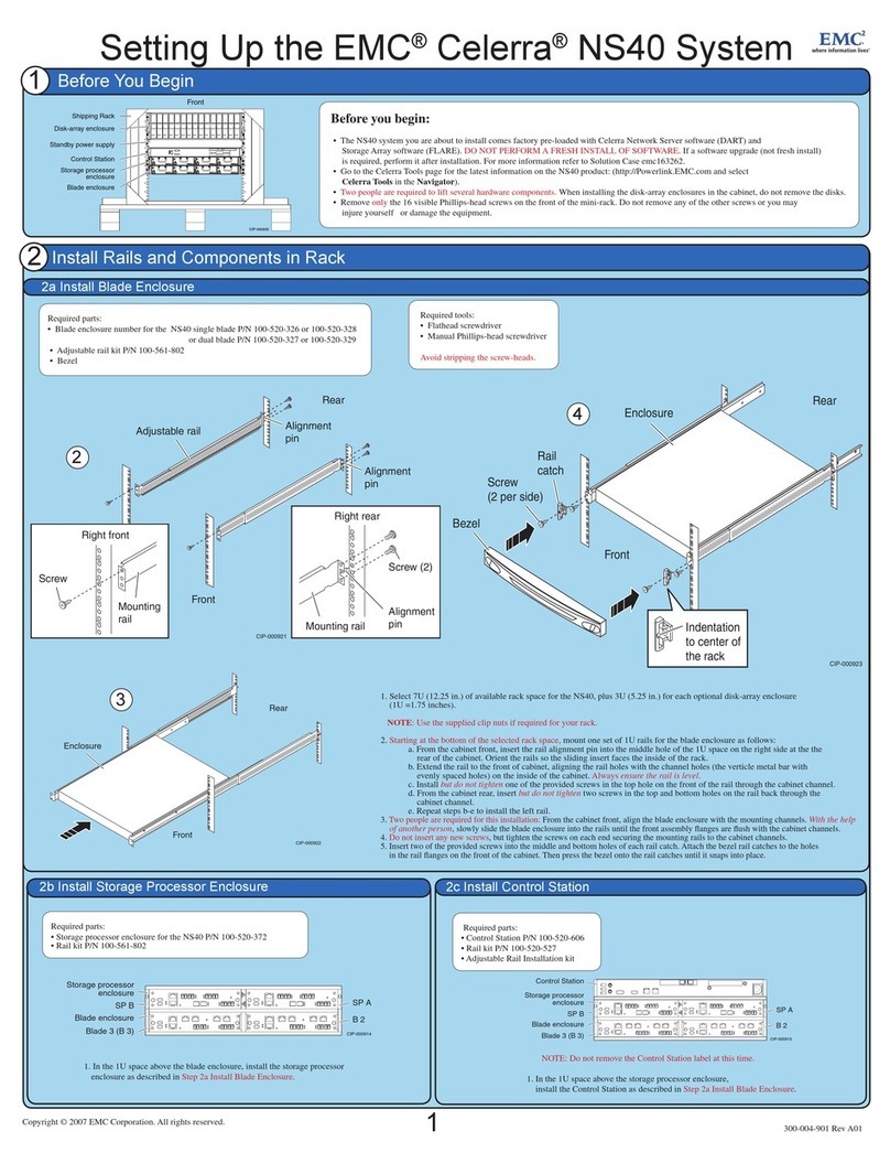
1. Select 7U (12.25 in.) of available rack space for the NS20, plus 3U (5.25 in.) for each optional disk-array enclosure
(1U =1.75 inches).
NOTE: Use the supplied clip nuts if required for your rack.
2. Starting at the bottom of the selected rack space, mount one set of 1U rails for the blade enclosure as follows:
a. From the cabinet front, insert the rail alignment pin into the middle hole of the 1U space on the right side at the
rear of the cabinet. Orient the rails so the sliding insert faces the inside of the rack.
b. Extend the rail to the front of cabinet, aligning the rail holes with the channel holes (the verticle metal bar with
evenly spaced holes) on the inside of the cabinet. Always ensure the rail is level.
c. Install but do not tighten one of the provided screws in the top hole on the front of the rail through the cabinet channel.
d. From the cabinet rear, insert but do not tighten two screws in the top and bottom holes on the rail back through the
cabinet channel.
e. Repeat steps b-e to install the left rail.
3. Two people are required for this installation: From the cabinet front, align the blade enclosure with the mounting channels.
With the help
of another person,
slowly slide the blade enclosure into the rails until the front assembly flanges are flush with the cabinet channels.
4. Do not insert any new screws, but tighten the screws on each end securing the mounting rails to the cabinet channels.
5. Insert two of the provided screws into the middle and bottom holes of each rail catch. Attach the bezel rail catches to the holes
in the rail flanges on the front of the cabinet. Then press the bezel onto the rail catches until it snaps into place.
Before you begin:
• The NS20 system you are about to install comes factory pre-loaded with Celerra Network Server software (DART) and
Storage Array software (FLARE). DO NOT PERFORM A FRESH INSTALL OF SOFTWARE. If a software upgrade (not fresh install)
is required, perform it after installation. For more information refer to Solution Case emc163261.
• Go to the Celerra Tools page for the latest information on the NS20 product: (http://Powerlink.EMC.com and select
Celerra Tools in the Navigator).
• Two people are required to lift several hardware components. When installing the disk-array enclosures in the cabinet, do not remove the disks.
• Remove only the 16 visible Phillips-head screws on the front of the mini-rack. Do not remove any of the other screws or you may injure
yourself or damage the equipment.
Required tools:
• Flathead screwdriver
• Manual Phillips-head screwdriver
Avoid stripping the screw-heads.
Required parts:
• Blade enclosure number for the NS21 single blade is P/N 100-520-336
or NS22 dual blade is P/N 100-520-334
• Adjustable rail kit P/N 100-561-802
• Bezel
Required parts:
• Storage processor enclosure P/N 100-520-622 or P/N 100-520-623
• Rail kit P/N 100-561-802
1. In the 1U space above the blade enclosure, install the storage processor
enclosure as described in Step 2a Install Blade Enclosure.
Required parts:
• Control Station P/N 100-520-606
• Rail kit P/N 100-520-527
• Adjustable Rail Installation kit
NOTE: Do not remove the Control Station label at this time.
1. In the 1U space above the storage processor enclosure,
install the Control Station as described in Step 2a Install Blade Enclosure.
LAN1
LAN2
Front
CIP-000935a
Disk-array enclosure
Standby power supply
Control Station
Storage processor
enclosure
Blade enclosure
Shipping Rack
Install Rails and Components in Rack
2
Install Rails and Components in Rack (continued)
2
Alignment pins
Adjustable rail
Right rear
Screw (2)
Alignment
pin (2)
Mounting
rail
Right front
Mounting
rail
Screw (2)
use middle
two holes
2e Install Disk-Array Enclosures
B
A
Standby power
supply (SPS)
CIP-000898
Blade enclosure
Control Station
SP A
SP B
Blade 3 Blade 2
Storage processor
enclosure
2d Install Standby Power Supply
!!
!!
!
EXP PRI
EXPPRI
#
!
EXP PRI
EXPPRI
#
A
B
B
A
Standby power
supply (SPS)
Blade 3 Blade 2
Disk-array enclosure
CIP-000899
Blade enclosure
SP ASP B
Control Station
Storage processor
enclosure
CIP-000875
Screw (2)
Screw (2)
Front
Rear
Rear
Front
CIP-000874
Tabs
Rear
Notches
Tabs
Notches
2
1. Above the Control Station rails, mount one set of 1U rails for the standby power supply (SPS),
as described in Step 2b Install Blade Enclosure.
2. With the help of another person, from the front of the cabinet, slide the SPS assembly into the 1U
space tray above the Control Station, aligning the tray with the channels on the mounting rails.
3. Use one Phillips-head M5 x 16 mm screw to secure a rail catch to each front channel.
The catches include small alignment bumps for correct orientation.
4. Press the bezel onto the rail catches at the front of the cabinet until it snaps into place.
NOTE: Use the supplied clip nuts if required for your rack.
1. Above the standby power supply, mount one set of 3U rails for the disk-array enclosure as follows:
a. Locate the rail with “R” stamped on one short side. From the cabinet front, insert this rail into the right side of the selected 3U space.
Insert the alignment pin into the hole on the inside of the rear cabinet rail.
b. Extend the rail to the front of the cabinet, aligning the rail holes with the holes on the inside of the cabinet. Make sure the rail is level.
c. Install but do not tighten two of the provided screws into the middle holes at the front of the rail.
d. Repeat steps a-d on the left side of the cabinet with the rail stamped “L.”
e. From the rear of the cabinet, use two screws to loosely secure each rail to the rear cabinet channel.
f. Tighten the four front screws on the rails. While tightening, push the rails outward to allow flexibility when inserting the enclosure.
NOTE: Do not remove the disks from the disk-array enclosure during installation.
2. With the help of another person, lift the disk-array enclosure and from the front of the cabinet insert it into the rails.
Slide it back until the notches at the back of the enclosure insert into the tabs on the back of each rail and tighten all screws on each rail.
3. Secure the enclosure front to the cabinet’s front vertical channels using four provided screws (two per side).
4. From the front of the cabinet, press the front bezel onto the rail catch until it snaps into place, then lock the bezel with the key.
5. Repeat this procedure for each optional disk-array enclosure.
Required parts:
• Standby power supply (SPS).
• Adjustable rail kit P/N 100-561-816
• Adjustable rail installation kit with Phillips-head screws
Required parts:
• Disk-array enclosure P/N 100-561-622
• Rail kit P/N 100-560-184
• Adjustable rail installation kit with Phillips-head screws
Rail
catch CIP-000937
Front
Rear
Rail
catch
Rear
Front
SPS
CIP-000939
1
3
4
2
23
Connect Cables
3
3
!!
!!
!
EXP PRI
EXPPRI
#
!
EXP PRI
EXPPRI
#
A
B
B
A
Blade enclosure
Blade 3
SP A
Blade 2
CIP-000892
SP B
Standby power supply (SPS)
Disk-array enclosure
Control Station
Storage processor
enclosure
B
A
Blade enclosure
Blade 3
SP B
SP A
Blade 2
Control Station
CIP-000902
S
tandby power
supply (SPS)
Storage processor
enclosure
S
tandby power
supply (SPS)
SP B
Control Station
Blade 2
CIP-000901
B
A
Blade enclosure
SP A
Storage processor
enclosure
NS20 FC
-Cable 1: <->
- Cable 2: <->
- Cable 3: <->
- Cable 4: <->
Blade 2 BE0
Blade 2 BE1
Blade 3 BE0
Blade 3 BE1
SP A 2Fibre
SP B 2Fibre
SP A 3Fibre
SP B 3Fibre
Required cables:
• Three cables for a single blade conguration
• Four cables for a dual blade conguration
Required cables:
• Two or four optical cables. Single blade NS20 or NS20FC systems only use two cables (cable 1 and 2).
Refer to the Sales Order to determine the number of blades.
If there is a model NS21C-A or NS21C-A -FD on the Sales Order, you are installing a single blade system.
If there is a model NS22C-A or NS22C-A -FD on the Sales Order, you are installing a dual blade system.
Dual Blade NS20/NS20FC
- Cable 1: <->
- Cable 2: <->
- Cable 3: <->
- Cable 4: <->
CS B
CS A
Blade 2
Blade 3
SP
A
SP B
Blade 3
Blade 2
NS20
-Cable 1: <->
- Cable 2: <->
- Cable 3: <->
- Cable 4: <->
Blade 2 BE0
Blade 2 BE1
Blade 3 BE0
Blade 3 BE1
SP A 0Fibre
SP B 0Fibre
SP A 1Fibre
SP B 1Fibre
Single Blade NS20/NS20FC
- Cable 1: <->
- Cable 2: <->
- Cable 3: <->
CS BSP B
Blade 2
CS A
Blade 2 SP
A
Required cables:
• SPS serial cable
- Cable 1: <->
• One modem cable:
• One telephone line (customer provided)
SP A
SPS A
CS
!!
!!
!
EXP PRI
EXPPRI
#
!
EXP PRI
EXPPRI
#
A
B
B
A
Standby power
supply (SPS)
Disk-array enclosure
SP A
CIP-000940
Storage processor
enclosure
Blade enclosure
Control Station
To external
phone line
Blade 3 Blade 2
SP B
Modem
CIP-000945
SPS B SPS A
Blade 3 Blade 2
SP ASP B
CS
LCC B
LCC A
Disk-array
enclosure
Standby power
supply (SPS)
Control Station
Storage processor
enclosure
Blade enclosure
BE 0
BE 0
Blade 2
Component Port
Cable label key
Blade 2
Required cables:
Two cables with SFP-to-HSSDC2 connectors
- Cable 1: <->
- Cable 2: <->
a. In DAE port LCC A PRI, orient the thumb clip down and insert until you hear a click.
b. In DAE port LCC B PRI, orient the thumb clip up and insert until you hear a click.
SP B BE0
SP A BE0
LCC B PRI
LCC A PRI
!!
!!
!
EXP PRI
EXPPRI
#
!
EXP PRI
EXPPRI
#
A
B
B
A
CIP-000936
Blade enclosure
SP B
Blade 3 Blade 2
Standby power supply (SPS)
Control Station
SP A
Storage processor
enclosure
Disk-array enclosure
SFP
connector
HSSDC2
connector
PRI B connector
Pull/
release tab
PRI A
HSSDC2
connector
SFP
connector
Pull/
release tab
Note: The EXP ports
are not used
!
EXP PRI
EXPPRI
#
!
EXP PRI
EXPPRI
#
EXP
EXP
PRI B
PRI A
NOTE: Use Navisphere Service Taskbar for installing and cabling any additional disk-array
enclosures after completing the Celerra Startup Assistant.
3c Serial Cables
3b Disk-array Enclosure Fibre Channel Cables
!!
!!
!
EXP PRI
EXPPRI
#
!
EXP PRI
EXPPRI
#
A
B
B
A
Blade enclosure
Blade 3
SP A
Blade 2
CIP-000891
Storage processor
enclosure
SP B
Standby power supply (SPS)
Disk-array enclosure
Control Station
3d Private LAN Cables
3a Blade Fibre Channel Cables
Use Celerra Startup Assistant
4
Powering Down Your Celerra NS20
3e External Network Cables
1. If no components other than the NS20 are in the cabinet, turn off the cabinet circuit breakers.
Otherwise leave them on.
2. Turn off your standby power supply (SPS) power switch.
3. Connect the disk-array enclosure power supply A to the SPS A power distribution panel (PDP).
4. Connect the disk-array enclosure power supply B to the left PDP.
5. Connect SPS A to the right PDP.
6. Connect storage processor enclosure A to SPS A.
7. Connect storage processor enclosure B to the left PDP.
8. Connect the power cable from the right side of the Control Station to the right PDP.
9. Connect the two 240-volt AC power cables from the cabinet to your power outlets. If possible,
connect each cable to a different circuit.
10. Turn on all circuit breakers on each of the cabinet’s power strips.
11. Turn on the SPS power switch.
12. Connect blade enclosure A to the right PDP.
13. Connect blade enclosure B to the left PDP.
14. Verify each component has power (LED illuminated). After a few minutes, each component should
have a green LED, except for the storage processor enclosure. The storage processor enclosure
powers up and is fully booted within a few minutes. The enclosure warning light will not extinguish
until the SPS battery is fully charged. This may take 15 minutes.
MGMT
1. Remove the tear away label on the front of the Control Station. You need this for the Celerra Startup Assistant.
2. Insert the Celerra Network Server Applications and Tools CD, into the client computer. EMC Product Installation window opens.
3. Click Celerra Startup Assistant and use the InstallShield to install the Celerra Startup Assistant on the client computer.
4. Double-click the Celerra Startup Assistant shortcut on the desktop or go to C:\ProgramFiles\EMC\CSA\startup\launch.bat to run the
Celerra Startup Assistant. The Celerra Startup Assistant guides you through the remaining steps.
Note: This system must be registered before the client can receive service. If the registration is not done as part of the CSA,
the customer may use the registration wizard to register the system. Go to C:\ProgramFiles\EMC\RegWiz\Register.bat
5. After the Celerra Startup Assistant
nishes with the basic installation, use the Celerra Manager to create a customized conguration of the
Celerra NS20 system.
Refer to
http://Powerlink.EMC.com (select Celerra Tools in the Navigator and select NS20 Integrated >Installation Overview)
for completing your installation.
Required parts:
•
Celerra Network Server Applications and Tools CD
• Windows-based client computer on the same subnet (customer network) as the NS20 management Control Station. You must have
100 MB of free space on the client PC. The client computer should have access to the Internet.
1. Do the following before you power down the Celerra NS20:
a. Notify all users of the planned powerdown several days in advance when possible.
b. Inhibit all logins and notify all users several minutes in advance of the impending powerdown.
c. Log out all users.
2. Log in to the Control Station as root, using a Telnet or SSH session. To perform a planned powerdown,
you must be within close proximity to the server.
3. To halt the Celerra server, type:
# /nasmcd/sbin/nas_halt now
ARE YOU SURE YOU WANT TO CONTINUE? [ yes or no ] :
# yes
Sending the halt signal to the Master Control Daemon...: Done
.
.
Halting system...
flushing ide devices: hda hdd
Power down.
It can take as long as 20 minutes to halt the server, depending on the number of blades and
the size of the database.
Wait until the command completes before continuing.
4. Disconnect the blade enclosure power cords from the power distribution units (PDUs).
5. Turn off (0 position) the power switch on the standby power supplies (SPSs) and wait at least 1 minute to
allow the storage system to write its cache to disk.
Make sure the supply’s power indicator is off before continuing.
6. Disconnect the DAE3P power cords from the PDU.
7. If no components other than the NS20 are in the cabinet, turn off the cabinet circuit breakers.
Otherwise leave them on.
ON
I
OFF
O
ON
I
OFF
O
ON
I
OFF
O
ON
I
OFF
O
!!
!!
!
EXP PRI
EXPPRI
#
!
EXP PRI
EXPPRI
#
A
B
B
A
Standby power
supply (SPS)
Blade 3 Blade 2
Control Station
Storage
processor
enclosure
SP B
Blade
enclosure
SP A
Disk-array
enclosure
CIP-000941
PDP
ON
I
OFF
O
!!
#
!
EXP PRI
EXPPRI
Required cables:
• Ethernet cable:
• Two copper Ethernet cables (customer-provided)
NOTE: Attach customer provided Ethernet cables from customer
external LAN to blade public (cge) ports.
MGMT
!
!
!!
!
EXP PRI
EXPPRI
#
!
EXP PRI
EXPPRI
#
A
B
Standby power supply (SPS)
Disk-array enclosure
SP A
CIP-000895
Blade enclosure
SP B
Control Station
Blade 3 Blade 2
To public LAN
To public LAN
To public LAN MGMT
cge0 cge1 cge2 cge3
Storage processor
enclosure
CIP-000900
ON
I
OFF
O
ON
I
OFF
O
ON
I
OFF
O
ON
I
OFF
O
ON
I
OFF
O
ON
I
OFF
O
!!
!!
!
EXP PRI
EXPPRI
#
!
EXP PRI
EXPPRI
#
A
B
!!
!!
!
EXP PRI
EXPPRI
#
!
EXP PRI
EXPPRI
#
A
B
!!
!!
!
EXP PRI
EXPPRI
#
!
EXP PRI
EXPPRI
#
A
B
!!
!!
!
EXP PRI
EXPPRI
#
!
EXP PRI
EXPPRI
#
A
B
B
A
Standby power supply (SPS)
Blade 3
Blade 2
Control Station
Storage processor
enclosure
SP B
Blade enclosure
SP A
Disk-array enclosure
Disk-array enclosure (optional)
3f Power Cables
4

Other manuals for Celerra NS20

1

Other EMC Storage manuals

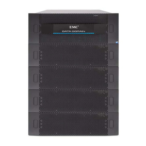
EMC FC4700 Technical manual

EMC

EMC FC4700 Technical manual

EMC DL3D 1500 Service manual

EMC

EMC DL3D 1500 Service manual

EMC CLARiiON CX4-120 User manual

EMC

EMC CLARiiON CX4-120 User manual

EMC VNXe3200 User manual

EMC

EMC VNXe3200 User manual

EMC VNX Series User manual

EMC

EMC VNX Series User manual

EMC Celerra NS20 User manual

EMC

EMC Celerra NS20 User manual

EMC VMAX 100K User manual

EMC

EMC VMAX 100K User manual

EMC DATA DOMAIN DD7200 Assembly instructions

EMC

EMC DATA DOMAIN DD7200 Assembly instructions

EMC D860 Archiver Assembly instructions

EMC

EMC D860 Archiver Assembly instructions

EMC VNX Series Owner's manual

EMC

EMC VNX Series Owner's manual

EMC Celerra User manual

EMC

EMC Celerra User manual

EMC VNX5500 User manual

EMC

EMC VNX5500 User manual

EMC DATA DOMAIN DD620 Assembly instructions

EMC

EMC DATA DOMAIN DD620 Assembly instructions

EMC EMC Unity Family User manual

EMC

EMC EMC Unity Family User manual

EMC AX4-5 User manual

EMC

EMC AX4-5 User manual

EMC DATA DOMAIN DD4200 Assembly instructions

EMC

EMC DATA DOMAIN DD4200 Assembly instructions

EMC Data Domain DD990 Assembly instructions

EMC

EMC Data Domain DD990 Assembly instructions

EMC VPLEX Assembly instructions

EMC

EMC VPLEX Assembly instructions

EMC Connectrix EC-1200 Technical manual

EMC

EMC Connectrix EC-1200 Technical manual

EMC VNX5300 Block Owner's manual

EMC

EMC VNX5300 Block Owner's manual

EMC Data Domain DD860 Assembly instructions

EMC

EMC Data Domain DD860 Assembly instructions

EMC CX700 Technical manual

EMC

EMC CX700 Technical manual

EMC EMC2 DATA DOMAIN DD660 Assembly instructions

EMC

EMC EMC2 DATA DOMAIN DD660 Assembly instructions

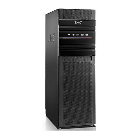
EMC Atmos Installation instructions

EMC

EMC Atmos Installation instructions

Popular Storage manuals by other brands

Huawei OceanStor T Series Quick installation guide

Huawei

Huawei OceanStor T Series Quick installation guide

Quantum DLT-V4 install guide

Quantum

Quantum DLT-V4 install guide

D-Link MediaLounge DSM-602H Quick installation guide

D-Link

D-Link MediaLounge DSM-602H Quick installation guide

Keter SOTRE-IT-OUT MIDI user manual

Keter

Keter SOTRE-IT-OUT MIDI user manual

Supermicro 6048R-E1CR24H user manual

Supermicro

Supermicro 6048R-E1CR24H user manual

HP StorageWorks Ultrium 230 User's and service guide

HP

HP StorageWorks Ultrium 230 User's and service guide

Philips FM01FD05B/00 user manual

Philips

Philips FM01FD05B/00 user manual

Buffalo JustStore Portable HD-PVU2 user manual

Buffalo

Buffalo JustStore Portable HD-PVU2 user manual

Steelcase Elective Elements Storage manual

Steelcase

Steelcase Elective Elements Storage manual

Seagate ST31000528AS - Barracuda 7200.12 1 TB 7200RPM SATA 3 GB/s 32 MB Cache Hard... datasheet

Seagate

Seagate ST31000528AS - Barracuda 7200.12 1 TB 7200RPM SATA 3 GB/s 32 MB Cache Hard... datasheet

Imation defender H200 +BIO Specifications

Imation

Imation defender H200 +BIO Specifications

Sealey GSS2323 instructions

Sealey

Sealey GSS2323 instructions

Tandberg Data RDX QuikStor quick start guide

Tandberg Data

Tandberg Data RDX QuikStor quick start guide

Seagate ST318436LW installation guide

Seagate

Seagate ST318436LW installation guide

Seagate Momentus 5400 brochure

Seagate

Seagate Momentus 5400 brochure

Seagate FreeAgent Pro datasheet

Seagate

Seagate FreeAgent Pro datasheet

Duratuf KIWI MK4C Assembly instructions

Duratuf KIWI

Duratuf KIWI MK4C Assembly instructions

Silvercrest DataBox VI 1000 User manual and service information

Silvercrest

Silvercrest DataBox VI 1000 User manual and service information

manuals.online logo
manuals.online logoBrands
  • About & Mission
  • Contact us
  • Privacy Policy
  • Terms and Conditions

Copyright 2025 Manuals.Online. All Rights Reserved.