EMC Connectrix B Series Quick user guide

EMC Corporation
Corporate Headquarters:
Hopkinton, MA 01748-9103
1
-508-435-1000
www.EMC.com
EMC®Connectrix®B Series
DS-5000B
5.2.1
Hardware Reference Manual
P/N 300-004-548
REV A01

EMC Connectrix B DS-5000B Hardware Reference Manual
2
Copyright © 2007 EMC Corporation. All rights reserved.
Published March, 2007
EMC believes the information in this publication is accurate as of its publication date. The information is
subject to change without notice.
THE INFORMATION IN THIS PUBLICATION IS PROVIDED “AS IS.” EMC CORPORATION MAKES NO
REPRESENTATIONS OR WARRANTIES OF ANY KIND WITH RESPECT TO THE INFORMATION IN THIS
PUBLICATION, AND SPECIFICALLY DISCLAIMS IMPLIED WARRANTIES OF MERCHANTABILITY OR
FITNESS FOR A PARTICULAR PURPOSE.
Use, copying, and distribution of any EMC software described in this publication requires an applicable
software license.
For the most up-to-date listing of EMC product names, see EMC Corporation Trademarks on EMC.com.
All other trademarks used herein are the property of their respective owners.
Regulatory Agency Information
Connectrix B systems have been extensively tested and certified to meet UL60950, CSA 22.2 No 60950, IEC
60950/EN60950; Safety of Information Technology Equipment including Electrical Business Equipment,
FCC Rules Part 15 Subpart B; CISPR22 Class A; European EMC Directive 89/336/EEC on, electromagnetic
compatibility.
The Connectrix B system is a Stationary Pluggable Type B system.
This class A digital apparatus complies with Canadian ICES-003.
Cet appareil numérique de la classe A est conforme à la norme NMB-003 du Canada.
Warning!
This is a Class A product. In a domestic environment this product may cause radio interference in which
case the user may be required to take adequate measures.
Achtung!
Dieses ist ein Gerät der Funkstörgrenzwertklasse A. In Wohnbereichen können bei Betrieb dieses Gerätes
Rundfunkstörungen auftreten, in welchen Fällen der Benutzer für entsprechende Gegenmaßnahmen
verantwortlich ist.
Attention!
Ceci est un produit de Classe A. Dans un environnement domestique, ce produit risque de créer des
interférences radioélectriques, il appartiendra alors à l'utilisateur de prendre les mesures spécifiques
appropriées.

EMC Connectrix B DS-5000B Hardware Reference Manual 3
This equipment generates, uses, and may emit radio frequency energy. The equipment has been type tested
and found to comply with the limits for a Class A digital device pursuant to Part 15 of FCC rules, which are
designed to provide reasonable protection against such radio frequency interference.
Operation of this equipment in a residential area may cause interference in which case the user at his own
expense will be required to take whatever measures may be required to correct the interference.
Any modifications to this device - unless expressly approved by the manufacturer - can void the user’s
authority to operate this equipment under part 15 of the FCC rules.
The following is a template block of text to meet South Korean RRL Agency Requirements. This
block is needed for hardware manuals (both customer and service) only. If you need to include
such a block in your manual, please submit a request to Illustration and provide a sample for
setting up copy.

EMC Connectrix B DS-5000B Hardware Reference Manual
4

EMC Connectrix B DS-5000B Hardware Reference Manual 5
Preface.............................................................................................................................. 7
Chapter 1 Overview
Overview of the DS-5000B............................................................... 12
Field Replaceable Units ............................................................ 14
Managing the DS-5000B................................................................... 15
Supported features............................................................................ 16
Ports On Demand ...................................................................... 16
Chapter 2 Installation and Configuration
Items included with the DS-5000B ................................................. 18
Installation and safety considerations ........................................... 19
Attaching mounting ears to the DS-5000B switch........................ 21
Time and items required........................................................... 21
Installing the DS-5000B switch (with mounting ears attached) in a
standard rack ..................................................................................... 23
Setting up the switch as a standalone unit.................................... 24
Configuring the DS-5000B ............................................................... 25
Setting the switch date and time ............................................. 31
Synchronizing local time with an external source................ 32
Correcting the time zone of a switch ...................................... 32
Recommendations for cable management .................................... 34
Chapter 3 Monitoring System Compenents
Powering the DS-5000B on and off................................................. 36
Interpreting LED activity................................................................. 36
Interpreting POST results ................................................................ 40
Contents

EMC Connectrix B DS-5000B Hardware Reference Manual
6
Contents
Maintaining the DS-5000B............................................................... 41
Chapter 4 Remove and Replace System Components
Installing a power supply/fan assembly ...................................... 46
Time and items required........................................................... 48
Appendix A Specifications
Switch components .......................................................................... 52
Weight and physical dimensions ................................................... 53
Facility requirements ....................................................................... 54
Power supply specifications ........................................................... 55
Environmental requirements ......................................................... 56
General specifications ..................................................................... 57
Data transmission ranges ............................................................... 58
Memory specifications .................................................................... 59
Fibre Channel port specifications .................................................. 60
Serial port specifications ................................................................. 61
POST and Boot specifications ........................................................ 62
POST............................................................................................ 62
Boot.............................................................................................. 62
Regulatory compliance ................................................................... 63
Environmental regulation compliance ......................................... 67
Index................................................................................................................................ 71

EMC Connectrix B DS-5000B Hardware Reference Manual 7
Preface
As part of an effort to improve and enhance the performance and capabilities
of its product lines, EMC periodically releases revisions of its hardware and
software. Therefore, some functions described in this document may not be
supported by all versions of the software or hardware currently in use. For
the most up-to-date information on product features, refer to your product
release notes.
If a product does not function properly or does not function as described in
this document, please contact your EMC representative.
Audience This document is part of the DS-5000B documentation set, and is
intended for use by for network administrators to provide a complete
set of DS-5000B installation procedures and an overview of the switch
hardware.
Readers of this document are expected to be familiar with the
following topics:
◆DS-5000B switch
◆Fabric OS, v5.2.1
Related
documentation
Related documents include:
◆Fabric Manager Administrator’s Guide
◆Fabric OS Command Reference Guide
◆Fabric OS Administrator’s Guide
◆Fabric OS MIB Reference Guide
◆Fabric OS Error Message and Reference Guide
◆Fabric OS Administrator’s Guide
◆Web Tools Administrator’s Guide

8EMC Connectrix B DS-5000B Hardware Reference Manual
Preface
Conventions used in
this document
EMC uses the following conventions for special notices.
Note: A note presents information that is important, but not hazard-related.
CAUTION
!
A caution contains information essential to avoid data loss or
damage to the system or equipment. The caution may apply to
hardware or software.
IMPORTANT
!
An important notice contains information essential to operation of
the software. The important notice applies only to software.
WARNING
A warning contains information essential to avoid a hazard that can
cause severe personal injury, death, or substantial property damage
if you ignore the warning.
DANGER
A danger notice contains information essential to avoid a hazard
that will cause severe personal injury, death, or substantial property
damage if you ignore the message.

EMC Connectrix B DS-5000B Hardware Reference Manual 9
Preface
Typographical
conventions
EMC uses the following type style conventions in this document:
Where to get help EMC support, product, and licensing information can be obtained as
follows.
Normal Used in running (nonprocedural) text for:
• Names of interface elements (such as names of windows,
dialog boxes, buttons, fields, and menus)
• Names of resources, attributes, pools, Boolean expressions,
buttons, DQL statements, keywords, clauses, environment
variables, filenames, functions, utilities
• URLs, pathnames, filenames, directory names, computer
names, links, groups, service keys, file systems, notifications
Bold: Used in running (nonprocedural) text for:
• Names of commands, daemons, options, programs,
processes, services, applications, utilities, kernels,
notifications, system call, man pages
Used in procedures for:
• Names of interface elements (such as names of windows,
dialog boxes, buttons, fields, and menus)
• What user specifically selects, clicks, presses, or types
Italic: Used in all text (including procedures) for:
• Full titles of publications referenced in text
• Emphasis (for example a new term)
• Variables
Courier: Used for:
• System output, such as an error message or script
• URLs, complete paths, filenames, prompts, and syntax when
shown outside of running text.
Courier bold:Used for:
• Specific user input (such as commands)
Courier italic: Used in procedures for:
• Variables on command line
• User input variables
< > Angle brackets enclose parameter or variable values supplied by
the user
[ ] Square brackets enclose optional values
|Vertical bar indicates alternate selections - the bar means “or”
{ } Braces indicate content that you must specify (that is, x or y or z)
... Ellipses indicate nonessential information omitted from the
example
10 EMC Connectrix B DS-5000B Hardware Reference Manual
Preface
Product information — For documentation, release notes, software
updates, or for information about EMC products, licensing, and
service, go to the EMC Powerlink website (registration required) at:
http://Powerlink.EMC.com
Technical support — For technical support, go to EMC Customer
Service on Powerlink. To open a service request through Powerlink,
you must have a valid support agreement. Please contact your EMC
sales representative for details about obtaining a valid support
agreement or to answer any questions about your account.
Your comments
Your suggestions will help us continue to improve the accuracy,
organization, and overall quality of the user publications. Please send
your opinion of this document to:

Overview 11
1
Invisible Body Tag
This chapter includes the following sections:
◆Overview of the DS-5000B................................................................ 12
◆Managing the DS-5000B.................................................................... 15
◆Supported features............................................................................. 16
Overview

12 EMC Connectrix B DS-5000B Hardware Reference Manual
Overview
Overview of the DS-5000B
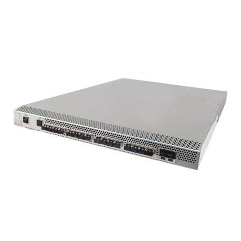
The DS-5000B switch is a 1U Fibre Channel switch with 32 fixed Fibre
Channel SFP ports that supports link speeds up to 1, 2, or 4 Gbit/sec.
It includes the Fabric Operating System and is compatible with the
entire EMC Connectrix B product family. The DS-5000B can operate
in a fabric containing multiple switches or independently.
The switch’s enclosure has forced-air cooling, with the fans pushing
the air from the rear part intake through the enclosure, and
exhausting across the SFP devices through venting holes in the front
panel (port side). The SFP media and integrated power supply/fan
assembly FRUs are hot-swappable so they can be removed and
replaced without interrupting the system power.
On the port side of the unit there are two port connections:
◆Ethernet Port: The DS-5000B provides a fully IEEE-compliant
10/100BaseT Ethernet port for switch management console
interface. When a device is connected to the port, both ends
negotiate to determine the optimal speed. The DS-5000B adopts a
1x2 RJ45 connector to provide Ethernet and serial ports to the
outside. The Ethernet connection uses one of two RJ-45 ports.
There are two integrated visible LEDs for Ethernet port (see
Figure 1 on page 13). One indicates transmit/receive activity and
one indicates speed (10 Mbps or 100 Mbps). The TCP/IP address
for the port can be configured from the serial port or directly from
the Ethernet port itself.
◆Serial Port: An RS-232 DTE terminal port is provided on the
DS-5000B switch. The serial console uses the other RJ45 port in
the 1x2 RJ45 connector. The serial port parameters are fixed at
9600 baud, 8 data bits, no parity and no hardware flow control
(except during boot up for the console port). This connector is for
initial IP address configuration and for recovery of the switch to
its factory default settings should Flash memory contents be lost.
The serial port connection is not intended for performance of
normal administration/maintenance functions.
The Fibre Optic cables, Ethernet cables and Serial port cables
connect in to the port side of the switch. AC power input cables
and the power supply/fan assembly FRUs are inserted and
removed from the port side of the switch.

Overview of the DS-5000B 13
Overview
The DS-5000B can be mounted in a 1U 19-inch Electronic Industries
Association (EIA) rack, with a height of 1U. Because of the shallow
depth, no rail kits are required for a rack mount, however the switch
can be installed using the optional rack mount kit. The DS-5000B can
also be used in a tabletop configuration.
Figure 1 shows the port side of the DS-5000B.
Figure 1 Port Side view of the DS-5000B
The Fibre Channel ports are numbered from left to right, in eight-port
groups, and are also numbered on the faceplate (see Figure 2).
Figure 2 Port numbering in the DS-5000B switch
1 System console port
2 System Ethernet port
3 Power supply/fan assembly Field Replaceable Unit (2x)
4 Power cord retainer (2x)
5 Switch ID pull out tab
4
5

14 EMC Connectrix B DS-5000B Hardware Reference Manual
Overview
Note: ISL Trunking is an optionally licensed software that allows you to
create trunking groups of ISLs between adjacent switches. For more
information about ISL Trunking, refer to the EMC Connectrix B Series
Fabric OS Administrator’s Guide.
The port side of the DS-5000B switch also displays the system status
LED, power status LED, and port status LEDs (see Figure 4 on
page 37).
Field Replaceable Units
Power supply/fan assembly units are the only Field Replaceable
Units (FRUs) in the DS-5000B. There are two power supply/fan
assembly units in the DS-5000B. They are hot-swappable and
redundant, and capable of functioning universally without voltage
jumpers or switches. The FRU units are identical and
interchangeable. The front panel of the FRUs has a status LED to
indicate status of the unit.

Managing the DS-5000B 15
Overview
Managing the DS-5000B
You can use the management functions built into the DS-5000B to
monitor the fabric topology, port status, physical status, and other
information to help you analyze switch performance and to
accelerate system debugging.
Note: The DS-5000B automatically performs power-on self-test (POST) each time it
is turned on. Any errors are recorded in the error log. For more information about
POST, see “POST and Boot specifications” on page 62.
You can manage the DS-5000B using any of the management options
listed in Table 1.
Note: To achieve in-band support for IP over Fibre Channel, the software
must be run on both the HBA and the switch, and it must be supported by
both the HBA and HBA driver.
Table 1 Management options for the DS-5000B
Management tool Out-of-band support In-band support
Command line interface (CLI)
Up to two admin sessions and four user sessions simultaneously. For more
information, refer to the EMC Connectrix B Series Fabric OS Administrator’s
Guide and the EMC Connectrix B Series Fabric OS Command Reference
Manual.
Ethernet or serial
connection
IP over Fibre Channel
Web Tools
For information, refer to the EMC Connectrix B Series Web Tools Administrator’s
Guide.
Ethernet or serial
connection
IP over Fibre Channel
Standard SNMP applications
For information, refer to the EMC Connectrix B Series MIIB Reference Manual.
Ethernet or serial
connection
IP over Fibre Channel
Fabric Manager (optional to purchase)
For information, refer to the Brocade Fabric Manager Administrator’s Guide.
Ethernet or serial
connection
IP over Fibre Channel
Management Server
For information, refer to the EMC Connectrix B Series Fabric OS Administrator’s
Guide and the EMC Connectrix B Series Fabric OS Command Reference
Manual.
Ethernet or serial
connection
Native in-band
interface
(over HBA only)

16 EMC Connectrix B DS-5000B Hardware Reference Manual
Overview
Supported features
The DS-5000B is shipped with the following features pre-installed:
◆Web Tools
◆Zoning
◆Full Fabric
The DS-5000B supports the following optional software, which you
can activate by purchasing a corresponding license key:
◆Performance Monitoring
◆Extended Fabrics
◆Fabric Watch
◆ISL Trunking
◆Ports on Demand (1 and 2)
For information on these features, refer to the EMC Connectrix B
Fabric OS Administrator’s Guide.
Ports On Demand
The DS-5000B has 32 ports. By default, ports 0-15 are enabled. To
enable additional ports, you must install Ports On Demand (POD)
licenses.
To enable ports 16 through 23, you must install the POD1 license. To
enable ports 24 through 31, you must install the POD2 license.
Although you can install the POD2 license without having the POD1
license installed, you cannot use ports 16 through 23 until the POD1
license is enabled.
For detailed information on enabling additional ports using the Ports
on Demand license, refer to the EMC Connectrix B Fabric OS
Administrator’s Guide.

Installation and Configuration 17
2
Invisible Body Tag
This chapter contains the following sections:
◆Items included with the DS-5000B .................................................. 18
◆Installation and safety considerations ............................................ 19
◆Attaching mounting ears to the DS-5000B switch......................... 21
◆Setting up the switch as a standalone unit..................................... 24
◆Configuring the DS-5000B ................................................................ 25
◆Recommendations for cable management ..................................... 34
Installation and
Configuration

18 EMC Connectrix B DS-5000B Hardware Reference Manual
Installation and Configuration
Items included with the DS-5000B
The following items are included with the standard shipment of the
DS-5000B:
◆The DS-5000B switch, containing two power supply/fan
assembly units
◆One accessory kit, containing the following items:
• 16 SFP (small-form-factor pluggable) transceivers (up to 32
optional)
•Mountingearsandscrews
• Rubber mounting feet (to be used when setting up the
DS-5000B as a standalone unit)
• Two grounded 6-ft. (approximately 1.83 meters)
country-specific power cords
• One serial cable, 10-ft. (approximately 3 meters) long

Installation and safety considerations 19
Installation and Configuration
Installation and safety considerations
You can install the DS-5000B in the following four ways:
◆In an EIA cabinet using the mounting ears provided with the
switch. This is the recommended installation method. For
instructions and more information, refer to “Installing the
DS-5000B switch (with mounting ears attached) in a standard
rack” on page 23.
◆As a standalone unit on a flat surface. For instructions and more
information, refer to “Setting up the switch as a standalone unit”
on page 24.
◆In an EIA cabinet using an optionally available rack mount kit.
Refer to the documentation that is shipped with the rack kit for
installation instructions.
To install and operate the switch successfully, ensure that the
following requirements are met:
◆The primary AC input is 90-264 VAC (switch autosenses input
voltage), 47-63 Hz.
◆The primary outlet is correctly wired, protected by a circuit
breaker, and grounded in accordance with local electrical codes.
◆The supply circuit, line fusing, and wire size are adequate, as
specified by the electrical rating on the switch nameplate.
For power supply information, refer to “Power supply specifications”
on page 55.
Verify that a minimum of 47 cubic feet/minute (79.8 cubic
meters/hour) of air flow is available to the air intake vents on the
nonport side of the switch.
Verify that the ambient air temperature does not exceed 40°Celsius
(104°Fahrenheit) and that the ambient humidity remains between 10
percent and 85 percent while the switch is operating.

20 EMC Connectrix B DS-5000B Hardware Reference Manual
Installation and Configuration
If installing the switch in a cabinet:
◆The cabinet must be a standard EIA cabinet.
◆Plan a cabinet space that is 1 rack unit high (1.75 inches; 4.44 cm),
19 inches (48.3 cm) wide, and at least 24 inches (61cm) deep.
◆Ground all equipment in the cabinet through a reliable branch
circuit connection and maintain ground at all times. Do not rely
on a secondary connection to a branch circuit, such as a power
strip.
◆Ensure that airflow and temperature requirements are met on an
ongoing basis, particularly if the switch is installed in a closed or
multirack assembly.
◆Verify that the additional weight of the switch does not exceed the
cabinet’s weight limits or unbalance the cabinet in any way.
◆Secure the cabinet to ensure stability in case of unexpected
movement.
Other manuals for Connectrix B Series
8
This manual suits for next models
1
Table of contents
Other EMC Switch manuals

EMC
EMC Connectrix B Series Quick user guide

EMC
EMC Connectrix B Series Quick user guide

EMC
EMC Connectrix DS-32M2 User manual

EMC
EMC Connectrix B Series Quick user guide

EMC
EMC DS-4900B Quick user guide

EMC
EMC Connectrix DS-32M2 User manual

EMC
EMC Connectrix B Series Quick user guide

EMC
EMC Connectrix ED-64M User manual

EMC
EMC Connectrix DS-24M2 User manual

EMC
EMC Connectrix B Series User manual