EMC Connectrix B Series Quick user guide

EMC Corporation
Corporate Headquarters:
Hopkinton, MA 01748-9103
1
-508-435-1000
www.EMC.com
EMC® Connectrix® B Series
MP-7500B
v5.2.1a
Hardware Reference Manual
P/N 300-004-888
REV A01
MP-7500BHW.book Page 1 Monday, June 11, 2007 3:39 PM

EMC Connectrix B Series MP-7500B Hardware Reference Manual
2
Copyright © 2007 EMC Corporation. All rights reserved.
Published June, 2007
EMC believes the information in this publication is accurate as of its publication date. The information is
subject to change without notice.
THE INFORMATION IN THIS PUBLICATION IS PROVIDED “AS IS.” EMC CORPORATION MAKES NO
REPRESENTATIONS OR WARRANTIES OF ANY KIND WITH RESPECT TO THE INFORMATION IN THIS
PUBLICATION, AND SPECIFICALLY DISCLAIMS IMPLIED WARRANTIES OF MERCHANTABILITY OR
FITNESS FOR A PARTICULAR PURPOSE.
Use, copying, and distribution of any EMC software described in this publication requires an applicable
software license.
For the most up-to-date listing of EMC product names, see EMC Corporation Trademarks on EMC.com.
All other trademarks used herein are the property of their respective owners.
MP-7500BHW.book Page 2 Monday, June 11, 2007 3:39 PM

EMC Connectrix B Series MP-7500B Hardware Reference Manual 3
Preface ............................................................................................................................. 7
Chapter 1 Introducing the MP-7500B switch
Overview of the MP-7500B.............................................................. 12
Port side of the MP-7500B switch................................................... 13
Nonport side of the MP-7500B........................................................ 15
Managing the MP-7500B.................................................................. 16
Supported features............................................................................ 17
Features not supported..............................................................17
Chapter 2 Installing and Configuring the MP-7500B Switch
Installation and safety considerations ........................................... 20
Items included with the MP-7500B................................................ 21
Setting up the MP-7500B as a standalone unit ............................. 22
Installing in an EIA cabinet ............................................................. 23
Initial setup of the MP-7500B.......................................................... 24
Provide power to the switch.....................................................25
Create a serial connection..........................................................25
Connect to the switch using the serial connection.................26
Set the switch IP address...........................................................26
Create an Ethernet connection..................................................27
Set the switch domain ID...........................................................27
Install SFPs and cable the switch..............................................28
Set the switch date and time .....................................................29
Synchronize local time with an external source.....................30
Correct the time zone of a switch.............................................30
Contents
MP-7500BHW.book Page 3 Monday, June 11, 2007 3:39 PM

EMC Connectrix B Series MP-7500B Hardware Reference Manual
4
Contents
FCIP and Fibre Channel Routing Services configuration.....32
Verify correct operation and back up with configuration....32
Recommendations for cable management.................................... 35
Chapter 3 Operating the MP-7500B
Interpreting LED activity................................................................. 38
LEDs on the port side of the switch.........................................38
LEDs on the nonport side of the switch..................................41
Interpreting POST results................................................................ 43
Maintaining the MP-7500B.............................................................. 44
Powering off the MP-7500B............................................................. 46
Chapter 4 Removing and Replacing System Components
Fan assembly replacement .............................................................. 48
Power supply replacement.............................................................. 52
Chapter 5 Product Specfications
Switch components........................................................................... 58
Weight and physical dimensions.................................................... 59
Facility requirements........................................................................ 60
Power supply specifications............................................................ 61
Environmental requirements .......................................................... 62
General specifications ...................................................................... 63
Data transmission ranges ................................................................ 65
Memory specifications..................................................................... 66
Fibre Channel port specifications................................................... 67
GbE port specifications.................................................................... 68
Serial port specifications.................................................................. 69
POST and Boot specifications......................................................... 70
POST.............................................................................................70
Boot...............................................................................................70
Regulatory compliance.................................................................... 71
FCC warning (US only) .............................................................71
MIC statement (Republic of Korea).........................................71
VCCI statement...........................................................................72
BSMI statement (Chinese).........................................................73
CE statement ...............................................................................74
MP-7500BHW.book Page 4 Monday, June 11, 2007 3:39 PM

5
EMC Connectrix B Series MP-7500B Hardware Reference Manual
Contents
Canadian requirements..............................................................74
Laser compliance.........................................................................74
RTC battery..................................................................................75
Electrical safety............................................................................75
Regulatory certifications............................................................76
Index................................................................................................................................ 77
MP-7500BHW.book Page 5 Monday, June 11, 2007 3:39 PM

EMC Connectrix B Series MP-7500B Hardware Reference Manual 7
Preface
As part of an effort to improve and enhance the performance and capabilities
of its product lines, EMC periodically releases revisions of its hardware and
software. Therefore, some functions described in this document may not be
supported by all versions of the software or hardware currently in use. For
the most up-to-date information on product features, refer to your product
release notes.
If a product does not function properly or does not function as described in
this document, please contact your EMC representative.
Audience This document is written for network administrators. It provides a
complete set of Connectrix B Series MP-7500B switch installation
procedures and an overview of the switch hardware. This document
is specific to the MP-7500B switch running Fabric OS v5.2.1a or
greater.
This document is organized to help you find the information that you
need as quickly and easily as possible. The document begins with an
introduction to the MP-7500B switch and proceeds through
installation and operation rocedures.
Supported hardware
and software Although many different software and hardware configurations are
tested and supported by EMC for this Fabric OS release,
documenting all possible configurations and scenarios is beyond the
scope of this document. This document is specific to Fabric OS
v5.2.1a. To obtain information about another Fabric OS version, see
the documentation specific to that version.
MP-7500BHW.book Page 7 Monday, June 11, 2007 3:39 PM

8EMC Connectrix B Series MP-7500B Hardware Reference Manual
Preface
Related
documentation Related documents include:
◆EMC Connectrix B Series Diagnostic and System Error Message
Reference Manual
◆EMC Connectrix B Series Fabric Watch Reference Manual
◆EMC Connectrix B Series Management Information Base (MIB)
Reference Manual
◆EMC Connectrix B Series Fabric OS Command Reference Manual
◆EMC Connectrix B Series Web Tools Administrator’s Guide
◆EMC Connectrix B Series ED-48000B Hardware Reference Manual
◆EMC Connectrix B Series PB-48K-16IP Hardware Reference Manual
Conventions used in
this document EMC uses the following conventions for special notices.
Note: A note presents information that is important, but not hazard-related.
CAUTION
!
A caution contains information essential to avoid data loss or
damage to the system or equipment. The caution may apply to
hardware or software.
IMPORTANT
!
An important notice contains information essential to operation of
the software. The important notice applies only to software.
MP-7500BHW.book Page 8 Monday, June 11, 2007 3:39 PM

EMC Connectrix B Series MP-7500B Hardware Reference Manual 9
Preface
Typographical conventions
EMC uses the following type style conventions in this document:
Where to get help EMC support, product, and licensing information can be obtained as
follows.
Normal Used in running (nonprocedural) text for:
• Names of interface elements (such as names of windows,
dialog boxes, buttons, fields, and menus)
• Names of resources, attributes, pools, Boolean expressions,
buttons, DQL statements, keywords, clauses, environment
variables, filenames, functions, utilities
• URLs, pathnames, filenames, directory names, computer
names, links, groups, service keys, file systems, notifications
Bold: Used in running (nonprocedural) text for:
• Names of commands, daemons, options, programs,
processes, services, applications, utilities, kernels,
notifications, system call, man pages
Used in procedures for:
• Names of interface elements (such as names of windows,
dialog boxes, buttons, fields, and menus)
• What user specifically selects, clicks, presses, or types
Italic: Used in all text (including procedures) for:
• Full titles of publications referenced in text
• Emphasis (for example a new term)
•Variables
Courier: Used for:
• System output, such as an error message or script
• URLs, complete paths, filenames, prompts, and syntax when
shown outside of running text.
Courier bold:Used for:
• Specific user input (such as commands)
Courier italic: Used in procedures for:
• Variables on command line
• User input variables
< > Angle brackets enclose parameter or variable values supplied by
the user
[ ] Square brackets enclose optional values
|Vertical bar indicates alternate selections - the bar means “or”
{ } Braces indicate content that you must specify (that is, x or y or z)
... Ellipses indicate nonessential information omitted from the
example
MP-7500BHW.book Page 9 Monday, June 11, 2007 3:39 PM
10 EMC Connectrix B Series MP-7500B Hardware Reference Manual
Preface
Product information — For documentation and release notes, or for
information about EMC products, licensing, and service, go to the
EMC Powerlink website (registration required) at:
http://Powerlink.EMC.com
Technical support — For technical support, go to EMC Customer
Service on Powerlink. To open a service request through Powerlink,
you must have a valid support agreement. Please contact your EMC
sales representative for details about obtaining a valid support
agreement or to answer any questions about your account.
Your comments Your suggestions will help us continue to improve the accuracy,
organization, and overall quality of the user publications. Please send
your opinion of this document to:
MP-7500BHW.book Page 10 Monday, June 11, 2007 3:39 PM

Introducing the MP-7500B switch 11
1
Invisible Body Tag
This chapter provides the following information about the MP-7500B
switch.
◆Overview of the MP-7500B............................................................... 12
◆Port side of the MP-7500B switch.................................................... 13
◆Nonport side of the MP-7500B......................................................... 15
◆Managing the MP-7500B................................................................... 16
◆Supported features............................................................................. 17
Introducing the
MP-7500B switch
MP-7500BHW.book Page 11 Monday, June 11, 2007 3:39 PM

12 EMC Connectrix B Series MP-7500B Hardware Reference Manual
Introducing the MP-7500B switch
Overview of the MP-7500B
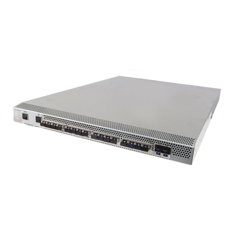
The MP-7500B is a 1U switch with 16 Fibre Channel SFP ports and 2
physical Gigabit Ethernet (GbE) ports. It includes the Fabric Operating
System and is compatible with the entire EMC Connectrix B product
family. It can operate independently or in a fabric containing multiple
switches.
This switch is intended as a platform for Fibre Channel Routing
Services and Fibre Channel over IP (FCIP). Refer to the Connectrix B
Series Fabric OS Administrator’s Guide for information on configuring
these features.
The MP-7500B provides the following features:
Rack mountable 1U chassis
◆2 redundant, hot-swappable power supplies
◆3 internal temperature sensors
◆3 redundant, hot-swappable fan FRUs. Each fan FRU has two fans
(for a total of 6 fans). Only one fan speed is displayed per FRU
using the fanShow command
◆16 Fibre Channel SFP ports supporting Fibre Channel Routing
Services with link speeds up to 1-, 2-, or 4-Gbit/sec
◆2 GbE ports supporting the FCIP and Fibre Channel Routing
Services features with link speeds up to 1-Gbit/sec:
• Each GbE port can support up to 8 FCIP tunnels
• Each FCIP tunnel is represented and managed as an Fibre
Channel E_Port
• Fibre Channel Routing Services functionality can be used over
the FCIP link
• Fabrics connected through FCIP merge if the ports are
configured as VE_Ports, and do not merge if they are
configured as VEX_Ports. If VE_Ports are used in an Fibre
Channel Routing Services backbone fabric configuration, then
the backbone fabric merges but the EX_Port attached to edge
fabrics do not merge. For more information see the Connectrix
B Series Fabric OS Administrator’s Guide.
Once the switch is configured, the switchShow command displays 32
Fibre Channel ports (port numbers 0 through 31) and 2 GbE ports. The
first 16 Fibre Channel ports are physical ports on the MP-7500B, Ports
16-23 are virtual ports associated with the GE0 physical GbE link and
ports 24-31 are virtual ports associated with GE1 physical GbE link. The
GbE ports are displayed as ge0 and ge1 and are not assigned port
numbers or area numbers.
MP-7500BHW.book Page 12 Monday, June 11, 2007 3:39 PM

Port side of the MP-7500B switch 13
Introducing the MP-7500B switch
Port side of the MP-7500B switch
Figure 1 shows the port side of the MP-7500B.
Figure 1 Port side view of the MP-7500B
IOIOI
!
GE1GE01514131211109876543210
scale: 1/8" = 1"
ATTENTION:
Maximum screwlengthfor rack
mounting tobe 5mm or13/64 in.
IOIOI
!
GE1
GE0
15
14
13
12
11
10
9
8
7
6
5
4
3
2
1
0
!
1
7
2 3 4 5
7
6
1 MP-7500B 5 GbE ports (2)
2 Console Managment Port 6 System Status LED (top)
3 Ethernet Management Port System Power LED (bottom)
4 Fibre Channel Ports (16) 7 IP Address pull out tab
MP-7500BHW.book Page 13 Monday, June 11, 2007 3:39 PM

14 EMC Connectrix B Series MP-7500B Hardware Reference Manual
Introducing the MP-7500B switch
The Fibre Channel ports are numbered from left to right, in eight-port
groups, and are also numbered on the faceplate (see Figure 2).
Figure 2 Port numbering in the MP-7500B
The port side of the MP-7500B also displays the system status LED,
power status LED, and port status LEDs (Figure 4 on page 39).
IOIOI
!
GE1GE015141312111098
15141312111098
76543210
76543210
scale: 5/16" = 1"
GE1GE0
6
1
5432
1 MP-7500B 4 Fibre Channel Ports 8 through 11
2 Fibre Channel Ports 0 through 3 5 Fibre Channel Ports 12 through 15
3 Fibre Channel Ports 4 through 7 6 GbE ports (2)
MP-7500BHW.book Page 14 Monday, June 11, 2007 3:39 PM

Nonport side of the MP-7500B 15
Introducing the MP-7500B switch
Nonport side of the MP-7500B
Figure 3 shows the nonport side of the MP-7500B, which contains the
power supplies (including the AC power receptacle and AC power
switch) and fans.
Figure 3 Nonport side of a MP-7500B
scale: 5/16" = 1"
scale: 1/8" = 1"
ATTENTION:
Maximum screwlength forra
ck
mountingtobe5
mm or13/64in.
1
76
2
43 5
1 MP-7500B 5 Fan Assembly #2
2 Nonport Side of Switch 6 Fan Assembly #1
3 Power Supply #2 7 Power Supply #1
4FanAssembly#3
MP-7500BHW.book Page 15 Monday, June 11, 2007 3:39 PM

16 EMC Connectrix B Series MP-7500B Hardware Reference Manual
Introducing the MP-7500B switch
Managing the MP-7500B
You can use the management functions built into the MP-7500B to
monitor the fabric topology, port status, physical status, and other
information to help you analyze switch performance and to
accelerate system debugging.
Note: The MP-7500B automatically performs power-on self-test (POST) each
time it is turned on. Any errors are recorded in the error log. For more
information about POST, see “POST and Boot specifications” on page 70.
You can manage the MP-7500B using any of the management options
listed in Table 1.
Table 1 Management options for the MP-7500B
Management tool Out-of-band
support In-band support
Command line interface (CLI)
Up to two admin sessions and four user sessions simultaneously. For
more information, see the Connectrix B Series Fabric OS Administrator’s
Guide and the Fabric OS Command Reference Manual.
Ethernet or serial
managment port
connection
IP over Fibre Channel
Fabric Manager
For information, see the Fabric Manager Administrator’s Guide.Ethernet or serial
managment port
connection
IP over Fibre Channel
Web Tools
For information, see the Connectrix B Series Web Tools Administrator’s
Guide.
Ethernet or serial
managment port
connection
IP over Fibre Channel
Standard SNMP applications
For information, see the Connectrix B Series Fabric OS Management
Information Base (MIB) Reference Manual..
Ethernet or serial
managment port
connection
IP over Fibre Channel
Management Server
For information, see the Connectrix B Series Fabric OS Administrator’s
Guide and the Connectrix B Series Fabric OS Command Reference
Manual.
Ethernet or serial
managment port
connection
Native in-band interface
(over HBA only)
MP-7500BHW.book Page 16 Monday, June 11, 2007 3:39 PM

Supported features 17
Introducing the MP-7500B switch
Supported features
IMPORTANT
!
References in the Fabric OS 5.2.1 documentation set specific to
features/functionality available on the PB-48K-18i blade, such as
FCR/FCIP functionality and port configurations, also apply to the
MP-7500B.
The MP-7500B supports the following features that are included with
the firmware:
◆Web Tools
◆Fibre Channel Routing Services
◆Zoning
◆Full Fabric
The following optional software is available with the purchase of a
specific license key:
◆FC over IP SAN Extension (FCIP)
◆Performance Monitoring
◆Fabric Watch
◆Extended Fabric
◆Trunking
For information on these features, see the Connectrix B Series Fabric OS
Administrator’s Guide.
Features not supported
The following feature is not supported:
◆ISL Trunking is not supported on EX_Ports on the MP-7500B.
MP-7500BHW.book Page 17 Monday, June 11, 2007 3:39 PM

Installing and Configuring the MP-7500B Switch 19
2
Invisible Body Tag
This chapter provides the following information on installing the
MP-7500B.
◆Installation and safety considerations ............................................ 20
◆Items included with the MP-7500B ................................................. 21
◆Setting up the MP-7500B as a standalone unit............................... 22
◆Installing in an EIA cabinet .............................................................. 23
◆Initial setup of the MP-7500B........................................................... 24
◆Recommendations for cable management ..................................... 35
Installing and
Configuring the
MP-7500B Switch
MP-7500BHW.book Page 19 Monday, June 11, 2007 3:39 PM
20 EMC Connectrix B Series MP-7500B Hardware Reference Manual
Installing and Configuring the MP-7500B Switch
Installation and safety considerations
You can install the MP-7500B in the following ways:
◆As a standalone unit on a flat surface. For instructions and more
information, see “Setting up the MP-7500B as a standalone unit”
on page 22.
◆In an EIA cabinet using the optional rack mount kit. For more
information, see “Installing in an EIA cabinet” on page 23.
To install and operate the switch successfully, ensure that the
following requirements are met:
◆The primary AC input is 100-240 VAC (switch autosenses input
voltage), 47-63 Hz.
◆The primary outlet is correctly wired, protected by a circuit
breaker, and grounded in accordance with local electrical codes.
◆The supply circuit, line fusing, and wire size are adequate, as
specified by the electrical rating on the switch nameplate.
For power supply information, see “Power supply specifications” on
page 61.
To ensure adequate cooling, install the switch with the nonport side,
which contains the air intake vents, facing a cool-air aisle.
Verify that the ambient air temperature does not exceed 40°C (104°F)
and that the ambient humidity remains between 20% and 85% while
the switch is operating.
If installing the switch in a cabinet:
◆The cabinet must be a standard EIA cabinet.
◆Plan a cabinet space that is 1U (1.75 in.; 4.44 cm), 19 in. (48.3 cm)
wide, and at least 24 in. (61cm) deep.
◆Ground all equipment in the cabinet through a reliable branch
circuit connection and maintain ground at all times. Do not rely
on a secondary connection to a branch circuit, such as a power
strip.
◆Ensure that airflow and temperature requirements are met on an
ongoing basis, particularly if the switch is installed in a closed or
multirack assembly.
◆Verify that the additional weight of the switch does not exceed the
cabinet’s weight limits or unbalance the cabinet in any way.
•Secure the cabinet to ensure stability in case of unexpected movement
MP-7500BHW.book Page 20 Monday, June 11, 2007 3:39 PM
Other manuals for Connectrix B Series
8
This manual suits for next models
1
Table of contents
Other EMC Switch manuals

EMC
EMC Connectrix DS-24M2 User manual

EMC
EMC DS-4900B Quick user guide

EMC
EMC Connectrix B Series Quick user guide

EMC
EMC DS-16B User manual

EMC
EMC Connectrix DS-24M2 User manual

EMC
EMC Connectrix DS-32M2 User manual

EMC
EMC Connectrix B Series Quick user guide

EMC
EMC Connectrix B Series User manual

EMC
EMC Connectrix B Series Quick user guide

EMC
EMC Connectrix B Series Quick user guide