Emerson Power Transmission Kop-Flex KOP-GRID H Series User manual

1
©EmersonPowerTransmissionManufacturing,L.P.1998.AllRightsReserved.
Installation and Alignment
Instructions
FORM 17200
DECEMBER, 1996
The trademarks KOP-FLEX,KOP-GRID and are registered trademarks of
Emerson Power Transmission Manufacturing. L. P. and/or Kop-Flex, Inc.
KOP-GRID®
Tapered Grid
Coupling -Type H
Horizontal Split Cover
INSTALLATION and ALIGNMENT
INSTRUCTIONS
Theseinstructions apply to KOP-GRID®type Htapered grid
couplings.
This sheet may be supplemented by Special Instructions
suppliedwith thecoupling formodifications andvariations of
these couplings. For dimensions, ratings, maximum bores,
interferencefits, and othertechnical information,pleaserefer
toBulletin 1700.
When working on rotating equipment be sure to lock out the
starting switch of prime mover so the equipment cannot be
started until work is complete, checked, and personnel are
safely away. Proper installation per this product instruction
sheet must be observed.Failure to do so may void warranty
and could result in injury to person or property.
MAINTENANCE and LUBRICATION
Lubricate the KOP-GRID®coupling with grease only. Use
KOP-FLEX®
KSG coupling grease or other grease meeting
theminimum specificationsshown.
Do not use oil in KOP-GRID®couplings.
Coupling lubrication is critical.The use of proper and suffi-
cientlubrication is partof a successfulinstallation.
Lubricants should be checked to ensure the proper level is
maintained and that the lubricant is free of contaminates. In
an average industrial application, the coupling should be
checkedfor lubricantcontaminationand replenishedwiththe
propervolumeevery twelvemonths. Conditions suchas very
slowspeed, reversing drives,high heatand severe environ-
mentsmay requiremore frequentlubrication.
RECOMMENDED LUBRICANT
KOP-FLEX®KSG Coupling Grease
Thisgreaseisspecificallycompoundedforstandardcouplings
toprovide improved lubricationand resistanceto centrifugal
separation.When KSG grease is used, lubrication intervals
may be extended, based upon operating experience. KSG
couplinggreaseis availablefrom Kop-Flex orauthorizeddis-
tributorsof Kop-Flex power transmission products.
OTHER GREASES
Alternate lubricating greases should equal or exceed the
specifications for KOP-FLEX®KSG coupling grease (speci-
ficationsheet3532 isavailable uponrequest).Greases other
thanKSG shouldmeet theseminimum specifications:
Grade:NLGI #1
Base oilViscosity:Min:
3000SSU at 100°F
160 SSU at 210°F
DroppingPoint,Min.:190°F
FourBallWear, ASTM D-2266:
.500mm Maximum
BaseOil Content:87%Minimum
K36 Factor, ASTM D-4425:
KSG: K36 = 8/25 =.33
Required:Rustand Oxidation Inhibitors
E.P.Additives
KOP-FLEX, INC., P.O. BOX 1696, BALTIMORE MARYLAND 21203, 410-768-2000
KOP-FLEX CANADA, LTD., 19 METEOR DRIVE, REXDALE, ONTARIO, CANADA M9W-1A3, 416-675-7144
Emerson Power Transmission
Emerson Power Transmission
GRIDHUB
TYPE H COVER
TAPERED GRID
SEAL
COVER
FASTENERS
GASKET
SURFACE
↓
↓
CAUTION
If assembled
incorrectly,
equipment failure
and personal
injury may result.
Disconnect all power while adjusting units
2©EmersonPowerTransmissionManufacturing,L.P.1998.AllRightsReserved.
Themost reliabletestof asuitablelubricant isoften theresult
of user experience and satisfaction. If a lubricant has been
knowntosludge, separateinto heavycomponentsor dryout,
consider the use of KOP-FLEX®KSG grease.
1. HUB INSTALLATION
Verify all parts are on hand and are as ordered, check that
the hub bores are correct.Prepare shafts by removing dirt
and burrs. Lightly apply grease on seals and place them on
shafts, before installing the hubs. Mount the hubs on their
shafts,withhub faceflushwiththe shaftend.Properlytighten
setscrews when furnished.For vertical shafts, seal the key-
Figure 2
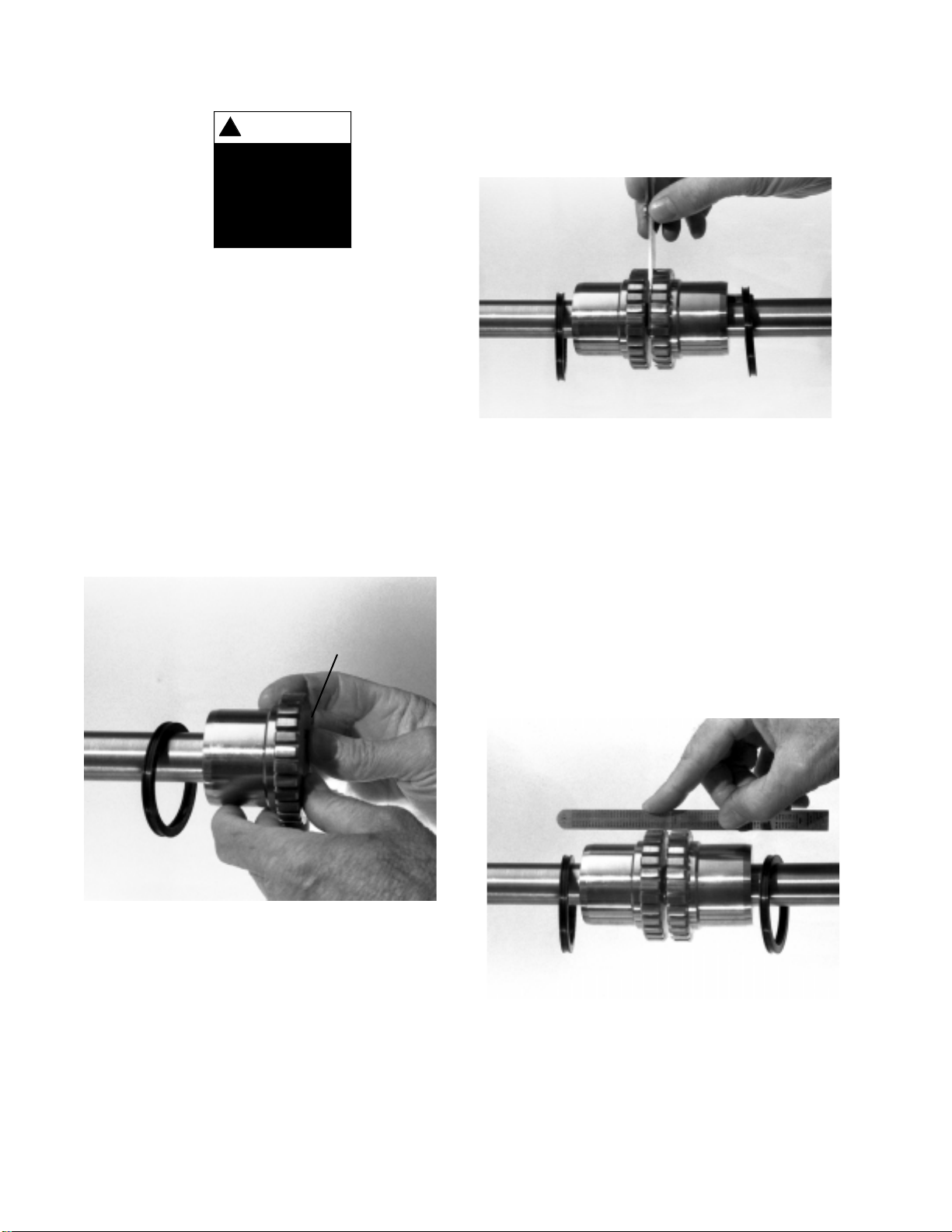
2. SHAFT SEPARATION & ANGULAR ALIGNMENT
Usea feeler gaugeto measurethegap betweenhubfaces at
4points90°apart.Thegapshouldnotexceedthe valuespeci-
fied in Table 1.Position equipment to obtain best alignment.
The measured difference between minimum and maximum
valueshould notexceedthe angularlimit specifiedinTable1.
Important Safety Instructions
Before start-up . . . forreasons ofsafety andto extendshaft
couplinglife, followthese requirements.
1. Coupling guards protect personnel. ALL COUPLINGS
MUST BE COVEREDWITH A GUARD AS PER OSHA
REQUIREMENTS.
2. Recheck alignmentafterall foundationboltsandmechani-
calconnections aretightened.
3. Make sure all fasteners are properly installed and tight-
ened.
4. Take the time to double check your work.
5. Only authorized Kop-Flex replacement parts are to be
used.
6. Call Kop-Flex for any clarification or questions.
WARNING
!
Failure to observe
safety precautions
could cause
personal injury
or equipment
damage.
INSTALL
SEAL
FIRST
HUB
FACE
Figure 1
↓
wayto prevent greaseleakage. For interferencefit, heatthe
hub in an oven to 300°F (150°C) before mounting the hub.
NEVER exceed 600°F (300°C).
Note: Allow heated hubs to cool to room temperature
before coupling alignment and assembly.
Figure 3
3. OFFSET ALIGNMENT
Useastraightedgeandfeeler gaugeto alignshaftsat4points
90° apart.The offset (parallel misalignment) should not ex-
ceed the offsetlimit specified inTable 1.
3
©EmersonPowerTransmissionManufacturing,L.P.1998.AllRightsReserved.
Adjust equipment as required. Recheck steps 2 and 3 after
tighteningthe foundationboltsand realignthe coupling,ifthe
offsetand angularmeasurementsexceedthe valuesinTable
1.Note: Bestcoupling alignmentis obtainedby using dial in-
dicators.If dial indicators are used,always rotatethe hub on
whichthe indicatoris mounted to obtain readings.
Figure 4
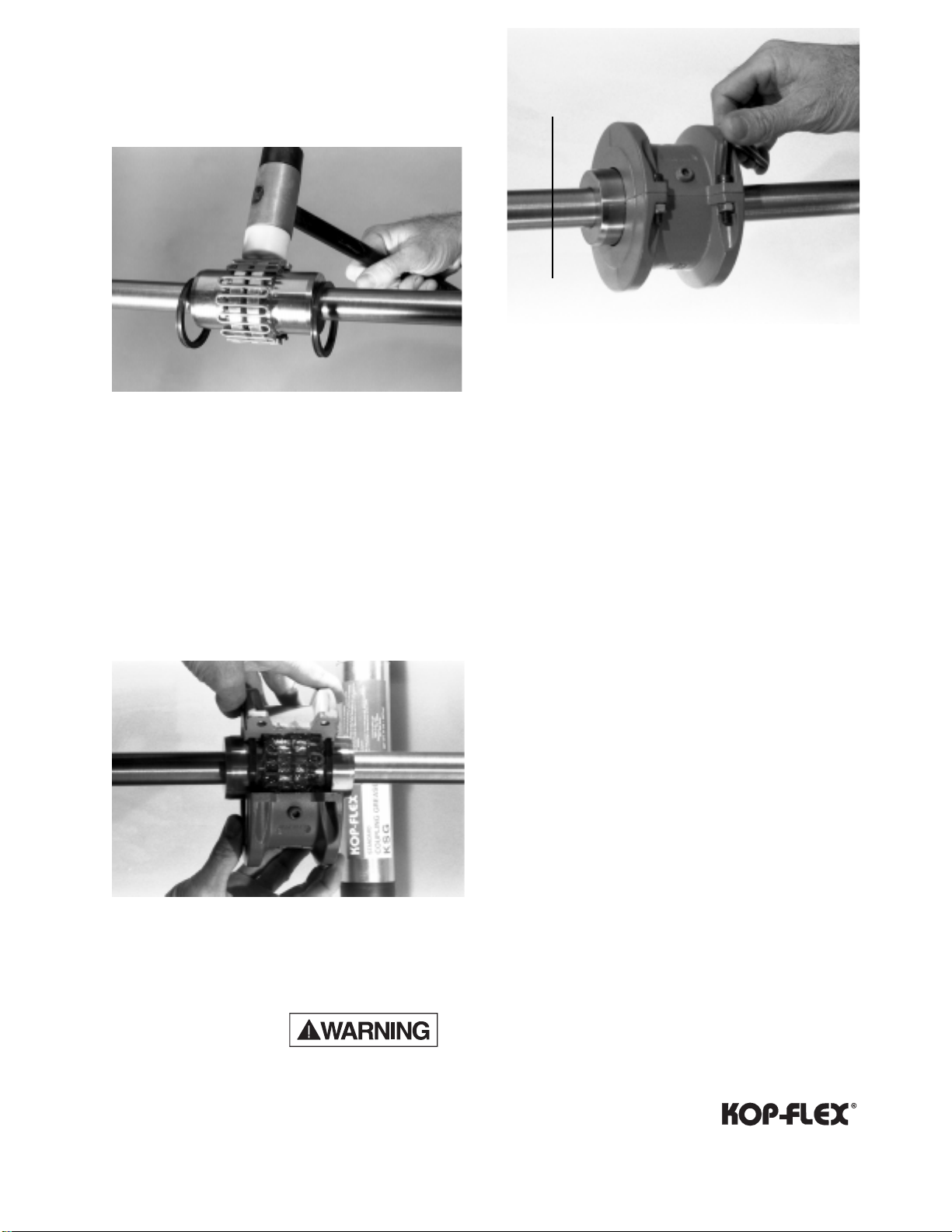
4. TAPERED GRID INSTALLATION
Fillthe hubgapand gridteeth grooves withKOP-FLEX®KSG
grease or a comparable alternate. Lightly open the grid to
engagewith thegrooveson thehub.Use asoft mallettoseat
thegrids inthe tapered teethgrooves. Fortapered gridsthat
aresupplied with morethan one segment,make sureall the
segment’s openends are onthe same side.
Figure 5
Figure 6
5.COVER INSTALLATION & LUBRICATION
Pack the grid with additional KSG grease or the equivalent
and wipe off the excess flush with the top of the grid. Slide
seals over the hub and adjust to line up with the cover seal
grooves. Place gaskets on both flanges of the lower cover
and install top cover. Align cover match marks on the same
side. For vertical applications or inclined shafts, make sure
the match marks are UP, or on the higher side.Tighten the
cover fasteners to the cover bolt torque value specified in
Table 1.For lubrication, remove the two lube plugs from the
covers and fill with KOP-FLEX®KSG grease or specified al-
ternate, until thegreasestartsseepingoutfrom theotherlube
hole. Re-install the two lube plugs in the covers and tighten
securely.
Note: Do not operate coupling without the lube plugs.
GASKET
COVER MATCH
MARKS
→
↓
→
Emerson Power Transmission
Disconnect all power while adjusting units
4©EmersonPowerTransmissionManufacturing,L.P.1998.AllRightsReserved.
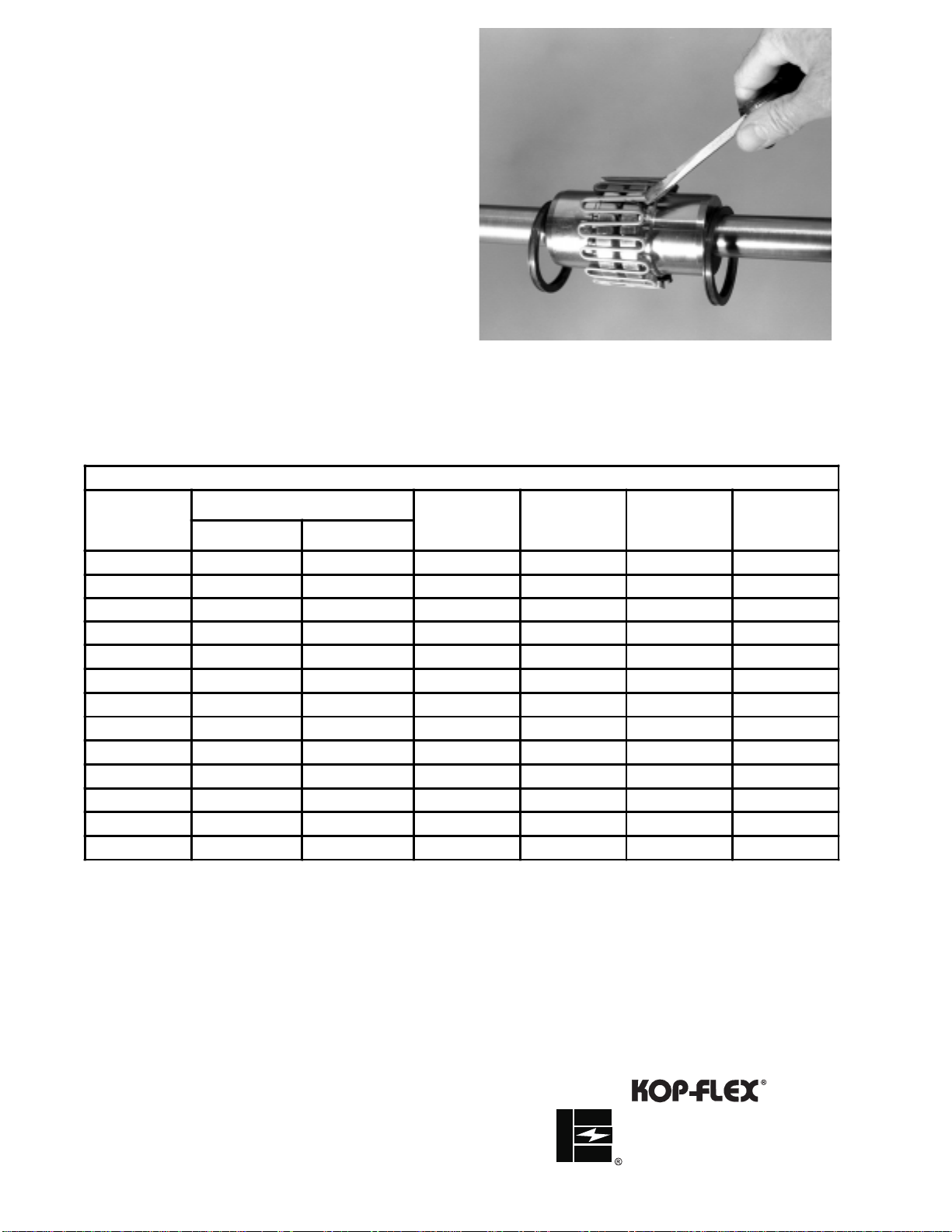
GRID REMOVAL:
Remove the coupling cover assembly.Insert a rod or screw
driverintotheopen endloopofthe taperedgrid.Usethe teeth
onthe coupling hubas asupport to graduallyand gentlypry
offthe grid,proceeding alternately fromside toside.
Figure 7
Table 1
Form17200 12/4/96
Printed in U.S.A.
INSTALLATION AND ALIGNMENT VALUES
SIZE
MAXIMUM RECOMMENDED
MISALIGNMENT LIMITS GAP
(IN.)
COVER
BOLT
TORQUE
(LB-IN.)
ALLOWABLE
MAXIMUM
SPEED
(RPM)
LUBE/
GREASE
WEIGHT
(LB.)
OFFSET
(IN.) ANGULAR
(IN.)
1020 0.006 0.003 0.125 100 4,500 0.07
1030 0.006 0.003 0.125 100 4,500 0.07
1040 0.006 0.003 0.125 100 4,500 0.11
1050 0.008 0.004 0.125 200 4,500 0.11
1060 0.008 0.005 0.125 200 4,350 0.20
1070 0.008 0.005 0.125 200 4,125 0.24
1080 0.008 0.006 0.125 200 3,600 0.37
1090 0.008 0.007 0.125 200 3,600 0.55
1100 0.010 0.008 0.188 260 2,440 0.95
1110 0.010 0.009 0.188 260 2,250 1.12
1120 0.011 0.010 0.250 650 2,025 1.61
1130 0.011 0.012 0.250 650 1,800 2.00
1140 0.011 0.013 0.250 650 1,650 2.50
KOP-FLEX, INC.
EMERSON POWER TRANSMISSION
P. O.Box 1696
Baltimore,MD 21203-1696


