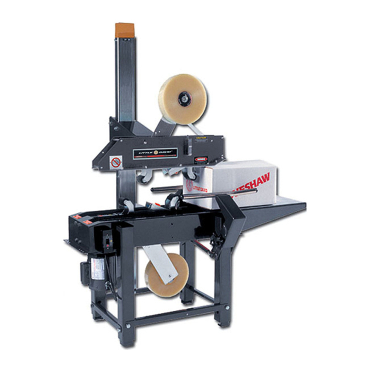
Loveshaw Little David LD16AR User manual

Little David™ Case Sealer
LD16AR FullyAutomatic Random Top and
Bottom Case Sealer
Version: 01
Operator’s Manual

L I T T L E D A V I D ™ C A S E S E A L E R
LD16AR Operation
Copyright Loveshaw
Loveshaw, Inc.
2206 Easton Turnpike, PO. Box 83
South Canaan, PA 18459
Tel: 1-800-962-2633 • 570-937-4921
Fax: 570-937-4016
www.loveshaw.com
PADLOCKER, LTD.
Unit 9 Brunel Gate
West Portway Industrial Estate
Andover, Hampshire SP10 3SL
ENGLAND
Tel: 264-357511
Fax: 264-355964
Wednesday, June 07, 2017


Table of Contents
Chapter 1: Introduction
Chapter 2: Operating Safety
Chapter 3: Overview
Chapter 4: Installation
Chapter 5: Theory of Operation
Chapter 6: Machine Components
Chapter 7: Maintenance

Chapter 8: Troubleshooting
Chapter 9: Warranty
Chapter 10: Assembly Drawings and Schematic

Introduction
hank you for purchasing the Little David™ case sealer, the
LD16AR. The LD16AR is a fully-automatic top and bottom case
sealer. The LD16AR is a robust built 24/7 case sealer constructed
of quality materials, linear bearings, pneumatic and electrical
components.. All employees who will be required to operate and maintain the
case sealer must read this manual to ensure safe operation as well as proper
set-up and maintenance throughout the life of the machine. After reading
this manual, you will know how to perform the following functions,
How to operate the machine safely.
How to set the conveyor height of the machine.
Troubleshooting and replacement of worn or defective parts.
Throughout this manual there are several illustrations designed to help
you perform the variety of tasks described.
Chapter
1
T

Operating Safety
Observe the warnings and cautions below when using the Little David LD16AR case sealer.
Within this manual all safety labels are depicted with location and part number. If a safety,
label is missing or not legible it must be replaced immediately. Failure to follow safety
labels can lead to injury or damage to the machine.
Instruction:RequirementtoSystemOperation
An electrical service must be hard wired to the main control panel. The main
enclosure has a door power disconnect.
Warning: Potential Bodily Injury
Always disconnect all sources of energy to the machine before performing maintenance.
Sources of energy include electrical and pneumatic. Refer to your company’s lock out
tag out procedures.
Never bypass or remove safety guards from the machine or tape cartridge.
Never override safety devices such as Emergency Stop switches.
Never adjust the machine or tape cartridges when the machine is operating.
Never place hands or body inside confines of the machine unless the machine has been
placed in an E-Stop condition.
Never wear jewelry, loose clothing, such as ties, scarves etc and long hair must be pulled
back when operating this machine.
Never pull a jammed box out of the machine while it is in operation. Stop machine and
raise head with the head raise button.

Chapter
2
Instruction:
Warning:
Warning:
Warning:
Warning:
Warning:
Warning:
Warning:

This manual contains operator information for Little David Application Equipment. It is directed toward the person who
operates and maintains the machine. Read through the manual completely before operating the machine. Thereafter,
refer to it as necessary.
Take special note of all warnings, cautions, and maintenance instructions. Like any other piece of equipment, the Little
David Case Sealer functions best when maintained and used correctly.
Caution: Potential Machine Damage:
Provide and use proper electrical power.
Do not operate, maintain, or otherwise use this machine, except as described in this
manual.
Special instruction:
The bottom belt assembly incorporates adjustable belt guards. The guards are made adjustable to maintain 1/32” gap
between the belt and the guard itself. This eliminates a pinch point between the guard and the belt. The guards are
located at the rear of the machine where the belt wraps around the drive pulleys. The guards must be adjusted inward as
the belts wear. It is mandatory the gap be adjusted to no more than 1/32” clearance between the top of the belt and the
guard itself. The guard is simply adjusted by loosening two panel head machine screws and sliding the guard inward to
maintain the 1/32” gap. Failure to adjust the guards may cause injury.
Caution:
Caution:
Mounting screws
Drive belt
Belt guard
Gap not to exceed
1/32”

Case Sealer Sections
Overview
This manual covers several parts of the machine. The following
diagram identifies the key sections of the machine.
Chapter
3
Linear Actuator
Head Assy.
Height Sensing
Carriage
Side Rails
Side Rails
Squeezer Assy.
Control Station
Air Regulators
Air Regulators
Balance Air
Tank
Kicker
Roller Drive

Machine Specifications
Machine dimensions:
Height: 87.375” @ 22 1/4” conveyor height
Length: 110”
Width: 48”
Conveyor height: 22 1/4” to 28.25” –Standard
Electrical Requirements:
Standard Voltage: 120/1/60 with 20 amp dedicated
service.
Optional voltages are available consult factory.
Operating speed:
Standard belt speed: 150 ft/min

Air Requirement:
6 scfm @ 85 psi –maximum throughput based on
maximum box range.
Machine box capacity:
Length: - 8” to 24”
Width: - 5 ½” to 20”
Height: 5 ½” to 20”

Installation
lways check for any signs that the machine may have been damaged
before fully removing it from the shipping skid. If machine arrives
damaged contact Loveshaw immediately to help in filing a claim
with shipping company.
Section 1: Placing the Machine
Step One: Carefully remove the machine from the shipping skid.
Remove all fasteners and brackets holding the machine to the skid.
Step Two: Take care removing the machine from the skid as it is
very heavy. Use a forklift or similar device to complete this task
Step Three: Move machine to designated location. It will be
necessary to bolt the two sections of the machine together and reconnect
all of the pneumatic and electrical connections.
Step Four: It may be necessary to adjust the conveyor height
of the machine. The legs on the machine are adjustable by removing the
hardware and lowering the leg to its proper position. Make sure you
reuse all of the hardware that you removed. Do not over extend the leg
extensions. The use of a jack or forklift is required.
Step Five: Connect compressed air and electricity to the
machine.
Chapter
4
A

Attach The Machines:
Place the machine segments and attach them together using
the spacers and hardware provided.
ATTACHMENT HARDWARE
(13mm wrenches)

Leg Extension Taper
Leg Extension Box Sizer
Inner leg
Outer leg
Leg Ext. Hardware
(13mm wrench)
Inner leg
Outer leg
Leg Ext. Hardware
(13mm wrench)

Theory of Operation
LD16AR
The LD16AR will automatically adjust to the width and height of
the box to be sealed, while folding all of the top flaps.
With the machine started, a box will approach the entrance of the
machine from the infeed conveyor. If the machine is ready to
accept a box the indexing gate will be in the lowered position and
the box will be allowed to enter the machine. As the box enters
the machine the bottom power rollers will begin to aid in moving
the box further into the machine. When the box triggers “PE1” a
signal is sent to the programmable logic controller, (PLC) to
energize solenoid valve “SV2” and raise the indexing gate. The
indexing gate will raise up underneath the back of the box so that
the next box in line doesn’t follow the box being processed into
the machine. The box will continue to move forward until
“PE3” is triggered. When “PE3” is triggered the PLC tells the
variable frequency drive, (VFD), controlling the bottom power
rollers to stop. This stops the progress of the box thru the
machine. The PLC then simultaneously energizes “SV3” and
“SV4B”. “SV3” moves the centering arms inward to center the
box. “SV4B” lowers the height sensing carriage down to the top
of the vertical box flaps. When the height sensing carriage
reaches the top of the flaps “PE2” is triggered. When “PE2” is
triggered the PLC reads the distance or positional information
from the linear transducer “LT1” and the ultrasonic sensor “U1”.
Once the positional information is collected “SV3” and “SV4B”
are de-energized and “SV4A” is energized. This causes the
centering arms and height sensing carriage to return to their home
Chapter
5

position. The PLC uses the positional information to calculate
the proper linear actuator position for the box measured. Once
the height has been determined the information is sent from the
PLC to the linear actuator. The linear actuator then moves to the
proper position for the box measured. Once in position the PLC
signals the VFD to restart the bottom power rollers and move the
box into the taping section of the machine.
At this time the
PLC also energizes “SV2” which lowers the indexing gate
and allows the next box into the box sizing portion of the
machine.
The box now is transitioned from the bottom power
rollers to the rough top belt drive of the taping section of the
machine. “PE4” is the next sensor to be triggered by the box.
When “PE4” is triggered the PLC energizes “SV5” which closes
the side rails on the sides of the box to keep it centered through
the rest of the machine. Next the front minor folder collides with
the suppressor and folds the flap down to the horizontal position.
The box triggers “PE4” and has no effect until the eye becomes
unblocked again, (trailing edge of the box). Once the box clears
“PE4” the PLC energizes “SV6”. This causes the rear flap kicker
pivot downward, (kick), and fold the rear minor flap of the box to
a horizontal position. After a predetermined amount of time
“SV6” is de-energized and the flap kicker returns to its home
position. The rough top belts continue to move the box through
the stationary major flap folding bars. The bars fold the vertical
major flaps to horizontal position. The box continues to move
toward the discharge of the machine triggering “PE8” next.
When “PE8” is triggered the PLC energizes “SV7” this pivots the
top flap squeezing arms in toward the box just prior to sealing the
top of the box with tape. The box next encounters the bottom
tape cartridge and shortly after the top tape cartridge. Both
cartridges perform in the same fashion, mechanically applying
either 2” or 3” pressure sensitive tape to the top and both leading
and trailing panels of the box. After a predetermined amount of
time ”SV7” de-energizes and the top flap squeezing arms return
to their home position. The box next triggers “PE6” and has no
effect until the eye becomes unblocked again, (trailing edge of the
box). Once the box clears “PE6” the PLC allows the head of the
taper to move into position to process the next box. The PLC
also de-energizes “SV5” which opens the side rails back to their

home position. The box now completely exits the machine and
continues on.
Key design features:
The LD16AR incorporates an indexing gate. The indexing gate
allows one box to enter the machine at a time while holding back
the next box to be processed. The indexing gate is pneumatically
actuated and controlled by the PLC. The indexing gate must lift
up the trailing end of the box to properly index. In some
situations it may be necessary to adjust the air pressure to
accomplish proper indexing.
The LD16AR incorporates a box sizing segment of the machine.
The sole purpose of this segment is to accurately determine the
size of a closed box. To do this the machine moves the box into
position, centers the box and moves the box height sensing platen
down to the top of the open, vertical major and minor box flaps.
At this point the PLC collects measurement from the height and
with sensors. The PLC converts these measurements into a
physical position for the taper head.
The LD16AR incorporates a servo driven linear actuator to
accurately position the taping head. When the box sizing segment
determines the box size the PLC sends the linear actuator a
command to move into position to process the box measured.
The LD16AR incorporates power top squeezers. The squeezers
help minimize the gap between the top major flaps just prior to
sealing the box. The squeezers are pneumatically actuated and
self-centering.
The LD16AR incorporates a pneumatic pressure switch. This
ensures that the machine has the proper pressure before allowing
it to start and run. The pneumatic switch only sends a signal to
the PLC if the proper amount of air pressure is present. Proper
pressure is imperative for the linear actuator balance system.
Without proper pressure the linear actuator will fault.

Machine Components
Control Station
The control station consists of an electrical enclosure, push pull
mushroom head emergency stop switch, main electrical
disconnect and control buttons and switches.
Chapter
6
E-STOP
START
HEAD
RAISE
CONTROL
STOP
E-STOP
RESET
MAIN / DOOR
DISCONECT
TEST / RUN
SWITCH
HEAD
LOWER
HOME

Pneumatic regulators
The regulators optimize the machine for the customers’ specific
needs. For a full list of regulators refer to the pneumatic
schematics at the end of this manual. Regulators “R1” is the
main air pressure and is set to 80 psi from the factory.
Regulator “R2” controls the indexing gate. Depending on the
weight of the boxes this regulator may need to be adjusted. For
the indexing gate to work properly the gate must lift up the back
of the box. If the box your trying to process is not being lifted up
by the gate you will have to increase the pressure on regulator
“R2”.
Regulator “R3” controls the centering arms on the box sizer. The
centering arms job is to center the incoming box in the machine.
Depending on the weight and strength of the boxes being
processed it may be necessary to adjust regulator “R3”. You need
enough pressure to center the boxes but too much pressure could
damage the box or the product inside the box.
Regulator “R4” controls the pressure of the sensing carriage.
This comes preset from the factory and should not need to be
adjusted.

Regulator “R5” controls the pressure of the side rails in the taping
section of the machine. The side rails keep the box straight
through the folding and taping portion of the machine. This
regulator comes factory set and should not have to be adjusted.
Regulator “R6” controls the pressure of the rear flap kicker. The
rear flap kicker folds down the rear minor flap of the box being
processed. This regulator comes factory set and should not have
to be adjusted.
Regulator “R7” controls the pressure of the random top
squeezers. The squeezers help to minimize the gap between the
major flaps of the box once the box has been folded, just prior to
sealing the box with tape. In some cases this pressure may need
to be adjusted. There are two factors to consider before making
any adjustments to this regulator.
1st Don’t turn up the pressure to squeeze flaps that cannot
reasonably be squeezed. Sometimes boxes are overfilled
R3
R3
R2
Table of contents
Other Loveshaw Industrial Equipment manuals

Loveshaw
Loveshaw LITTLE DAVID CF5 User manual

Loveshaw
Loveshaw LITTLE DAVID LD7D/3 Parts list manual

Loveshaw
Loveshaw CASEFORM 40 User manual

Loveshaw
Loveshaw LITTLE DAVID CAC51 User manual

Loveshaw
Loveshaw LD16AP User manual

Loveshaw
Loveshaw Little David CF25 User manual

Loveshaw
Loveshaw LITTLE DAVID CAC60 Series User manual
Popular Industrial Equipment manuals by other brands

Trinity Highway
Trinity Highway QuadGuard 2 Product description manual

Mono
Mono Epsilon installation instructions

Rockwell Automation
Rockwell Automation Allen-Bradley 6189V-BOOKBRKT Product information

ekwb
ekwb EK-Quantum Vector RX 6700XT user guide

Raycus
Raycus RFL-C8000S-CE user guide

ABB
ABB HT565941 Operation manual