Emerson Fisher EHD User manual
Other Emerson Control Unit manuals
Emerson
Emerson E5 User manual
Emerson
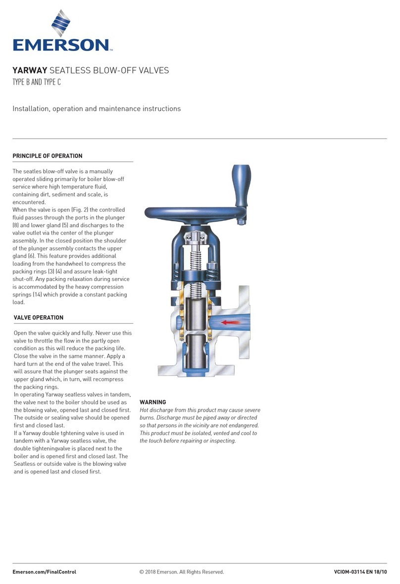
Emerson YARWAY B Manual
Emerson
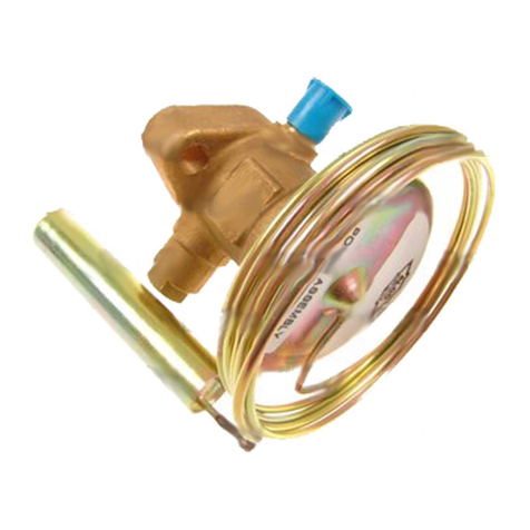
Emerson Alco Controls TCLE User manual
Emerson
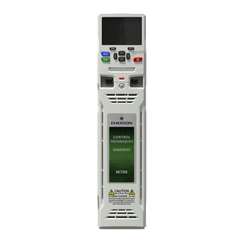
Emerson Unidrive M700 User manual

Emerson
Emerson Penberthy 500 Series Manual
Emerson
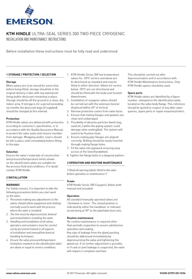
Emerson KTM Hindle 300 Series User manual

Emerson
Emerson ANDERSON GREENWOOD 4020HP Manual
Emerson
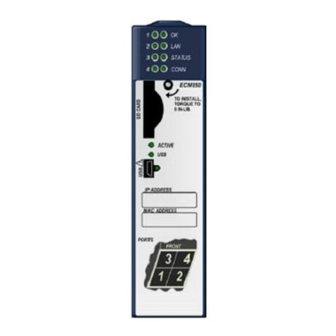
Emerson PACSystems RX3i IC695ECM850 User manual
Emerson
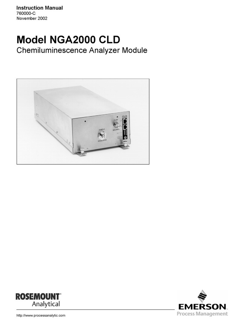
Emerson Rosemount Analytical NGA2000 CLD User manual
Emerson
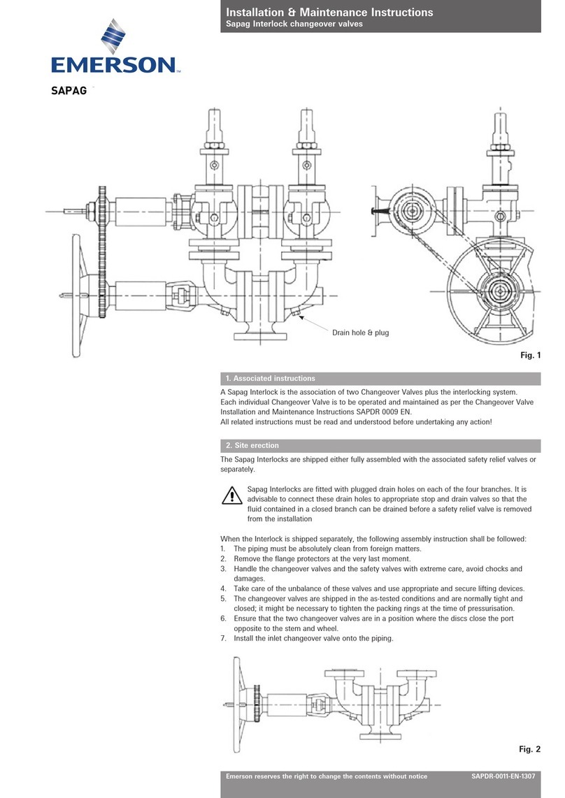
Emerson SAPAG Installation and operating instructions

Emerson
Emerson Anderson Greenwood 400 Series Quick guide
Emerson
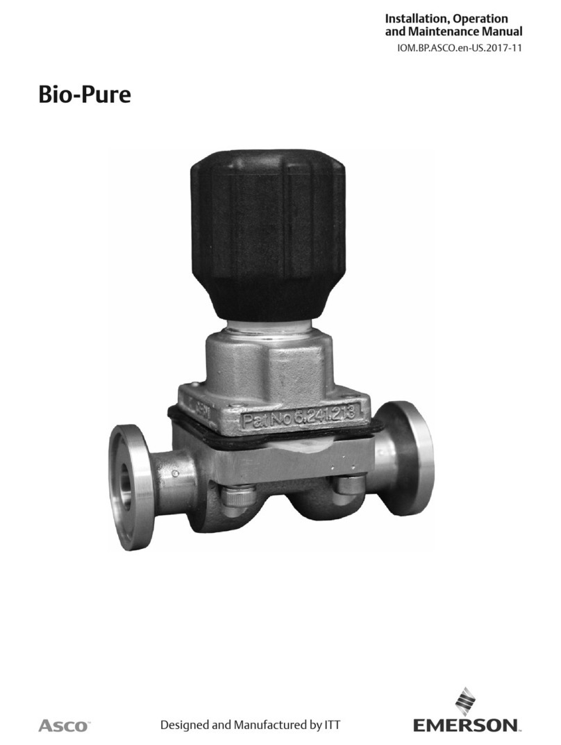
Emerson Asco Bio-Pure User manual
Emerson
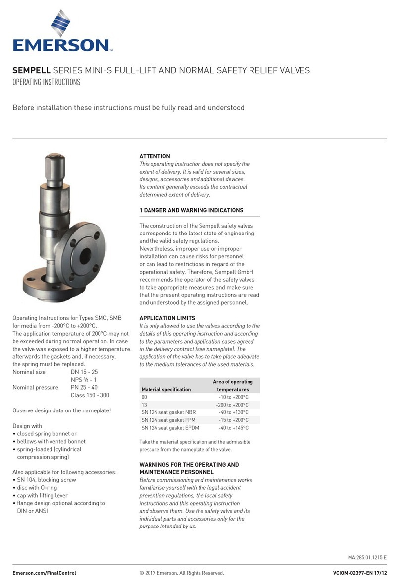
Emerson Sempell series User manual
Emerson
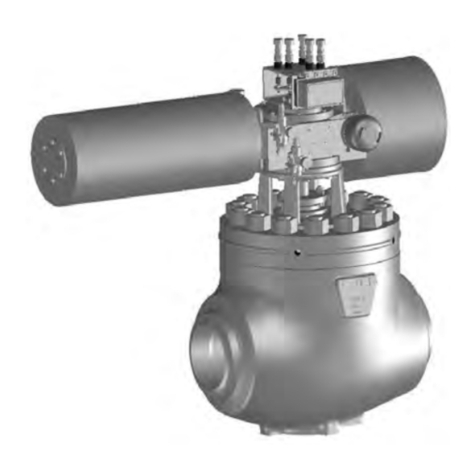
Emerson Fisher SS-264 User manual

Emerson
Emerson Fisher MR98LD User manual
Emerson
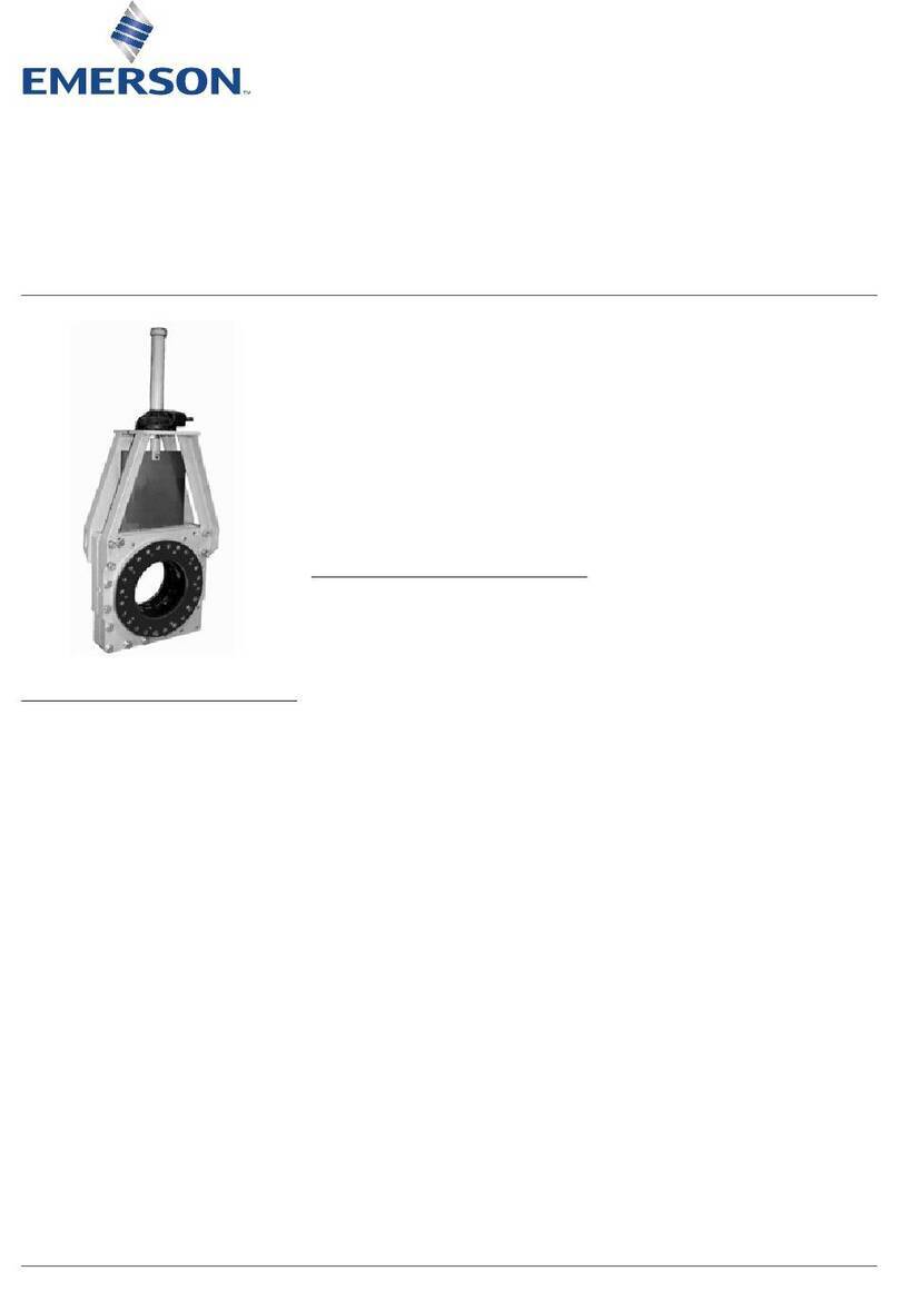
Emerson Clarkson series User manual
Emerson
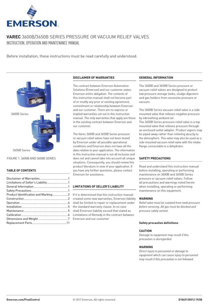
Emerson VAREC 3600B Series Operation and maintenance manual

Emerson
Emerson Bettis XTE3000 User manual

Emerson
Emerson Spence Type N6 User manual
Emerson
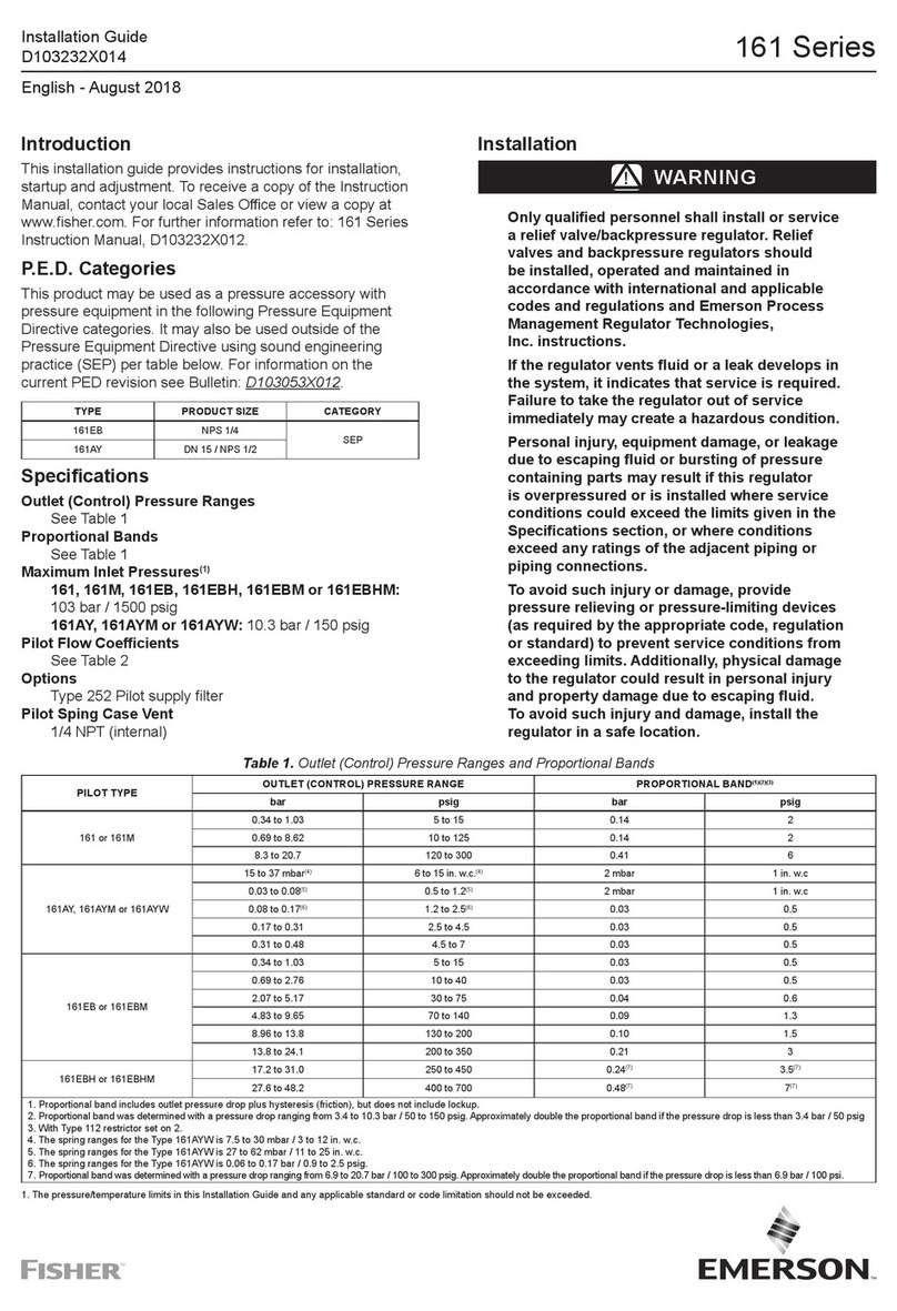
Emerson Fisher 161 Series User manual
Popular Control Unit manuals by other brands

Festo
Festo Compact Performance CP-FB6-E Brief description

Elo TouchSystems
Elo TouchSystems DMS-SA19P-EXTME Quick installation guide

JS Automation
JS Automation MPC3034A user manual

JAUDT
JAUDT SW GII 6406 Series Translation of the original operating instructions

Spektrum
Spektrum Air Module System manual

BOC Edwards
BOC Edwards Q Series instruction manual

KHADAS
KHADAS BT Magic quick start

Etherma
Etherma eNEXHO-IL Assembly and operating instructions

PMFoundations
PMFoundations Attenuverter Assembly guide

GEA
GEA VARIVENT Operating instruction

Walther Systemtechnik
Walther Systemtechnik VMS-05 Assembly instructions

Altronix
Altronix LINQ8PD Installation and programming manual

