manuals.online logo
Brands
  1. Home
  2. •
  3. Brands
  4. •
  5. Emerson
  6. •
  7. Control Unit
  8. •
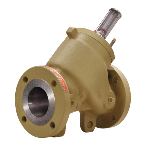
  9. Emerson Keystone Figure 637 Installation and operation manual

Emerson Keystone Figure 637 Installation and operation manual

This manual suits for next models

2

Other Emerson Control Unit manuals

Emerson Daniel 762 User manual

Emerson

Emerson Daniel 762 User manual

Emerson Fisher 63EGLP Series User manual

Emerson

Emerson Fisher 63EGLP Series User manual

Emerson FISHER NotchFlo DST User manual

Emerson

Emerson FISHER NotchFlo DST User manual

Emerson Rosemount Ultrasonic 3410 Series User manual

Emerson

Emerson Rosemount Ultrasonic 3410 Series User manual

Emerson Spence K3 User manual

Emerson

Emerson Spence K3 User manual

Emerson Fisher V270 User manual

Emerson

Emerson Fisher V270 User manual

Emerson Fisher 92C User manual

Emerson

Emerson Fisher 92C User manual

Emerson Neotecha Installation and operating instructions

Emerson

Emerson Neotecha Installation and operating instructions

Emerson FB1100 Parts list manual

Emerson

Emerson FB1100 Parts list manual

Emerson AVENTICS TV04-CV User manual

Emerson

Emerson AVENTICS TV04-CV User manual

Emerson Micro Motion User manual

Emerson

Emerson Micro Motion User manual

Emerson Anderson Greenwood 81P Technical specifications

Emerson

Emerson Anderson Greenwood 81P Technical specifications

Emerson Fisher 6010 User manual

Emerson

Emerson Fisher 6010 User manual

Emerson KTM Hindle 300 Series User manual

Emerson

Emerson KTM Hindle 300 Series User manual

Emerson AVENTICS 501 Series User manual

Emerson

Emerson AVENTICS 501 Series User manual

Emerson TopWorx PD200 Instruction manual

Emerson

Emerson TopWorx PD200 Instruction manual

Emerson Fisher 92B User manual

Emerson

Emerson Fisher 92B User manual

Emerson SW46 User manual

Emerson

Emerson SW46 User manual

Emerson YARWAY GS-1 User manual

Emerson

Emerson YARWAY GS-1 User manual

Emerson ANDERSON GREENWOOD PILOT 9300 Series User manual

Emerson

Emerson ANDERSON GREENWOOD PILOT 9300 Series User manual

Emerson Fisher V500 User manual

Emerson

Emerson Fisher V500 User manual

Emerson Fisher V150S Slurry Vee-Ball User manual

Emerson

Emerson Fisher V150S Slurry Vee-Ball User manual

Emerson KEYSTONE F635 Installation instructions

Emerson

Emerson KEYSTONE F635 Installation instructions

Emerson Anderson Greenwood 400 Series Quick guide

Emerson

Emerson Anderson Greenwood 400 Series Quick guide

Popular Control Unit manuals by other brands

Seitz 14A80 user manual

Seitz

Seitz 14A80 user manual

Wilo RS485 Installation and operating instructions

Wilo

Wilo RS485 Installation and operating instructions

Becker CentralControl CC41 Commissioning Instruction

Becker

Becker CentralControl CC41 Commissioning Instruction

SICK CDB650 operating instructions

SICK

SICK CDB650 operating instructions

Panduit NetKey NKP5E88M Series installation instructions

Panduit

Panduit NetKey NKP5E88M Series installation instructions

MX Options Concentric Petite Fitting instructions

MX

MX Options Concentric Petite Fitting instructions

Clean Water Systems Fleck 2510 Installation & start?up guide

Clean Water Systems

Clean Water Systems Fleck 2510 Installation & start?up guide

Fairchild FSB44104A user guide

Fairchild

Fairchild FSB44104A user guide

LEGRAND Wattstopper LMIN-104 installation instructions

LEGRAND

LEGRAND Wattstopper LMIN-104 installation instructions

PMK ATT10BNCS instruction manual

PMK

PMK ATT10BNCS instruction manual

Tektronix TDS3FFT user manual

Tektronix

Tektronix TDS3FFT user manual

Woodward easYgen Technical manual

Woodward

Woodward easYgen Technical manual

Balluff BNI EIP-502-105-R015 user guide

Balluff

Balluff BNI EIP-502-105-R015 user guide

NXP Semiconductors TWR-LS1021A Getting started

NXP Semiconductors

NXP Semiconductors TWR-LS1021A Getting started

Advantech PCM-3117 Startup manual

Advantech

Advantech PCM-3117 Startup manual

Danfoss MCO 101 manual

Danfoss

Danfoss MCO 101 manual

Moons' Lin Engineering R701P user manual

Moons'

Moons' Lin Engineering R701P user manual

Aventics RV1 operating instructions

Aventics

Aventics RV1 operating instructions

manuals.online logo
manuals.online logoBrands
  • About & Mission
  • Contact us
  • Privacy Policy
  • Terms and Conditions

Copyright 2025 Manuals.Online. All Rights Reserved.

© 2017 Emerson. All Rights Reserved.Emerson.com/FinalControl
KEYSTONE FIGURE 634/637 AND 638 SLURRY VALVES
INSTALLATION AND COMMISSIONING INSTRUCTIONS
Complete installation and commisioning for:
F634 (light duty slurry valves), F637 (medium duty slurry valves) and F638 (heavy duty slurry valves)
VCIOM-02445-EN 15/08
INSTALLATION INSTRUCTIONS
1. Ensure that the flanges are clean,
undamaged and compatible with the valve.
2. Spread the flanges to allow sufficient
clearance for the valve and gaskets.
DO NOT USE THE VALVE AS A CROWBAR.
3. Loosely fit two bolts at the bottom of the
flanges to bear the weight of the valve.
Note: F638 300 - 600 mm use short flange
bolts, for F634, F637 and F638 40 - 250 mm
use thru bolts.
GENERAL
The F634 and F637 are bi-directional valves and
will control flow in either direction.
The F638 40 - 300 mm is a uni-directional valve
and will only control flow in one direction.
The F638 350 - 600 mm is a bi-directional valve
and will control flow in either direction.
In most horizontal pipe installations it is
recommended that the valve be installed with
its shaft horizontal and the lower disc edge
opening downstream, particularly on slurry
or sedimentary duties. Flange gaskets are
required to ensure effective sealing. Check that
the gasket material is suitable for the service.
SAFETY PRECAUTIONS
For safety reasons, it is important to take the
following precautions before working on the
valve.
1. Ensure that the procedures below meet or
agree with the site procedures, if not review
with your site safety officers.
2. Personnel making any adjustments to
the valve arrangement should utilize all
necessary equipment and clothing normally
used to work with the process where the
valve is installed.
3. The line must be depressurized, drained and
vented before installing or maintenance on
the valve.
4. Handling and installation of all valves,
operators and actuators must be carried
out by personnel trained in all aspects
of installation and manual/mechanical
handling techniques using site occupational
health and safety procedures.
STORAGE INSTRUCTIONS
The valve faces should be adequately protected
against damage and coated with corrosion
inhibitor even when stored under cover.
FLANGE AND PIPE COMPATIBILITY
Emerson valves are suitable for installation into
most piping systems.
The standard end connections are:
F638 - Flanged ASME Class 150, 300, 600
F634, F637 - Flanged ASME Class 150
Refer valve literature sheet for standard
drillings.
Weld neck flanges (flange ID approximates
valve bore) are recommended to ensure
maximum valve performance. However slip on
flanges may be used.
NOTE
These valves are not recommended for dead
end service.
4. For F638 40 - 300 mm check that the flow
arrow on the side of the valve agrees with
the direction of flow. (Longest end of the
valve must face downstream).
5. Insert the valve between the flanges with
gaskets either side.
6. Loosely fit the remainder of the flange
bolts.
7. Center the valve and ensure the gaskets
are properly positioned.
8. Hand tighten all the flange bolts.
9. Open the valve fully and check that the
valve cycles correctly. (The disc is in line
with the parallel flats or keyway in the
stem).
10. Cross tighten all the flange bolts.
(Seeflange diagram for tightening
sequence and bolt torque table for
torques).
11.
After the pipeline is pressurized, check
for flange leaks and adjust the gland as
necessary.
5. Ensure the valve pressure/temperature
limitations marked on the name plate
comply with the service application.
6. When used for line fluids with a temperature
of 80°C or higher, the valve body can
become very hot and should not be handled
without appropriate protection.
7. Do not weld near the valve, as this will result
in serious damage to the valve.
2
0038
0038
A
½ UNC 89 120 ½ UNC 29 39
⅝ UNC 119 161 ⅝ UNC 57 77
¾ UNC 211 286 ¾ UNC 99 134
⅞ UNC 338 458 ⅞ UNC 158 214
1 UN8 485 657 1 UN8 236 320
1⅛ UN8 716 970 1⅛ UN8 339 459
1¼ UN8 1042 1412 1¼ UN8 468 634
1⅜ UN8 1414 1917 1⅜ UN8 625 848
1½ UN8 1863 2525 1½ UN8 816 1107
1⅝ UN8 2398 3251 1⅝ UN8 1044 1416
1¾ UN8 3030 4108 1¾ UN8 1301 1764
1⅞ UN8 3512 4761 1⅞ UN8 1602 2172
2 UN8 4218 5718 2 UN8 1949 2643
CE I.D. plate
KEYSTONE FIGURE 634/637 AND 638 SLURRY VALVES
INSTALLATION AND COMMISSIONING INSTRUCTIONS
Valve I.D. plate
NAME PLATES
All Emerson valves will be tagged with a valve I.D. plate. All PED certified valves will also be
tagged with a CE I.D. plate. See diagram.
Note: Example tags, data is typical only.
NOTES
1. Above torques are based on B7/2H, L7/GR4 and B16/GR4 stud bolts/nuts only to produce 60% of
the yield stress.
2. Please contact a Emerson sales representative prior to using anything other than the above torque values
on stud bolts B7 and B16.
Valve description
Flange
drilling
Pressure rating
CE Autorisation number
Valve trim code
Max working pressure
Max/min temperature
Valve serial number
Year of manufacture
F638 valve shown Typical flange showing tightening sequence
BOLT TORQUES FOR LUBRICATED AND PTFE COATED BOLTS
Lubricated B7/2H, L7/GR4 PTFE coated B7/2H, L7/GR4, B16/GR4
Stud size Torque Stud size Torque
inches lbf·ft Nm inches lbf·ft Nm
3
KEYSTONE FIGURE 634/637 AND 638 SLURRY VALVES
INSTALLATION AND COMMISSIONING INSTRUCTIONS
Neither Emerson, Emerson Automation Solutions, nor any of their affiliated entities assumes responsibility for the selection, use or maintenance of any product.
Responsibility for proper selection, use, and maintenance of any product remains solely with the purchaser and end user.
Keystone is a mark owned by one of the companies in the Emerson Automation Solutions business unit of Emerson Electric Co. Emerson Automation Solutions, Emerson
and the Emerson logo are trademarks and service marks of Emerson Electric Co. All other marks are the property of their respective owners.
The contents of this publication are presented for informational purposes only, and while every effort has been made to ensure their accuracy, they are not to be
construed as warranties or guarantees, express or implied, regarding the products or services described herein or their use or applicability. All sales are governed by
our terms and conditions, which are available upon request. We reserve the right to modify or improve the designs or specifications of such products at any time without
notice.
Emerson.com/FinalControl
ACTUATOR MOUNTING INSTRUCTIONS
The Keystone F79U pneumatic actuator is
mounted directly to the valve to top plate with
four studs, nuts and washers. The actuator is
normally installed parallel to the pipeline. Other
actuators may require mounting brackets.
1. Ensure that the valve and actuator are in the
fully closed position (the drive shaft keyway
perpendicular to the actuator piston-
cylinder axis). The valve shaft flats should
be parallel to the disc and the keyway in line
with the disc.
2. Check that the actuator mounting studs
are tightly installed in the actuator housing.
(On models with two mounting bolt circles,
check that the mounting studs correspond
to the valve top plate mounting holes).
3. Install a lockwasher and nut on each
mounting stud and tighten.
4. Connect an appropriate air supply to the
actuator, this unit normally requires a
550kPa clean, dry air supply.
5. The Keystone F79U pneumatic actuator
is factory lubricated and requires no
maintenance.
MAINTENANCE
The gland will require periodic checking.
Ifgland leakage occurs, tighten gland nuts (A)
equally until leaking ceases. No lubrication
is required. Do not over tighten as this could
result in breakage.