manuals.online logo
Brands
  1. Home
  2. •
  3. Brands
  4. •
  5. Emerson
  6. •
  7. Control Unit
  8. •
  9. Emerson Fisher H200 Series User manual

Emerson Fisher H200 Series User manual

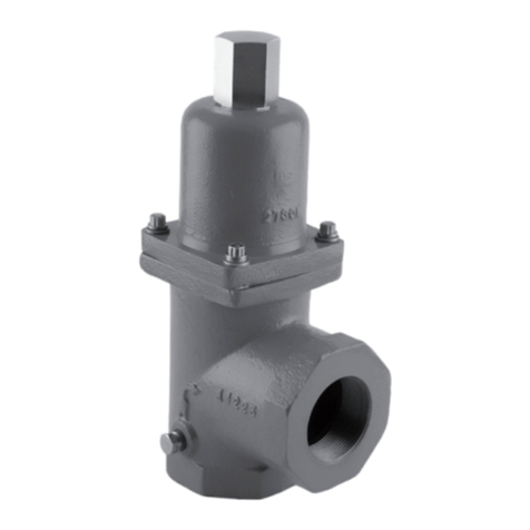
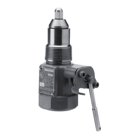
Figure 1. H200 Series Relief Valve
H200 Series External Relief Valves
▲ WARNING
Failure to follow these instructions or
to properly install and maintain this
equipment could result in an explosion,
fire and/or fire causing property damage
and personal injury or death.
Fisher™ relief valves must be installed,
operated and maintained in accordance
with federal, state and local codes, rules
and regulations and Emerson Process
Management Regulator Technologies Inc.
(Emerson) instructions.
A person should never stand directly
over or in front of or look directly into a
relief valve when the tank is pressurized.
The relief valve could suddenly “pop”
open blowing gas, dirt and other debris
into the person’s face and eyes.
Call a qualified service person to service
the unit. Installation, operation and
maintenance procedures performed
by unqualified person may result
in improper adjustment and unsafe
operation. Either condition may result in
equipment damage or personal injury.
Only a qualified person shall install or
service the relief valve.
Introduction
Scope of the Manual
This manual provides specications, installation,
maintenance instructions and parts ordering
information for the H200 Series.
Only personnel qualied through training or experience
should install, operate and maintain this relief valve. If
there are any questions concerning these instructions,
contact your local Emerson Impact Partner O󰀩ce
before proceeding.
Product Description
The H200 Series Pop™ relief valves, Figures 1 and 2,
are self-operated relief valves with preset and pinned
spring retainers. The inlet pressure registers directly
on a spring opposed poppet assembly which includes
a Nitrile (NBR) disk. When the inlet gas pressure
increases above the spring setting, the poppet and disk
assembly is pushed away from the orifice. Springs
are available that provide any relief pressure setting
from 25 to 300 psig / 1.7 to 20.7 bar.
With this simple operation and wide spring setting
selection, the H200 Series Pop relief valves
may be used where venting to atmosphere is
acceptable, where the process gas is compatible
with the Nitrile (NBR) disk, where its relief capacity
is adequate and where some pressure relieving
tolerance is acceptable. Common applications
include use on pneumatic control lines of air drills,
jackhammers and other similar equipment and on
farm tap installations. The H200 Series is comprised
of the Types H202 and H203 relief valves with the
di󰀨erence being in the inlet connection size.
Instruction Manual
D104657X012
August 2023
H200 Series
Specifications
This section lists the specications for H200 Series external relief valves. Factory specications are engraved on
the body of the relief valve at the factory.
Available Configuration and End Connections
Type H202: 3/4 NPT connection
Type H203: 1 NPT connection
Maximum Allowable Relief (Inlet) Pressure(1)
400 psig / 27.6 bar
Relief Pressure Ranges(1)
See Tables 1 and 2
Flow Capacity
See Table 2
Construction Materials
Body, Poppet and Spring Retainer: Brass
Disk: Nitrile (NBR)
Spring: 302 Stainless steel
Temperature Capabilities(1)
-20 to 160°F / -29 to 71°C
Approximate Weight
0.5 lbs / 0.2 kg
Option
Type P145 raincap
1. The pressure/temperature limits in this Instruction Manual and any applicable standard or code limitation should not be exceeded.
Table 1. Relief Pressure Spring Ranges
RELIEF PRESSURE SETTINGS SPRING
PART NUMBER SPRING COLOR RELIEF SETTING TOLERANCE
psig bar psig bar
25 to 30 1.7 to 2.1 1H485637022 Pink ±5 ±0.34
31 to 55 2.1 to 3.8 1J152137022 White
56 to 70 3.9 to 4.8 1P391137022 Blue
±8 ±0.5565 to 95 4.5 to 6.5 T1049037022 Plain
90 to 130 6.2 to 9.0 1F791337022 Purple
131 to 160 9.0 to 11.0 1F7912T0012 Yellow
±15 ±1.03
161 to 190 11.1 to 13.1 T12699T0012 Green
191 to 235 13.2 to 16.2 1F790937022 Brown
236 to 300 16.3 to 20.7 1E954637052 Plain
Table 2. Relief Set Pressures and Capacities
RELIEF SET PRESSURE(1) SET PRESSURE PLUS BUILD-UP FLOW CAPACITY(2)
psig bar psig bar SCFH Nm3/h
25 1.7 50 3.4 34,200 916
50 3.4 75 5.2 47,400 1270
75 5.2 100 6.9 60,000 1608
100 6.9 120 8.3 69,600 1865
125 8.6 150 10.3 83,400 2235
150 10.3 180 12.4 100,500 2693
175 12.1 210 14.5 117,600 3152
200 13.8 240 16.5 132,000 3538
225 15.5 270 18.6 150,000 4020
250 17.2 300 20.7 165,000 4422
275 19.0 330 22.7 180,000 4824
300 20.7 360 24.8 195,000 5226
1. This is the initial leak point, the point at which the relief valve begins to discharge.
2. 0.6 Specific Gravity Gas. To convert to equivalent capacities of other gases, multiply the table values by 0.775 for air or 0.789 for nitrogen. Multiply the flow obtained by 0.0268 to convert
to (Nm3/h) at 0°C and 1.01 bar.
2
H200 Series
Figure 2. H200 Series Operational Schematics
W0120_1
Principle of Operation
The relief valve (See Figure 1) is held close by the
spring force seating the rubber valve disc against
the orifice.
When the tank pressure exceeds the spring force, the
valve disc lifts off the orifice allowing gas to discharge
through the valve to the air.
Gas discharge initially may be small producing only
seepage and a light “hissing” sound. As pressure
increases and gas volume discharge continues, a
“popping” condition occurs with large volumes of gas
discharge and a loud “hissing or roaring” sound.
When the tank pressure decreases enough, the
spring force closes the valve disc back against the
orifice stopping further discharge
Installation
▲ WARNING
Vapor relief valves must be installed
only in the vapor space to provide relief
capacity for the tank.
This relief valve may be installed in any position but
must be oriented so that gas discharged from the
valve does not create a re, toxic or explosion hazard.
The relief valve should be protected from material and
conditions that could clog the outlet side of the valve
and a󰀨ect the venting of gas.
A typical installation is shown in Figure 3. A Type P145
raincap is recommended for use with any H200 Series
relief valve.
The relief valve and installation should be checked for
compliance with all applicable codes.
Maintenance
Safety relief valves are non-repairable valves and
cannot be adjusted in the field.
▲ WARNING
Any valve that has fully opened “popped”
should be tested to see if it is within the
allowable start-to-discharge pressure
setting. If it is not within the correct
range, it must be replaced. Relief
valve start-to-discharge and reseat
pressures may be lower if the valve has
fully opened (popped).
It is recommended that all relief valves be regularly
inspected for visible damage, dirt, corrosion, missing
raincaps, paint inside outlet, tampering, etc. If any of
the preceding is evident or questionable, the valve
should be re-tested or replaced immediately.
The discharge side of the relief valve body must be
kept free of dirt, water and other foreign matter which
can damage the valve seat or “weld” some “wing style”
poppets to the valve body. This can prevent the valve
from opening. Replace valves when this occurs.
H200 SERIES
RELIEF VALVE
TYPE P145 RAIN CAP
LOW-PRESSURE
REDUCING REGULATOR
HIGH-
PRESSURE
REDUCING
REGULATOR
INLET PRESSURE
Figure 3. Typical Farm Tap Installation
AF9930-C
A1619-1
3
H200 Series
D104657X012 © 2023 Emerson Process Management Regulator
Technologies, Inc. All rights reserved. 08/23.
The Emerson logo is a trademark and service mark of Emerson Electric
Co. All other marks are the property of their prospective owners.
Fisher™ is a mark owned by Fisher Controls International LLC, a business
of Emerson Automation Solutions.
The contents of this publication are presented for informational purposes
only, and while every e󰀨ort has been made to ensure their accuracy,
they are not to be construed as warranties or guarantees, express or
implied, regarding the products or services described herein or their use
or applicability. All sales are governed by our terms and conditions, which
are available upon request. We reserve the right to modify or improve the
designs or specications of such products at any time without notice.
Emerson Process Management Regulator Technologies, Inc does not
assume responsibility for the selection, use or maintenance of any
product. Responsibility for proper selection, use and maintenance of any
Emerson Process Management Regulator Technologies, Inc. product
remains solely with the purchaser.
Parts Ordering
When corresponding with your local Sales Office
about this relief valve, include the type number,
serial number and other information stamped on
the nameplate.
When ordering replacement parts, reference the key
number of each needed part and specify the eleven
character part number as found in the following
parts list.
Parts List
Key Description Part Number
1 Body
2 Spring Retainer
3 Groove Pin
4* Spring
5 Poppet Assembly
H200 Series
Facebook.com/EmersonAutomationSolutions
LinkedIn.com/company/emerson-automation-solutions
Twitter.com/emr_automation
[email protected]
Fisher.com
Emerson Automation Solutions
Americas
McKinney, Texas 75070 USA
T +1 800 558 5853
+1 972 548 3574
Europe
Bologna 40013, Italy
T +39 051 419 0611
Asia Pacic
Singapore 128461, Singapore
T +65 6777 8211
Middle East and Africa
Dubai, United Arab Emirates
T +971 4 811 8100

Other Emerson Control Unit manuals

Emerson KTM Series Quick guide

Emerson

Emerson KTM Series Quick guide

Emerson Rosemount 68 Series User manual

Emerson

Emerson Rosemount 68 Series User manual

Emerson Daniel 700 Series User manual

Emerson

Emerson Daniel 700 Series User manual

Emerson Fisher 6010 User manual

Emerson

Emerson Fisher 6010 User manual

Emerson Alco Controls CVE-014 User manual

Emerson

Emerson Alco Controls CVE-014 User manual

Emerson Alco Controls 110RB User manual

Emerson

Emerson Alco Controls 110RB User manual

Emerson numatics E22 User manual

Emerson

Emerson numatics E22 User manual

Emerson Fisher Design GX Series User manual

Emerson

Emerson Fisher Design GX Series User manual

Emerson EX4-6-...FLR Series User manual

Emerson

Emerson EX4-6-...FLR Series User manual

Emerson HF User manual

Emerson

Emerson HF User manual

Emerson Fisher Large ED User manual

Emerson

Emerson Fisher Large ED User manual

Emerson Yarway 7100 Series User manual

Emerson

Emerson Yarway 7100 Series User manual

Emerson Enardo ES-800 Series User manual

Emerson

Emerson Enardo ES-800 Series User manual

Emerson Anderson Greenwood 93 Series User manual

Emerson

Emerson Anderson Greenwood 93 Series User manual

Emerson FISHER NotchFlo DST User manual

Emerson

Emerson FISHER NotchFlo DST User manual

Emerson Fisher POSI-SEAL A31A User manual

Emerson

Emerson Fisher POSI-SEAL A31A User manual

Emerson K-BALL F110 Quick guide

Emerson

Emerson K-BALL F110 Quick guide

Emerson Fisher Large ET User manual

Emerson

Emerson Fisher Large ET User manual

Emerson FASANI User manual

Emerson

Emerson FASANI User manual

Emerson Asco PV-MXX-272/374 Series User manual

Emerson

Emerson Asco PV-MXX-272/374 Series User manual

Emerson Fisher Type H800 User manual

Emerson

Emerson Fisher Type H800 User manual

Emerson Fisher N201 Series User manual

Emerson

Emerson Fisher N201 Series User manual

Emerson AVENTICS User guide

Emerson

Emerson AVENTICS User guide

Emerson Fisher Baumann Little Scotty 24000C User manual

Emerson

Emerson Fisher Baumann Little Scotty 24000C User manual

Popular Control Unit manuals by other brands

GRASS VALLEY KAMELEON Series instruction manual

GRASS VALLEY

GRASS VALLEY KAMELEON Series instruction manual

Whadda DS1302 user manual

Whadda

Whadda DS1302 user manual

Raritan I34M-1 Troubleshooting and Replacement

Raritan

Raritan I34M-1 Troubleshooting and Replacement

axing SKM 2-00 Operation manual

axing

axing SKM 2-00 Operation manual

Cepex PVC-U Series manual

Cepex

Cepex PVC-U Series manual

Volth ARGO HYTOS SD3E2X-C2 S5 Series operating instructions

Volth

Volth ARGO HYTOS SD3E2X-C2 S5 Series operating instructions

ZURN TEMP-GARD III Z7300-SS-MT-HW-H9 manual

ZURN

ZURN TEMP-GARD III Z7300-SS-MT-HW-H9 manual

Newhaven Display International NHD user guide

Newhaven Display International

Newhaven Display International NHD user guide

ADLINK Technology AVA-5500 Series user manual

ADLINK Technology

ADLINK Technology AVA-5500 Series user manual

Honeywell EXCEL CARE 5000 installation guide

Honeywell

Honeywell EXCEL CARE 5000 installation guide

SMC Networks XGT312-50336 Series Operation manual

SMC Networks

SMC Networks XGT312-50336 Series Operation manual

WNC M14A2A user manual

WNC

WNC M14A2A user manual

Graco Series A Instructions-parts list

Graco

Graco Series A Instructions-parts list

tams elektronik S88-6 manual

tams elektronik

tams elektronik S88-6 manual

Siemens SINAMICS S120 Equipment manual

Siemens

Siemens SINAMICS S120 Equipment manual

Nexta Tech TOP-ML/One instructions

Nexta Tech

Nexta Tech TOP-ML/One instructions

Monoprice RS-232 10761 Integration note

Monoprice

Monoprice RS-232 10761 Integration note

RF-Star RF-83SH manual

RF-Star

RF-Star RF-83SH manual

manuals.online logo
manuals.online logoBrands
  • About & Mission
  • Contact us
  • Privacy Policy
  • Terms and Conditions

Copyright 2025 Manuals.Online. All Rights Reserved.