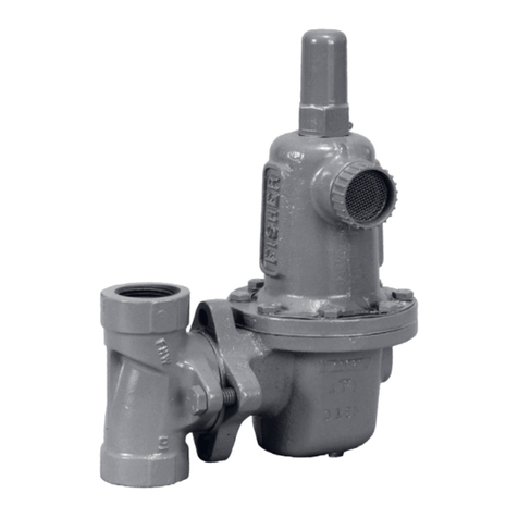
Types 95L, 95H, 95HP, and 95HT
6
change the outlet pressure, loosen the locknut (key 17,
Figure 3, 4, or 5) and turn the adjusting screw (key 15,
Figure 3, 4, or 5) clockwise to increase outlet pressure,
or counterclockwise to decrease it. Monitor the outlet
pressure with a test gauge during the adjustment.
Tighten the locknut to maintain the desired setting.
All regulator springs can be backed off to provide zero
outlet. Recommended outlet pressure ranges available,
maximum inlet pressures and temperatures, and color
codes of the respective springs are shown in Tables 1
and 2.
Close the upstream shutoff valve. Close downstream
shutoff valve. Open bleed valve between the regulator
and the downstream shutoff valve. Without changing
regulator spring adjustment, all pressure between
the upstream and downstream shutoff valves will be
released through the bleed valve, since the Type 95L
or 95H regulator opens in response to the decreased
outlet pressure.
!
Warning
Due to normal wear that may occur, parts must be
periodically inspected and replaced if necessary. The
frequency of inspection depends on the severity of
service conditions. This section includes instructions
for disassembly and replacement of parts. All key
numbers refer to Figures 3, 4, and 5.
1. Unscrew the valve plug guide (key 5) from the
body (key 1). The valve plug spring (key 10) and
the valve plug (key 4) will normally come out of
the body along with the valve plug guide. On
NPS 1-1/2 or 2 (DN 40 or 50) units the stem
(key 6, Figure 5) will also come out of the
regulator body.
2. Inspect the seating surface of the valve plug
(key 4), make sure that the elastomer, PTFE or
polished metal surface of the valve plug is not
damaged. Replace if damage is noted.
3. Inspect the seating edge of the orice (key 3). If
damage is noted, unscrew the orice from the
body and replace it with a new part. Torque per
Table 3. If no further maintenance is required,
reassemble the regulator in the reverse of the
above steps. When installing the valve plug guide
(key 5) coat the threads and sealing surface with
sealant to ensure an adequate metal-to-metal
seal. Reassembly torque per Table 3.
4. If diaphragm damage is suspected, or to inspect
the diaphragm or other internal parts, loosen the
locknut (key 17) and turn the adjusting screw
(key 15) to remove all spring compression.
Steps 5 and 6 apply to Type 95L and sizes NPS 1/4
to 1 (DN 25) of the 95H Series. If the unit being
disassembled is an NPS 1-1/2 to 2 (DN 40 and 50)
size Type 95H, HP, or HT, proceed to steps 7
and 8.
5. Remove the diaphragm case cap screws (key 16)
and lift off the spring case (key 2). Remove the
upper spring seat (key 9) and regulator spring
(key 11). On NPS 1/4 to 1 (DN 25) sizes
Type 95H units only, remove the lower spring seat
(key 8). On Type 95L units, remove the diaphragm
head assembly (key 21).
6. Remove the diaphragm(s) and examine for
damage. Replace if damage is noted. Note
that if the diaphragm is metal, two diaphragms
should be used except for Type 95L, NPS 1/4
with 2 to 6 psi (0,14 to 0,41 bar) spring range
which uses only one metal diaphragm.
7. Remove the diaphragm-diaphragm head
assembly. It can be disassembled for inspection
of the diaphragm (key 12) and two small
diaphragm gaskets (key 47) or O-ring (key 45).
Remove the locknut (key 31) from the pusher
post (key 30) and separate the assembly. An
O-ring is used to seal around the pusher post if
an elastomer diaphragm is used, and the gaskets
are used with stainless steel diaphragm(s).
8. Unscrew and remove the stem guide bushing
(key 7). An O-ring (key 51) held in place by the
packing follower (key 50) can then be examined
for damage.
9. With diaphragm(s) removed, check to be sure
the pressure registration hole (pitot tube, key 20, in
NPS 3/4 (DN 20) and larger sizes) is completely
open and free of all obstructions.
10. If the unit has metal diaphragms,
a. (Applicable only for the lower diaphragm
head of Type 95H/HT, NPS 1-1/2 to 2)

