Type Y693
4
Startup and Adjustment
To avoid personal injury, property dam-
age, or equipment damage caused by
bursting of pressure containing parts or
explosion of accumulated gas, never
adjust the control spring to produce an
outlet pressure higher than the upper
limit of the outlet pressure range or that
particular spring (see table 1). If the
desired outlet pressure is not within the
range of the control spring, install a
spring of the proper range according to
the diaphragm and spring case area
section of the maintenance procedure.
With installation completed, the regulator can be placed
in operation by slowly opening the upstream and
downstream block valves, if used, while using gauges
to monitor pressure. The regulator takes control when
downstream pressure is established.
The regulator has been adjusted at the factory to
provide approximately the reduced pressure requested.
To ensure the correct pressure setting always use a
pressure gauge to verify the outlet pressure setting. The
range of allowable pressure settings is stamped on the
spring casing nameplate. If a pressure setting beyond
the stamped range is required, install a spring with the
desired range by following the procedures for changing
the spring and diaphragm in the Maintenance section.
To adjust the pressure setting, perform the following
steps (key numbers are referenced in figures 3, 4 & 5):
1. Remove the closing cap (key 3, if required).
2. Turn the adjusting screw (key 2) either clockwise to
increase outlet pressure or counterclockwise to de-
crease outlet pressure. The regulator will go into imme-
diate operation. To ensure correct operation always use
a pressure gauge to monitor the blanket pressure when
making adjustments.
3. Replace the closing cap (key 3, if required).
Shutdown
First, close the nearest upstream shutoff valve and
then, close the nearest downstream shutoff valve and
the block valve on the control line (refer to figure 2).
Next, open the vent valve between the regulator and
the downstream shutoff valve nearest to it. Then, open
the upstream vent valve and the vent valve in the
control line. All pressure between these shutoff valves
is released through the open vent valves, since a gas
blanketing regulator remains open in response to the
decreasing downstream pressure. If vent valves are not
installed, safely bleed off both inlet and outlet pressures,
and check that the regulator contains no pressure.
Principle of Operation
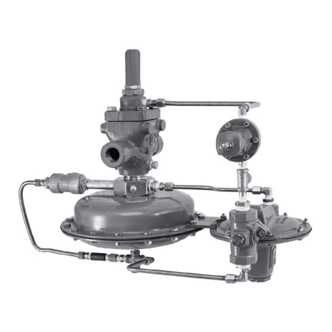
The Type Y693 Gas Blanketing Regulator reduces a
higher pressure gas to maintain a positive low pressure
of blanket gas over a stored liquid (see figure 2). Also
when the vessel (or tank) is suddenly cooled, causing
vapors to contract, the regulator replaces the volume of
contracting vapors with a volume of blanketing gas to
prevent the internal vessel pressure from decreasing. In
both cases, a positive vessel pressure prevents
outside air from entering the vessel and reduces the
possibility of atmospheric pressure collapsing the
vessel.
Gas blanketing regulators respond to a slight decrease in
internal vessel pressure (caused by pumpout or atmo-
spheric cooling) by throttling open to increase the flow
rate of gas into the vessel. When the vessel’s liquid level
has been lowered to the desired point and the vapor
pressure reestablished, the regulator throttles closed.
When the liquid level drops and vessel pressure de-
creases below the setting of the control spring, the
spring force on the diaphragm opens the disk assembly
to supply the required flow of gas to the vessel. When
vessel pressure has been satisfied, outlet pressure
tends to increase slightly, acting on the diaphragm. When
the outlet pressure exceeds the control spring setting,
the diaphragm moves to close the disk assembly.
Maintenance
Regulator parts are subject to normal wear and must be
inspected and replaced as necessary. The frequency of
inspection and replacement of parts depends upon the
severity of service conditions or the requirements of
local, state, and federal regulations. Due to the care
Fisher takes in meeting all manufacturing requirements
(heat treating, dimensional tolerances, etc.), use only
replacement parts manufactured or furnished by Fisher.
To avoid personal injury, property dam-
age, or equipment damage caused by
sudden release of pressure, isolate the
regulator from all pressure and cau-
tiously release trapped pressure from the
regulator before attempting disassembly.
