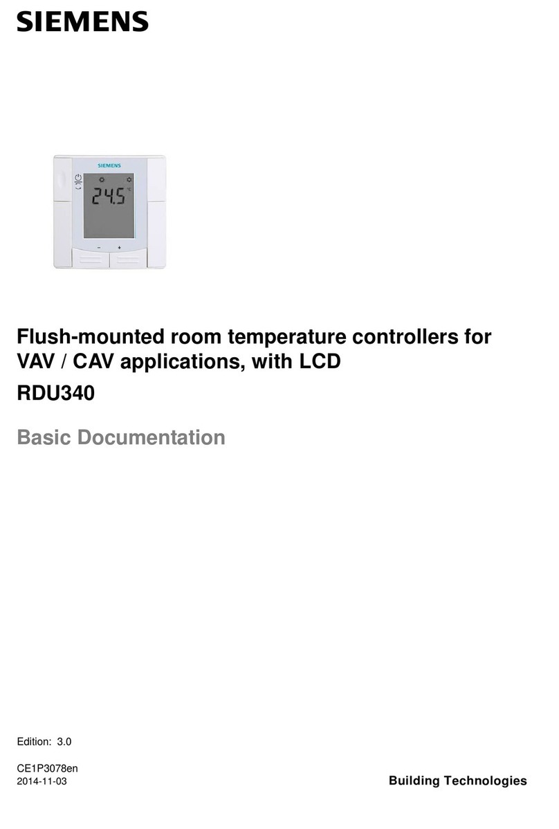
Cleco mPro400GCD-M User manual

For additional product information visit our website at www.ClecoTools.com
Hardware Description
P2309HW
2019-08
mPro400GCD-M
Global Controller Master

P2309HW |
2019-08 Apex Tool Group
Copyright © Apex Tool Group, 2019
No part of this document may be reproduced in any way or in any form, in whole or in part, or in a
natural or machine-readable language, or transmitted on electronic, mechanical, optical, or other
media, without the express permission of the Apex Tool Group.
Disclaimer
The Apex Tool Group reserves the right to modify, supplement, or improve this document or the
product without prior notice.
Trademark
Cleco is a registered trademark of Apex Brands, Inc.
Apex Tool Group GmbH
Industriestraße 1
73463 Westhausen
Germany

Apex Tool Group
P2309HW |
2019-08 3
INT
Contents
EN
1 Notes on this Description ..................................................................... 5
2 Safety ................................................................................................... 5
3 Product description............................................................................... 9
4 Technical Specifications ....................................................................... 9
5 Pin Assignment................................................................................... 10
6 Storage Access .................................................................................. 12
7 Items Delivered .................................................................................. 12
DE
1 Zu dieser Beschreibung ..................................................................... 13
2 Sicherheit ........................................................................................... 13
3 Produktbeschreibung ......................................................................... 17
4 Technische Daten............................................................................... 17
5 Steckerbelegung ................................................................................ 18
6 Speicherzugänge ............................................................................... 20
7 Lieferumfang ...................................................................................... 20
ES
1 Acerca de esta descripción del hardware .......................................... 21
2 Seguridad ........................................................................................... 21
3 Descripción del producto.................................................................... 25
4 Especificaciones técnicas .................................................................. 25
5 Asignación de enchufes ..................................................................... 26
6 Acceso a memoria.............................................................................. 28
7 Volumen de suministro ....................................................................... 28

4 P2309HW |
2019-08 Apex Tool Group
INT FR
1 À propos de cette description du matériel........................................... 29
2 Sécurité............................................................................................... 29
3 Description du produit ......................................................................... 33
4 Caractéristiques techniques................................................................ 33
5 Disposition des connecteurs ............................................................... 34
6 Accès à la mémoire, mémoire portable .............................................. 36
7 Volume de livraison............................................................................. 36
PL
1 Informacje dotyczące tego opisu ........................................................ 37
2 Bezpieczeństwo .................................................................................. 37
3 Opis produktu...................................................................................... 41
4 Dane techniczne ................................................................................. 41
5 Rozkład wyprowadzeń ........................................................................ 42
6 Dostępy do pamięci ............................................................................ 44
7 Zakres dostawy................................................................................... 44
INT
8 System .................................................................................................45
9 Connections .........................................................................................46
10 Dimensions ..........................................................................................47

Apex Tool Group P2309HW | 2018-09 5
1
EN
1Notes on this Description
The information contained within this document is intended
fro all individuals responsible for connecting and installing
the controller.
Software instructions are provided in separate program-
ming manuals based upon the version installed.
The original language of this document is German.
Minimum Software Requirements
Additional Document References
Important Symbols
2 Safety
2.1 General Requirements
Only operate the controller after reading and fully
understanding this document. Failure to follow the
directions and safety instructions could result in elec-
tric shocks, burns and/or serious injuries.
Keep this document in a safe place for future refer-
ence! These safety instructions must be accessible all
personnel programming, operating or repairing the
controller.
2.2 Intended Use
The controller is a part of the Cleco Production Tools Tight-
ening System and is intended exclusively for industrial use
in fastening processes. Only use the controller under the
following conditions:
• In accordance with the components listed in the EC
Declaration of Conformity.
• Identified environmental conditions; see relevant docu-
mentation.
• Appropriate supply voltage; reference respective docu-
mentation.
• In EMC Limit Class A (electromagnetic immunity for
industrial areas). For the currently observed EMC
standards, see the EC Declaration of Conformity.
2.3 Predictable Misuse
Do not use the controller:
• In potentially explosive areas.
• In damp locations or outdoors.
• In combination with cutting tools (drills, milling cutters,
grinders…).
• In non-industrial applications (eg residential area).
• For fastening applications not mentioned in the decla-
ration of conformity.
• If safety devices are being over-written.
2.4 Operator Training
The tightening system may only be put into operation,
adjusted and tested by qualified and trained personnel.
Personnel must be instructed by qualified employees of
Apex Tool Group.
The controller has been preset by Apex Tool Group.
Adjustmenty of the controller to accommodate special
requirements may only be carried out by a qualified per-
son1).
Additional information are available in the Programming
Manual.
No. Description
S168813
V1.8.0
Standard Controller Software
S168677 mProRemote – Interface software between an
external computer and controller
No. Document type
P1730E Reference Handbook
Fastening Sequences
P2279SB Systemhandbook NeoTek
P2361JH Quick Installation Guide Global Controller
P2280PM Programming Manual
mPro400GCD Standard SW
P3307C EC Declaration of Conformity
mPro400GCD-M
Italic Identifies menu options), input fields, control
boxes, options fields or dropdown menus.
> Denotes the selection of a menu option from
a menu, e.g. File > Print
<…> Denotes switches, pushbuttons or keys of an
external keyboard, e.g. <F5>
Courier Denotes filenames and paths, e.g.
setup.exe
• Denotes lists, level 1
- Denotes lists, level 2
a)
b)
Denotes options
→ Denotes results
1. (…)
2. (…)
Denotes action steps in sequence
Denotes a single action step
Sales &
Service
Centers
Cleco Production Tools – Sales & Service
Centers, see last page.
1.) Due to their training, knowledge, experience and understand-
ing of the circumstances involved in this kind of work, suitably qual-
ified personnel are able to identify potential hazards and to initiate
appropriate safety measures. Qualified personnel are obliged to
comply with regulations.

6 P2309HW | 2018-09 Apex Tool Group
1
EN 2.5 Personal Protective Equipment
(PPE)
When working with rotating parts, it is not permitted to
wear gloves.
Recommendation: Freely rotating u-GUARD pro-
tected fastening tools are available from APEX.
Wear close-fitting clothing.
Wear safety shoes.
If necessary, wear a hairnet.
Wear protective goggles, if there is a risk of flying
debris or parts being elected.
2.6 Warnings and Notes
Warning notes are identified by a signal word and picto-
gram:
• Signal word: describes the severity and the probability
of the impending danger.
• Pictogram: describes the type of danger.
2.7 Symbols on the Product
Be sure to understand the meaning of each symbol below
prior to installation, operation or maintenance service.
2.8 System Relevant Safety
Instructions
Follow national, state and local safety and connection stan-
dards during installation. The standards take precedence
over the information in this section.
Do not make any modifications to the controller, pro-
tective devices, or accessories without prior written
authorization from Apex Tool Group.
Do not attempt to open the controller or components of
the controller for troubleshooting or other work on the
device. In the event of a fault, any intervention can
result in serious injury from electric shock.
Operation with the device open may also cause the fol-
lowing:
- An increased amount of emissions: may produce
interference with other devices.
- Reduced immunity from interference: may produce
faulty results.
- Loss of remaining warranty period.
Risk Of Injury Due To Electric Shock
The controller and tool can conduct current in the event of
a fault. An electric shock can lead to cardiac arrest, cessa-
tion of breathing, burns, and serious or fatal injuries.
Danger
Symbol combined with the word Danger in-
dicates a hazard with a high level of risk
which, if not avoided, will result in death or
serious injury.
Warning
Symbol combined with the word Warning
indicates a hazard with a medium level of
risk which, if not avoided, could result in
death or serious injury.
Caution
Symbol combined with the word Caution in-
dicates a hazard with a low level of risk
which, if not avoided, could result in minor or
moderate injuries or environmental dam-
age.
Note
An symbol combined with the word Note in-
dicates a potentially harmful situation which,
if not avoided, could result in damage to
property or the environment.
General notes
includes application tips and useful infor-
mation, but no hazard warnings.
Electrical voltage
CE compliant
The product corresponds to the prescribed
technical requirements in Europe.
Read all instructions.
NRTL TÜV SÜD Mark
Normative references, Page 9
WARNING Disconnect mains before opening
controller.

Apex Tool Group P2309HW | 2018-09 7
1
EN
Always turn off the controller before connecting power
and tool cables, cleaning or removal from operation.
Do not operate the tightening system if the housing,
cable or tool are damaged.
Installation
Use an approved hoist to raise controller to desired
installation location.
Ensure the controller is rigidly mounted and secured
(see Quick Installation Guide).
Organize cables and lines to avoid damage and trip-
ping hazards.
Observe the permitted cable bending radius.
Do not exceed total length of Tool Cable
In the event of a fault, high leakage currents may occur and
cause injuries by electric shock.
Use an approved power cable.
For 115 VAC cables with a larger cross-section, use
Order No. 541683-01.
Prior To Initial Operation
Only operate on a grounded power supply (TN sys-
tem). Operation on an IT system is not permitted.
Ensure a standard-compliant PE connection is in
place.
Prior to initial operation, carry out the protective con-
ductor measurement in accordance with the local reg-
ulations (in Germany, DGUV Regulation 3).
Do not switch on the controller until all connections
have been made correctly.
Danger Due To Dangerous Movements
Insufficient emergency stop facilities can have life-threat-
ening consequences.
The necessity of an emergency stop and its execution
is the responsibility of the user and his risk analysis!
Provide accessible and effective emergency stop facil-
ities. Unlocking the emergency stop device must not
cause an uncontrolled restart of the system!
Before switching on the system, check the emergency
stop devices for function.
Operation
Immediately power off the controller in the event of
unusual noise, heating or vibration from the tool.
Disconnect the power cord and have the tightening
system checked by qualified personnel and repaired if
necessary.
Never pull the power cord to remove from an outlet.
Protect all cables from heat, oil, sharp edges and mov-
ing parts.
Replace damaged cables immediately.
Ensure tool and plug connections between the
controller and tool are clean.
Ensure the workstation and surrounding area are
clean.
Ensure the workstation provides adequate space for
the operation being completed.
When working with a nutrunner, remain alert at all
times. Do not use a nutrunner if you are tired or under
the influence of drugs, alcohol or medication. A
moment of carelessness when working with a nutrun-
ner may contribute to a life threatening situation.
Danger Due To Incorrect Torque Measurement
An undetected NOK tightening may contribute to a life-
threatening situation.
Recalibration (or capability analysis) is essential fol-
lowing incorrect use (crash, mechanical overload…).
For Category A Tightenings (VDI 2862) which are criti-
cal for safety, activate a redundancy measurement
(e.g., current redundancy).
Introduce regular monitoring of measuring equipment
for associated manufacturing equipment.
Only conduct tightening operations with a properly
functioning system. If in doubt, contact Sales & Service
Centers.
Danger Due To Unexpected Start Of The Motor Or An
Expected But Missing Stop
Despite redundant controller parts and monitoring func-
tions, an unexpected start of the machine can occur in very
rare cases. Possible reasons may include, but are not lim-
ited to: Remote control of diagnostic functions, bit dump in
the memory of the controller.
Mechanical hazards such as jars/jolts due to counter
torques; risk of injury due to winding up and seizing can
result from the tool.
• Primary controller
mPro400GCD-P(…) max. 45 m
• Secondary controller
mPro-400GCD-S(…) max. 30 m
• When using tool Series 70:
- Up to 3 m Tool Cable can be used with a
maximum of 25 m Extenstion Cable.
- Up to 6 m Tool Cable can be used with a
maximum of 20 m Extenstion Cable.
- Tool cables over 6 m must not be extended.

8 P2309HW | 2018-09 Apex Tool Group
1
EN Use the tool at the designated grip points.
Use the recommended reaction devices. For torques,
reference appropriate tool instruction manual.
After powering the controller on, wait until the boot
cycle is completed, approximately 60 seconds, before
powering it down again.
Use of Secondary controllers
Up to 15 Secondary Controllers can be added to a Primary
Controller (mPro400GCD-P). Upon shutting off or in case
of a Secondary Controller failure, the TSNet bus communi-
cation is interrupted. The communication loss to the Pri-
mary Controller has consequences for a Secondary
Controller:
→ No results are returned to the Primary Controller.
→ Additional rundowns are not initiated.
→ An in-process rundown is reported with the error
message SA (abort by removing the start signal) if
the TSNet connection is interrupted during tighten-
ing.
→ A shut-off signal is no longer received and so a
shut-off is only possible
- via the start button of the tool
- after reaching the shut-off criterion
- via a safety shut-off after two seconds
WARNING!
During remote-start operation (multiple tool setup) an inter-
ruption of TSNet bus leads to a delayed stop of the spindle/
tool. This delay is 2 seconds.
Maintenance
The controller is generally maintenance-free.
Consider local regulations for maintenance and servic-
ing for all operating phases of the tightening system.
Cleaning
Only clean the exterior of the tool using a dry or slightly
damp cloth.
Do not immerse the controller or tools in any liquids.
Do not use a high pressure or abrasive cleaner.
Repair
Repairs to the equipment are not permitted.
Send the controller to a Authorized
Cleco Production Tools Sales & Service Centers.
Disposal
Components of the tightening system may present poten-
tial risks the environment. The tightening system contains
components that can be recycled, as well as components
that have specific disposal requirements.
Follow local applicable regulations.
First separate, then dispose of components.
Collect auxiliary materials (oils, greases) and dispose
properly.
Separate the components of the packaging and dis-
pose of them according to local regulations.
Return defective equipment to an approved collection
point or return it to the Sales & Service Centers.
Observe local regulations for disposal of
electronics and batteries. (In Germany,
the Electrical and Electronic Equipment
Act (ElektroG) and the Battery Act
(BattG)):
Used up batteries must be disposed
of properly. Return depleted or defec-
tive batteries to an approved collec-
tion facility or to Sales & Service
Centers for recycling.

Apex Tool Group P2309HW | 2018-09 9
1
EN
3 Product description
Controller for use in safety-critical tightening.
The controller is primarily used as a control and monitoring
unit for one or more tools at a workstation. Depending on
the peripheral devices that are procured, the controller can
also be installed outside of the work environment.
Software is already installed on the controller. The tighten-
ing settings must be carried out by a qualified person using
the controller or remote PC software (mProRemote) in
order to start fastening work. For further information
regarding software operation, please reference the Pro-
gramming Manual mPro400GCD.
4 Technical Specifications
Ambient Conditions
Power Supply
Normative references
For product-relevant EC Directives, as well as the stan-
dards complied with, see the EC Declaration of Conformity.
System Data
Weight
Features Data
Operation Site Indoors
Ambient Temperature 0...45 °C1
1. Note the derating. See the System Handbook NeoTek
Storage Temperature -20...70 °C
Type of Cooling Convection (self-cooling)
Relative Humidity 10...90%, No Condensa-
tion
Working Height Up to 3000 m
Above Sea Level
Protection Class DIN EN
60529
IP42
Protection Class
DIN EN61 140
(VDE 0140-1)
I
Degree of Contamination
EN 61010
2
Transient Overvoltage
EN 61010
CAT
Maximum Shock
DIN EN 60068-2-27
15 G
Maximum Vibration
DIN EN 60068-2-5
59.6–160 Hz: 2 G
Features Data
Supply Voltage,
Single Phase
100–240 VAC ± 10%1
Rated Supply Current 0.2 A
Frequency 50/60 Hz
Peak Current 2.5 A
Rated Power 120 VA max.
Idling 30 VA
1. When operating outside the allowable voltage limits,
the integrated power supply enters a protection mode
and switches off. This protection mode can be reset by
restarting the controller.
Certificates
Issuing agency TÜV SÜD AG
Certificate No. U8 78313 0005
Tested in accordance
with
• UL 61010-1:2012/
R:2016-04
• CAN/CSA–C22.2
No.61010-1:2012/
U2:2016-04
Certificate No.
Tested in accordance
with
N8A 78313 0007
• EN 61010-1:2010
Certificate No. DE3-30943
Tested in accordance
with
• IEC 61010-1:2010
Features Data
System Functions Battery Buffered
Real Time Clock, Buffer
Time: 20 Years (at 20 °C)
Display LC Display With Touch-
screen, 10.4" TFT Liquid
Crystal Display,
Resolution 800 x 600, Con-
nection To Panel & Touch
Possible
Operating System OS-9000, Real-Time Oper-
ating System, Bootable
Without Mechanically Mov-
ing Drives, No UPS
Required
HMI
(Human Machine Inter-
face)
Virtual Keyboard for Alpha-
numeric Inputs
Model Weight*
lb kg
mPro400GCD-M 21.3 9.7

10 P2309HW | 2018-09 Apex Tool Group
1
EN 5 Pin Assignment
This chapter describes the Cleco Production Tools specific
connectors. Standard plugs are not considered. All con-
nections are short-circuit proof.
X5, X6 – Serial port for additional devices
• All outputs provide RS232 conforming signals.
• The inputs allow voltages in the range from -15 V to
+15 V.
- Voltages < 0.8 V correspond to a zero.
- Voltages > 2.4 V are interpreted as a one.
- Open inputs are preset to zero using a pulldown
resistor.
• The power supply pins are connected directly to the
main board power supply
.
X7, X8 – Anybus CC
Optional slots for Anybus CC modules.
X21 – TSnet System Bus Out
Interface port for TSnet cable.
X22 – ARCNET System Bus
The station controller has an integrated bus termination;
therefore, no external termination is necessary.
X23 – Supply
X9, X10 – Input/Output
The required signal circuits are connected to these input/
output connectors. The signal groups are not galvanically
connected to the power supply; galvanic isolation is
required.
• 8 inputs/8 outputs, optically isolated for 24 V level/
0.5 A
• Output current: 500 mA per output, 2000 mA total
Note
Do not connect or disconnect any device
during operation. Doing so may result in a
system reset.
Pin X5
RS232-1
X6
RS23-2
9 Pin D-Sub Male
with Screw Lock
1 – –
2 RxD RxD
3 TxD TxD
4 – –
5 GND GND
6 – –
7 RTS RTS
8 CTS CTS
9 – –
Pin Signal 8 Pin M12 Circular Connector
X-Coded
1 Tx +
2 Tx -
3 Rx +
4 RX -
5 0 VDC
6 0 VDC
7 +24 VDC
8 +24 VDC
2
1
8
7
6
5
4
3
Pin Signal 8 Pin M12 Circular Connector
A-Coded
1 N.C.
2 DATA-B
3 GND
4 +5 VDC
5 DATA-A
6 N.C.
7 0 VDC
8 +24 VDC
Description IEC Connector C14
Connector with Fuse Holder
2-Pin, 5 × 20 mm, 16 A
Slow-Blow
Note
Use plug locking mechanism.
See Quick Installation Guide.
Note
A single device must not require a current of
more than 500 mA. The current monitor
switches off the output in the event of an
overcurrent.
2x12 Pin Phoenix MCD 0.5/24-G1-2.5
Mating Connector
Phoenix FK-MC 0.5/12-STZ3-2.5
Order no. S981211
Output (Sockel)
6
7
8
2
3
45
1
X9 X10

Apex Tool Group P2309HW | 2018-09 11
1
EN
Connectors – Internal power supply
Example:
Inputs
• Internal 24 V power supply for the controller.
• Pin 11 and 23 (common GND) serve as a "return line"
for the outputs.
• Pin 11 and 23 must be connected to Pin 12 or 24 with
jumpers.
Outputs
• Internal 24 V power supply for the controller
• Pin 2 and 14 (common output) are the voltage source
for the inputs.
• Pin 2 and 14 must be connected to Pin 1 or 13
Connectors – external power supply
Example:
Inputs
• External 24 V power supply for the controller.
• Pin 11 and 23 (common GND) serve as a "return line"
for the outputs.
• The GND for the external 24 V power supply must be
used as the return line for Pin 11 and 23.
Outputs
• External 24 V power supply for the controller.
• Pin 2 and 14 (common output) are the voltage source
for the inputs.
• Pin 2 and 14 must be connected to the external 24 V
power supply.
Signal X9 Signal X10
Pin I/O Name Pin I/O Name
12 Supply GND Int. 24 Supply GND Int.
11 Supply GND I/O 23 Supply GND I/O
10 Output O3 22 Output O7
9 Output O2 21 Output O6
8 Output O1 20 Output O5
7 Output O0 19 Output O4
6 Input I3 18 Input I7
5 Input I2 17 Input I6
4 Input I1 16 Input I5
3 Input I0 15 Input I4
2Supply +24 V O 14 Supply +24 V O
1Supply +24 V Int. 13 Supply +24 V Int.
Signal X9 Signal X10
Pin I/O Name Pin I/O Name
12 Supply GND Int. 24 Supply GND Int.
11 Supply GND I/O 23 Supply GND I/O
10 Output O3 22 Output O3
9 Output O2 21 Output O2
8 Output O1 20 Output O1
7 Output O0 (linking OK), e.g. 19 Output O0 (linking OK), e.g.
6 Input I3 (tool start), e.g. 18 Input I3 (tool start), e.g.
5 Input I2 17 Input I2
4 Input I1 16 Input I1
3 Input I0 15 Input I0
2Supply +24 V O 14 Supply +24 V O
1Supply +24 V Int. 13 Supply +24 V Int.
+-

12 P2309HW | 2018-09 Apex Tool Group
1
EN 6 Storage Access
Abb. 6-1: Storage
7 Items Delivered
Check delivery for transit damage and ensure that all items
have been supplied:
• Controller
• EC Declaration of Conformity
• Hardware Description
• SP-1500
• Warranty
• Mating Connector
mPro400GCD-P_back
2
1
4× S909344
M3×5 DIN912
Pos. Name Function
1CF Card
(Compact Flash)
Necessary for the operating system and archiving files/applications. Included with controller.
2SD Card, Optional Function is software-dependent: software update, save/load parameters, data archive files.
Note
Only remove or plug in the CF card when the supply voltage is switched off. Otherwise, serious sys-
tem errors and data loss will result.
Power Cable
EU 230 VAC
Order no.
541683-03
Power Cable
USA 115 VAC
Order no.
541683-01
Plug Locking
Mechanism
Order no.
544004-1
Power Cable
USA 230 VAC
Order no.
541683-02

Apex Tool Group P2309HW | 2019-08 13
2
DE
1Zu dieser Beschreibung
Diese Beschreibung enthält Anweisungen zur Einrichtung
und Verwendung für die Steuerung:
Softwareanweisungen werden in separaten Programmier-
anleitungen je nach installierter Version bereitgestellt.
Die Originalsprache dieser Beschreibung ist Deutsch.
Anforderung Software
Weiterführende Dokumente
Symbole im Text
2 Sicherheit
2.1 Grundlegende Anforderungen
Nehmen Sie die Steuerung erst in Betrieb, nachdem
Sie dieses Dokument gelesen und vollständig verstan-
den haben. Die Nichtbeachtung der Sicherheitshin-
weise und Anweisungen können elektrischen Schlag,
Brand und / oder schwere Verletzungen verursachen.
Dieses Dokument für zukünftige Verwendungen sorg-
fältig aufbewahren! Stellen Sie diese Dokumentation
dem Konstrukteur, Monteur und dem für die Inbetrieb-
nahme zuständigen Personal der Maschine oder
Anlage, an der dieses Produkt zum Einsatz kommt, zur
Verfügung.
2.2 Bestimmungsgemäße Verwendung
Das Produkt ist Teil des Cleco Production Tools
Schraubsystems und ist ausschließlich für den industriellen
Einsatz in Schraubprozessen bestimmt. Steuerung unter
folgenden Bedingungen verwenden:
• Nur in Verbindung mit den, in der EG-Konformitätser-
klärung aufgeführten Komponenten.
• Nur unter den vorgeschriebenen Umgebungsbedin-
gungen, siehe jeweilige Dokumentation.
• Nur mit der zulässigen Versorgungsspannung.
• Nur im angegebenen Leistungsbereich.
• Nur im Bereich von EMV-Grenzwertklasse A (Störfes-
tigkeit für Industriebereiche). Aktuell eingehaltene
EMV-Normen siehe EG-Konformitätserklärung.
2.3 Vorhersehbare Fehlanwendung
Die Steuerung nicht verwenden
• in explosionsgefährdeten Bereichen
• in Feuchträumen/Freien
• in Verbindung mit Schneidwerkzeugen (Bohrer, Fräser,
Schleifer...)
• im nicht-industriellen Bereich (z. B. Wohnbereich)
• für andere Antriebsaufgaben als Verschrauben mit den
in der Konformitätserklärung genannten Komponen-
ten.
• Die Überbrückung von Sicherheitseinrichtungen ist
unzulässig.
2.4 Ausbildung des Personals
Das Schraubsystem darf nur von qualifizierten und ausge-
bildeten Personen in Betrieb genommen, eingestellt und
geprüft werden. Das Personal muss durch qualifizierte Mit-
arbeiter1 von Apex Tool Group eingewiesen werden.
Die Steuerung wurde von Apex Tool Group voreingestellt.
Eine Anpassung der Steuerung an spezielle Anforderun-
gen darf nur von einer qualifizierten Person1) vorgenom-
men werden. Weitere Informationen finden Sie in der
Programmieranleitung.
Ident-Nr. Beschreibung
S168813
V1.8.0
Steuerungs-Software Standard
S168677 mPro-Remote
Schnittstelle-Software zwischen externem
Computer und Steuerung
Ident-Nr. Art
P1730E Verfahrensbeschreibung
Schraubdiagramme
P2279SB Systemhandbook NeoTek
P2361JH Quick Installation Guide Global Controller
P2280SW Programmieranleitung
mPro400GC(…) Standard SW
P3307C EG-Konformitätserklärung
mPro400GCD-M
kursiv Kennzeichnet Menüoptionen (z.B. Diag-
nose), Eingabefelder, Kontrollkästchen,
Optionsfelder oder Dropdownmenüs.
> Kennzeichnet die Auswahl einer Menüop-
tion aus einem Menü, z.B. Datei > Drucken
<…> Kennzeichnet Schalter, Druckknöpfe oder
Tasten einer externen Tastatur, z.B. <F5>
Courier Kennzeichnet Dateinamen und -pfade, z.B.
setup.exe
• Kennzeichnet Listen, Ebene 1
- Kennzeichnet Listen, Ebene 2
a)
b)
Kennzeichnet Optionen
→ Kennzeichnet Resultate
1. (…)
2. (…)
Kennzeichnet Handlungsschritte in Folge
Kennzeichnet einen einzelnen Handlungs-
schritte
Sales &
Service
Centers
Cleco Production Tools Sales & Service
Center, siehe letzte Seite
1.) Qualifiziertes Personal ist aufgrund von Berufsausbildung,
Kenntnisse, Erfahrung und Verständnis der Umstände der durch-
zuführenden Arbeiten dazu in der Lage, mögliche Gefahren zu
erkennen und angemessene Sicherheitsmaßnahmen einzuleiten.
Qualifiziertes Personal muss die Regeln befolgen.

14 P2309HW | 2019-08 Apex Tool Group
2
DE 2.5 Persönliche Schutzausrüstung
Verletzungsgefahr durch Aufwickeln und Erfassen
Beim Arbeiten mit rotierenden Teilen ist das Tragen
von Handschuhen verboten.
Empfehlung: Frei drehende u-GUARD geschützte
Schraubwerkzeuge von APEX.
Enganliegende Kleidung tragen.
Sicherheitsschuhe tragen.
Ggf. Haarnetz tragen.
Verletzungsgefahr durch Herausschleudern von Tei-
len:
Schutzbrille tragen.
2.6 Darstellung Hinweise
Warnhinweise sind durch ein Signalwort und ein Pikto-
gramm gekennzeichnet:
• Das Signalwort beschreibt die Schwere und die Wahr-
scheinlichkeit der drohenden Gefahr.
• Das Piktogramm beschreibt die Art der Gefahr
2.7 Symbole auf dem Produkt
2.8 Systemrelevante
Sicherheitshinweise
Bei der Installation die nationalen, bundesstaatlichen und
örtlichen Sicherheits- und Anschlussnormen befolgen.
Diese Normen haben Vorrang vor den Angaben dieses
Abschnitts.
An der Steuerung, an den Schutzeinrichtungen oder
Zubehörteilen keine Änderungen ohne vorherige
schriftliche Genehmigung von Apex Tool Group/
Apex Tool Group‚ LLC vornehmen.
Die Steuerung oder Bauteile der Steuerung weder zur
Fehlerbehebung noch zu anderen Arbeiten am Gerät
öffnen. Jeglicher Eingriff kann im Fehlerfall schwere
Verletzungen durch Stromschlag verursachen.
Der Betrieb bei geöffnetem Gerät bewirkt außerdem:
- Eine erhöhte Störaussendung: andere Geräte kön-
nen gestört werden.
- Eine reduzierte Störfestigkeit: die Steuerung kann
fehlerhafte Resultate liefern.
- Gewährleistungsverlust.
Verletzungsgefahr durch Stromschlag
Steuerung oder Werkzeug kann im Fehlerfall Spannung
führen. Ein Stromschlag kann zu Herz-Kreislaufstillstand,
Atemstillstand, Verbrennungen und schweren Verletzun-
gen bis zum Tod führen.
Gefahr
Ein Symbol in Verbindung mit dem Wort Ge-
fahr bezeichnet eine Gefährdung mit einem
hohen Risikograd, die, wenn sie nicht ver-
mieden wird, den Tod oder schwerste Ver-
letzungen zur Folge hat.
Warnung
Ein Symbol in Verbindung mit dem Wort
Warnung bezeichnet eine Gefährdung mit
einem mittleren Risikograd, die, wenn sie
nicht vermieden wird, den Tod oder eine
schwere Verletzung zur Folge haben kann.
Vorsicht
Ein Symbol in Verbindung mit dem Wort
Vorsicht bezeichnet eine Gefährdung mit
einem niedrigen Risikograd, die, wenn sie
nicht vermieden wird, eine geringfügige
oder mäßige Verletzung zur Folge haben
kann.
Hinweis
Ein Symbol in Verbindung mit dem Wort
Hinweis bezeichnet eine möglicherweise
schädliche Situation, die wenn sie nicht
vermieden wird, zu Sach- oder Umwelt-
schäden führen kann.
Allgemeine Hinweise, enthalten Anwen-
dungstipps und nützliche Informationen,
jedoch keine Warnung vor Gefährdungen.
Elektrische Spannung
CE konform
Produkt entspricht den vorgeschriebenen
technischen Anforderungen in Europa.
Betriebsanleitung sorgfältig durchlesen.
NRTL TÜV SÜD Mark
Normative Verweise, Seite 17
WARNING Vor Öffnen der Steuerung, Netzstecker
ziehen.

Apex Tool Group P2309HW | 2019-08 15
2
DE
Vor Anschluss von Netz- und Werkzeugkabel, beim
Umrüsten, einer Reinigung oder einer Außerbetrieb-
nahme die Steuerung abschalten.
Schraubsystem nicht betreiben, falls Gehäuse, Kabel
oder Werkzeug beschädigt ist.
Bei der Installation
Geeignetes Hebezeug verwenden.
Sicherstellen, dass die Steuerung fest montiert und
gesichert ist (siehe Kurzanleitung).
Kabel und Leitungen so verlegen, dass keine Schäden
oder Stolperfallen entstehen.
Zulässigen Biegeradius des Kabels einhalten.
Gesamtlänge Werkzeugkabel nicht überschreiten.
Im Fehlerfall können hohe Ableitströme auftreten, die Ver-
letzungen durch Stromschlag verursachen.
Beigefügte Netzleitung verwenden. Bei Änderung eine
normgerechte Netzleitung verwenden.
Bei 115-VAC: Kabel mit einem größeren Querschnitt
verwenden. Bestell-Nr. 541683-01.
Vor der Inbetriebnahme
Nur an geerdetem Netz (TN-System) betreiben. Der
Betrieb am IT-Netz ist unzulässig.
Normkonforme PE-Anbindung sicherstellen.
Vor Inbetriebnahme Schutzleitermessung nach örtlich
geltenden Vorschriften (in Deutschland DGUV-Vor-
schrift 3) durchführen.
Die Steuerung erst einschalten, nachdem alle
Anschlüsse korrekt hergestellt wurden (siehe Hard-
warebeschreibung).
Verletzungsgefahr durch gefahrbringende Bewegun-
gen
Unzureichende Not-Halt-Einrichtungen können lebensbe-
drohliche Folgen haben.
Die Notwendigkeit eines Not-Halts und dessen Aus-
führung obliegt dem Anwender und seiner Risikoana-
lyse!
Für zugängliche und wirksame Not-Halt-Einrichtungen
sorgen. Ein Entriegeln der Not-Halt-Einrichtung darf
keinen unkontrollierten Neustart der Anlage verursa-
chen!
Vor dem Einschalten der Anlage die Not-Halt-Einrich-
tungen auf Funktion prüfen.
Im Betrieb
Steuerung bei ungewöhnlichen Geräuschen, Erhitzung
oder Vibrationen sofort abschalten.
Netzstecker ziehen und das Schraubsystem von quali-
fiziertem Personal überprüfen und bei Bedarf reparie-
ren lassen.
Niemals den Stecker am Kabel aus der Steckdose zie-
hen.
Kabel vor Hitze, Öl, scharfen Kanten oder bewegten
Teilen schützen.
Beschädigte Kabel sofort ersetzen.
Werkzeug- und Steckverbindungen zwischen Steue-
rung und Werkzeug sauber halten.
Auf einen ordentlichen Arbeitsplatz achten, um Verlet-
zungen oder Schäden an den Schraubkomponenten
zu vermeiden.
Am Arbeitsplatz für ausreichenden Platz sorgen.
Gefahr durch eine falsche Drehmomentmessung
Falls eine NIO-Verschraubung unerkannt bleibt, kann dies
lebensbedrohliche Folgen haben.
Nach einem unsachgemäßen Einsatz (Absturz,
mechanische Überlastung ...) unbedingt Rekalibrie-
rung (oder Fähigkeitsuntersuchung) durchführen.
Für sicherheitskritische Verschraubungen Kategorie A
(VDI 2862) eine Redundanzmessung aktivieren (z. B.
Stromredundanz).
Eine turnusmäßige Messmittelüberwachung der
Maschinen und Werkzeuge einführen.
Nur mit einem einwandfrei funktionierendem
Schraubsystem arbeiten. Im Zweifelsfall Sales & Ser-
vice Centers kontaktieren.
Einsatz der Secondary-Steuerung
Bis zu 15 Secondary-Steuerung können zu einer Primary-
Steuerung hinzugefügt werden (mPro400GCD-P). Beim
Ausschalten bzw. Ausfall der Secondary-Steuerung wird
die Kommunikation des TSNet-Busses unterbrochen. Der
Kommunikationsverlust zur Primary-Steuerung hat Auswir-
kungen auf die Secondary-Steuerung:
→ Es werden keinen Ergebnisse an die Primary-Steu-
erung zurückgemeldet.
→ Es werden keine Verschraubungen mehr gestartet.
→ Eine laufende Verschraubung zeigt die Fehlermel-
dung SA (Abbruch durch Wegnahme des Startsig-
nals) an, wenn die TSNet-Verbindung während des
Schraubvorgangs unterbrochen wurde.
→ Es wird kein Abschaltsignal mehr empfangen, und
somit erfolgt eine Abschaltung nur noch
- mit der Starttaste des Werkzeugs,
- nach Erreichen des Abschalt-Kriteriums oder
- über eine Sicherheitsabschaltung nach zwei
Sekunden.
• Primary-Steuerung
mPro400GCD-P(…) max. 45 m
• Secondary-Steuerung
mPro-400GCD-S(…) max. 30 m
• Bei Verwendung von Werkzeug Serie 70 gilt:
- Werkzeugkabel bis zu 3 m können mit einem
Verlängerungskabel von max. 25 m verwen-
det werden.
- Werkzeugkabel bis zu 6 m können mit einem
Verlängerungskabel von max. 20 m verwen-
det werden.
- Werkzeugkabel über 6 m dürfen nicht verlän-
gert werden.

16 P2309HW | 2019-08 Apex Tool Group
2
DE WARNUNG!
Während des Remote-Start-Betriebs (Mehrfach-Schrau-
ber) führt eine Unterbrechung des TSNet-Busses zu einem
verzögerten Stopp des Einbauschraubers/des Werkzeugs.
Diese Verzögerung beträgt 2 Sekunden.
Gefahr aufgrund eines unerwarteten Motoranlaufs
oder eines erwarteten, aber nicht funktionierenden
Stopps
Trotz redundanter Steuerungsteile und Überwachungs-
funktionen kann in sehr seltenen Fällen der Motor unerwar-
tet anlaufen. Mögliche Ursache: Fernsteuerung der
Diagnosefunktionen, Bitkipper im Speicher der Steuerung.
Ausgehend vom Werkzeug können mechanische Gefah-
ren wie Ruck/Stoß durch Reaktionsmoment, Verletzungs-
gefahr durch Aufwickeln und Erfassen die Folge sein.
Werkzeug an den ausgewiesenen Griffpunkten benut-
zen.
Vorgeschriebene Reaktionsaufnahmen verwenden.
Drehmomente siehe Bedienungsanleitung Werkzeug.
Nach dem Einschalten der Steuerung warten, bis der
Bootvorgang abgeschlossen ist. Dies dauert in der
Regel 60 Sekunden. Dann erst erneut aus-/einschal-
ten.
Bei der Wartung
Die Steuerung ist generell wartungsfrei.
Örtliche Vorschriften zur Instandhaltung und Wartung
für alle Betriebsphasen des Schraubsystems berück-
sichtigen.
Bei der Reinigung
Nur das Äußere des Werkzeugs mit einem trockenen
oder leicht feuchten Lappen reinigen.
Steuerung oder Werkzeug nie in Flüssigkeiten tau-
chen.
Keinen Hochdruckreiniger verwenden.
Bei der Reparatur
Reparaturen am Gerät sind unzulässig.
Die Steuerung an ein autorisiertes
Cleco Production Tools Sales & Service Centers schi-
cken.
Bei der Entsorgung
Komponenten des Schraubsystems stellen mögliche
Gefahren für Gesundheit und Umwelt dar. Das
Schraubsystem enthält Komponenten, die recycelt werden
können, sowie Komponenten, die spezielle Reyclingvorga-
ben haben.
Örtlich geltenden Vorschriften beachten.
Die Bauteile vor der Entsorgung trennen.
Hilfsstoffe (Öle, Fette) beim Ablassen auffangen und
ordnungsgemäß entsorgen.
Bestandteile der Verpackung trennen und sortenrein
entsorgen.
Werkzeug und defekte Steuerung an einer anerkann-
ten Sammelstelle abgeben oder zum Recycling an ein
Sales & Service Centers schicken.
Örtlich geltenden Bestimmungen zur Ent-
sorgung von Elektronikbauteilen und Bat-
terien beachten (in Deutschland gemäß
Elektro- und Elektronikgerätegesetz
(ElektroG) sowie Batteriegesetz (BattG)):
Verbrauchte Batterien müssen ent-
sprechend entsorgt werden. Leere
oder fehlerhafte Batterien an einer
anerkannten Sammelstelle abgeben
oder zum Recycling an ein Sales &
Service Centers schicken.

Apex Tool Group P2309HW | 2019-08 17
2
DE
3 Produktbeschreibung
Steuerung für den Einsatz bei sicherheitskritischer Ver-
schraubungen.
Die Steuerung dient in erster Linie als Steuer- und Überwa-
chungseinheit für ein oder mehrere Werkzeuge an einer
Arbeitsstation. Abhängig von den beschafften Peripherie-
geräten kann die Steuerung auch außerhalb der
Arbeitsumgebung installiert werden.
Die Anzugseinstellungen müssen von einer qualifizierten
Person mit der Steuerung oder der Remote-PC-Software
(mProRemote) durchgeführt werden, um mit dem Ver-
schrauben zu beginnen. Weitere Informationen zur Bedie-
nung der Software finden Sie im Programmierhandbuch
mPro400GCD.
4 Technische Daten
Umgebungsbedingungen
Spannungsversorgung
Normative Verweise
Produktrelevante EG-Richtlinien sowie eingehaltene Nor-
men siehe EG-Konformitätserklärung.
Systemdaten
Gewicht
Merkmale Daten
Einsatzort In Innenräumen
Umgebungstemperatur 0...45 °C1
1. Derating beachten. Siehe Systemhandbuch
Lagertemperatur -20...70 °C
Kühlungsart Konvektion (Eigenkühlung)
Relative Luftfeuchtigkeit 10...90 % keine Betauung
Arbeitshöhe Bis 3000 m über NN
Schutzart DIN EN 60529 IP42
Schutzklasse
DIN EN61 140
(VDE 0140-1)
I
Verschmutzungsgrad
EN 61010
2
Transiente Überspan-
nung
EN 61010
CAT
Schock max.
DIN EN 60068-2-27
15 G
Vibration max.
DIN EN 60068-2-5
59.6–160 Hz: 2 G
Merkmale Daten
Versorgungsspannung,
einphasig
100–240 VAC ±10 %1
Versorgungsnennstrom 0,2 A
Frequenz 50/60 Hz
Spitzenstrom 2,5 A
Bemessungsleistung 120 VA max.
Leerlauf 30 VA
1. Bei Betrieb außerhalb der zulässigen Spannungsgren-
zen wechselt das integrierte Netzteil in einen Schutz-
modus und schaltet ab. Dieser Schutzmodus kann
durch einen Neustart der Steuerung wieder zurückge-
setzt werden kann.
Zertifikate
Ausstellende Stelle TÜV SÜD AG
Certificate No. U8 78313 0005
Getested nach • UL 61010-1:2012/
R:2016-04
• CAN/CSA–C22.2
No.61010-1:2012/
U2:2016-04
Certificate No. N8A 78313 0007
Getested nach • EN 61010-1:2010
Certificate No. DE3-30943
Getested nach • IEC 61010-1:2010
Merkmale Daten
Systemfunktionen Akku gepufferte RealTi-
meClock, Pufferzeit: 20 Jahre
(bei 20° C)
Anzeige LC-Display mit Touchscreen,
10,4"-TFT-Flüssigkristallan-
zeige,
Auflösung 800 x 600,
Anschluss an Panel & Touch
möglich
Betriebssystem OS-9000 Echtzeitbetriebsys-
tem, bootfähig ohne mecha-
nisch bewegte Laufwerke,
keine USV notwendig
HMI
(Human Machine-Interface)
Virtuelle Tastatur für alpha-
numerische Eingaben
Modell Gewicht*
lb kg
mPro400GCD-M 21.3 9,7

18 P2309HW | 2019-08 Apex Tool Group
2
DE 5 Steckerbelegung
Diese Kapitel beschreibt die Cleco Production Tools spezi-
fischen Stecker. Standard-Stecker werden nicht berück-
sichtigt. Alle Anschlüsse sind kurzschlussfest.
X5, X6 – Zusatzgeräte
• Alle Ausgänge liefern RS232 konforme Signale.
• Die Eingänge erlauben Spannungen im Bereich von -
15 V bis +15 V.
- Spannung < 0,8 V entspricht einer Null.
- Spannung > 2,4V wird als Eins interpretiert.
- Offene Eingänge werden mit Pulldown Widerstand
auf Null voreingestellt.
Die Versorgungspins sind direkt mit der Platinenversor-
gung verbunden.
X7, X8 – Anybus CC
Steckplätze für Anybus CC Module.
X21 – Systembus TSnet Out
X22 – Systembus ARCNET
Integrierter Busabschluss. Kein externer Abschluss not-
wendig.
X23 – Netzanschluss
X9, X10 – Eingang/Ausgang
An diesen Ein- / Ausgangssteckverbindern sind die not-
wendigen Signalverschaltungen aufgelegt. Die Versorgun-
gen der Signalgruppen sind nicht galvanisch verbunden,
es wird getrenntes Auflegen verlangt.
• 8 Eingänge / 8 Ausgänge, opto-isoliert für 24V-Pegel /
0,5 A
• Ausgangsstrom: 500 mA pro Ausgang, 2000 mA ins-
gesamt
Hinweis
Verbraucher nicht während des Betriebs
stecken oder abziehen. Ein System-Reset
kann dabei die Folge sein.
Pin X5
RS232-1
X6
RS23-2
9 pol. D-Sub Stift
mit Schraubverrie-
gelung
1 – –
2 RxD RxD
3 TxD TxD
4 – –
5 GND GND
6 – –
7 RTS RTS
8 CTS CTS
9 – –
Pin Signal 8 pol. M12 Rundsteckverbinder,
X-codiert
1 Tx +
2 Tx -
3 Rx +
4 Rx -
5 0 VDC
6 0 VDC
7 +24 VDC
8 +24 VDC
2
1
8
7
6
5
4
3
Pin Signal 8 pol. M12 Rundsteckverbinder
A-codiert
1 N.C.
2 DATA-B
3 GND
4 +5 VDC
5 DATA-A
6 N.C.
7 0 VDC
8 +24 VDC
Beschreibung IEC Gerätestecker
C14
Gerätestecker mit Sicherungs-
halter, 2-polig, 5 × 20 mm, 16 A
träge
Hinweis
Stecker-Arretierung verwenden, siehe
Quick Installation Guide.
Hinweis
Ein Verbraucher darf nicht mehr als 500 mA
Strom benötigen. Die Stromüberwachung
schaltet bei Überstrom den Ausgang ab.
2x12 pol. Phoenix MCD 0.5/24-G1-2.5
Gegenstecker
Phoenix FK-MC 0,5/12-STZ3-2,5
Bestell-Nr: S981211
Ausgang (Sockel)
6
7
8
2
3
45
1
X9 X10

Apex Tool Group P2309HW | 2019-08 19
2
DE
Anschlüsse – Interne Spannungsversorgung
Beispiel:
Eingänge
• Interne 24-Volt-Spannungsversorgung der Steuerung.
• Pin 11 und 23 (GND gemeinsam) dienen als „Rücklei-
tung“ für die Ausgänge.
• Pin 11 und 23 müssen durch Steckbrücken mit Pin 12
bzw. 24 verbunden werden.
Ausgänge
• Interne 24-Volt-Spannungsversorgung der Steuerung
• Pin 2 und 14 (Ausgang gemeinsam) sind die Span-
nungsquelle für die Eingänge.
• Pin 2 und 14 müssen mit Pin 1 bzw. 13 verbunden
werden.
Anschlüsse – Externe Spannungsversorgung
Beispiel:
Eingänge
• Externe 24-Volt-Spannungsversorgung der Steuerung.
• Pin 11 und 23 (GND gemeinsam) dienen als „Rücklei-
tung“ für die Ausgänge.
• Als Rückleitung für Pin 11 und 23 muss GND der
externen 24-Volt-Spannungsversorgung verwendet
werden.
Ausgänge
• Externe 24-Volt-Spannungsversorgung der Steuerung.
• Pin 2 und 14 (Ausgang gemeinsam) sind die Span-
nungsquelle für die Eingänge.
• Pin 2 und 14 müssen mit der externen 24-Volt-Span-
nungsversorgung verbunden werden.
Signal X9 Signal X10
Pin I/O Bezeichnung Pin I/O Bezeichnung
12 Versorgung GND Int. 24 Versorgung GND Int.
11 Versorgung GND I/O 23 Versorgung GND I/O
10 Ausgang O3 22 Ausgang O7
9 Ausgang O2 21 Ausgang O6
8 Ausgang O1 20 Ausgang O5
7 Ausgang O0 19 Ausgang O4
6 Eingang I3 18 Eingang I7
5 Eingang I2 17 Eingang I6
4 Eingang I1 16 Eingang I5
3 Eingang I0 15 Eingang I4
2 Versorgung +24 V Ext. 14 Versorgung +24 V Ext.
1 Versorgung +24 V Int. 13 Versorgung +24 V Int.
+-

20 P2309HW | 2019-08 Apex Tool Group
2
DE 6 Speicherzugänge
Abb. 6-1: Position der Anschlüsse
7 Lieferumfang
Lieferung auf Transportschäden und auf Übereinstimmung
mit dem Lieferumfang überprüfen:
• Schraubersteuerung
• EG-Konformitätserklärung
• Diese Hardware-Beschreibung
• Garantie
2
1
4× S909344
M3×5 DIN912
Pos. Bezeichnung Funktion
1CF-Karte (Compact Flash) Betriebsystem, Archivdateien und Anwendungen.
Im Lieferumfang enthalten.
2SD-Karte, optional Funktion ist Software-abhängig: Software-Update, Parameter speichern/laden,
Datenarchivdateien...
Hinweis
Nur bei ausgeschalter Versorgungsspannung die CF-Karte ziehen oder stecken. Schwere Systemfehler
und Datenverlust sind bei Nichtbeachtung die Folge.
Netzkabel
EU 230 VAC
Best.-Nr.
541683-03
Netzkabel
USA 115 VAC
Best.-Nr.
541683-01
Stecker
Arretierung
Best.-Nr.
544004-1
Netzkabel
USA 230 VAC
Best.-Nr.
541683-02
This manual suits for next models
1
Table of contents
Languages:
Other Cleco Controllers manuals
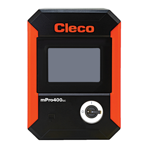
Cleco
Cleco mPro400GCD-S User manual
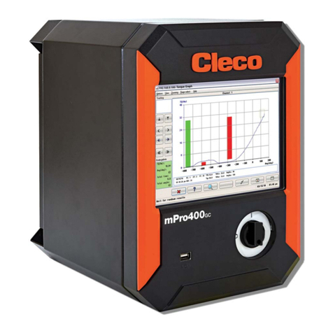
Cleco
Cleco DGD mPro400GC User manual
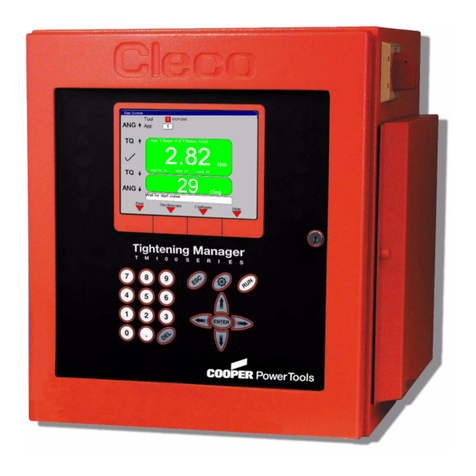
Cleco
Cleco TME-100 Owner's manual
Cleco
Cleco mPro400GCD-P Guide

Cleco
Cleco mPro400GCD-P Guide
Cleco
Cleco DGD mPro400GC User manual

Cleco
Cleco DGD mPro400GC Owner's manual
Cleco
Cleco CellCore 200 Series Guide
Cleco
Cleco DGD mPro400GC Guide

Cleco
Cleco mPro300GCD-STO User manual

