manuals.online logo
Brands
  1. Home
  2. •
  3. Brands
  4. •
  5. Emerson
  6. •
  7. Industrial Electrical
  8. •
  9. Emerson SOLA HD SLCASK-CVR User manual

Emerson SOLA HD SLCASK-CVR User manual

Power Supplies Affected
SLS-05-030-1T, SLS-12-017T, SLS-24-012T
What’s Included
• Part A Cover
• Two Plastic Screws M3x6 mm
• Two Self-tapping Screws M3x6 mm
• Instruction Manual
Assembly Instructions for Cover Installation
Power Supply
Chassis
Self-tapping screws (2 qty)
M3x6 mm Plastic screws (2 qty)
M3x6 mm
*Must use plastic only
Part A Cover
**
FIGURE 1
1. Position the Part A Cover so that it overlaps the exterior surface of the
Power Supply Chassis.
2. Line up the Part A Cover mounting holes with the Power Supply Chassis
mounting holes. Be careful not to pinch the wires.
3. Secure with the provided screws as shown in Figure 1.
Assembly Instructions for OVP
Part A Cover
SLO-12-000-TB
FIGURE 2
1. Locate the mounting holes as shown in Figure 2.
2. Attach SLO-12-000-TB tightly against the inner side of the cover.
3. Position the mounting holes and tighten the screws with 8 kg torque.
4. Assemble the two wires coming out of the SLO-12-000-TB. On the terminal
block, the white wire goes to the “+” and the black wire goes to the “-”.
Notes
1. Be careful while assembling the cover, so that no parts on the PCB are
damaged.
2. When tightening the screws, make sure the torque is 8 kg.
3. Derate power supply by 15% with cover installed.
Linear Power Cover Instruction Manual Model Number: SLCASA-CVR
Part Number: A272-108 Rev 3
September 22, 2008
Buy: www.ValinOnline.com | Phone 844-385-3099 | Email: [email protected]
Power Supplies Affected
SLS-05-060-1T, SLS-12-034T, SLS-24-024T
What’s Included
• Part B Cover
• Two Plastic Screws M3x6 mm
• Two Self-tapping Screws M3x6 mm
• Instruction Manual
Assembly Instructions for Cover Installation
Part B Cover
Self-tapping screws (2 qty)
M3x6 mm
Plastic screws (2 qty)
M3x6 mm
*Must use plastic only
*
*
Power Supply Chassis
FIGURE 1
1. Position the Part B Cover so that it overlaps the exterior surface of the
Power Supply Chassis.
2. Line up the Part B Cover mounting holes with the Power Supply Chassis
mounting holes. Be careful not to pinch the wires.
3. Secure with the provided screws as shown in Figure 1.
Assembly Instructions for OVP
SLO-12-000-TB
Part B Cover
FIGURE 2
1. Locate the mounting holes as shown in Figure 2.
2. Attach SLO-12-000-TB tightly against the inner side of the cover.
3. Position the mounting holes and tighten the screws with 8 kg torque.
4. Assemble the two wires coming out of the SLO-12-000-TB. On the terminal
block, the white wire goes to the “+” and the black wire goes to the “-”.
Notes
1. Be careful while assembling the cover, so that no parts on the PCB are
damaged.
2. When tightening the screws, make sure the torque is 8 kg.
3. Derate power supply by 15% with cover installed.
Linear Power Cover Instruction Manual Model Number: SLCASB-CVR
Part Number: A272-109 Rev 3
September 22, 2008
Buy: www.ValinOnline.com | Phone 844-385-3099 | Email: [email protected]
Power Supplies Affected
SLS-05-090-1T, SLS-12-051T, SLS-15-045T, SLS-24-036T
What’s Included
• Part C Cover
• Six Self-tapping Screws M3x6 mm
• Instruction Manual
Assembly Instructions for Cover Installation
Self-tapping screws (6 qty)
M3x6 mm
FIGURE 1
Part C Cover
Power Supply Chassis
1. Position the Part C Cover so that it overlaps the exterior surface of the
Power Supply Chassis.
2. Line up the Part C Cover mounting holes with the Power Supply Chassis
mounting holes. Be careful not to pinch the wires.
3. Secure with the provided screws as shown in Figure 1.
Assembly Instructions for OVP
SLO-12-000-TB
Part C Cover
FIGURE 2
1. Locate the mounting holes as shown in Figure 2.
2. Attach SLO-12-000-TB tightly against the inner side of the cover.
3. Position the mounting holes and tighten the screws with 8 kg torque.
4. Assemble the two wires coming out of the SLO-12-000-TB. On the terminal
block, the white wire goes to the “+” and the black wire goes to the “-”.
Notes
1. Be careful while assembling the cover, so that no parts on the PCB are
damaged.
2. When tightening the screws, make sure the torque is 8 kg.
3. Derate power supply by 15% with cover installed.
Linear Power Cover Instruction Manual Model Number: SLCASC-CVR
Part Number: A272-110 Rev 2
September 22, 2008
Buy: www.ValinOnline.com | Phone 844-385-3099 | Email: [email protected]
Power Supplies Affected
SLS-05-120-1T, SLS-15-060T, SLD-12-6034-05T, SLD-15-3030-15T,
SLS-12-068T, SLS-24-048T, SLD-12-3434-12T
What’s Included
• Part I Cover
• Four Self-tapping Screws M3x6 mm
• Instruction Manual
Assembly Instructions for Cover Installation
Self-tapping screws (4 qty)
M3x6 mm
Part I Cover
FIGURE 1
Power Supply Chassis
1. Position the Part I Cover so that it overlaps the exterior surface of the Power
Supply Chassis.
2. Line up the Part I Cover mounting holes with the Power Supply Chassis
mounting holes. Be careful not to pinch the wires.
3. Secure with provided screws as shown in Figure 1.
Assembly Instructions for OVP
FIGURE 2
Part I Cover
SLO-12-000-TB
1. Locate the mounting holes as shown in Figure 2.
2. Attach SLO-12-000-TB tightly against the inner side of the cover.
3. Position the mounting holes and tighten the screws with 8 kg torque.
4. Assemble the two wires coming out of the SLO-12-000-TB. On the terminal
block, the white wire goes to the “+” and the black wire goes to the “-”.
Notes
1. Be careful while assembling the cover, so that no parts on the PCB are
damaged.
2. When tightening the screws, make sure the torque is 8 kg.
3. Derate power supply by 15% with cover installed.
Linear Power Cover Instruction Manual Model Number: SLCASI-CVR
Part Number: A272-115 Rev 3
September 22, 2008
Buy: www.ValinOnline.com | Phone 844-385-3099 | Email: [email protected]
Power Supplies Affected
SLS-24-072T
What’s Included
• Part K Cover
• Four Self-tapping Screws M3x6 mm
• Instruction Manual
Assembly Instructions for Cover Installation
Power Supply Chassis
Part K Cover
Self-tapping screws (4 qty)
M3x6 mm
FIGURE 1
1. Position the Part K Cover so that it overlaps the exterior surface of the
Power Supply Chassis.
2. Line up the Part K Cover mounting holes with the Power Supply Chassis
mounting holes. Be careful not to pinch the wires.
3. Secure with the provided screws as shown in Figure 1.
Assembly Instructions for OVP
Part K Cover
FIGURE 2
SLO-12-00-TB
1. Locate the mounting holes as shown in Figure 2.
2. Attach SLO-12-000-TB tightly against the inner side of the cover.
3. Position the mounting holes and tighten the screws with 8 kg torque.
4. Assemble the two wires coming out of the SLO-12-000-TB. On the terminal
block, the white wire goes to the “+” and the black wire goes to the “-”.
Notes
1. Be careful while assembling the cover, so that no parts on the PCB are
damaged.
2. When tightening the screws, make sure the torque is 8 kg.
3. Derate power supply by 15% with cover installed.
Linear Power Cover Instruction Manual Model Number: SLCASK-CVR
Part Number: A272-116 Rev 2
September 22, 2008
Buy: www.ValinOnline.com | Phone 844-385-3099 | Email: [email protected]

Other Emerson Industrial Electrical manuals
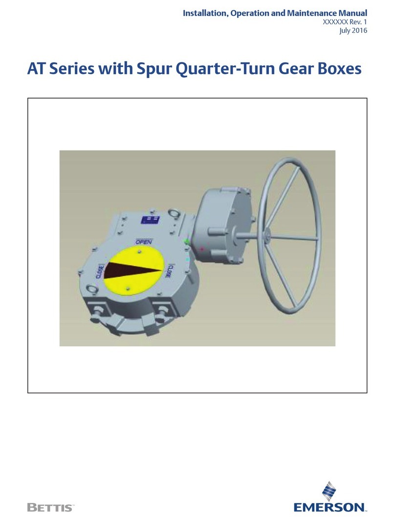
Emerson AT Series User manual

Emerson

Emerson AT Series User manual

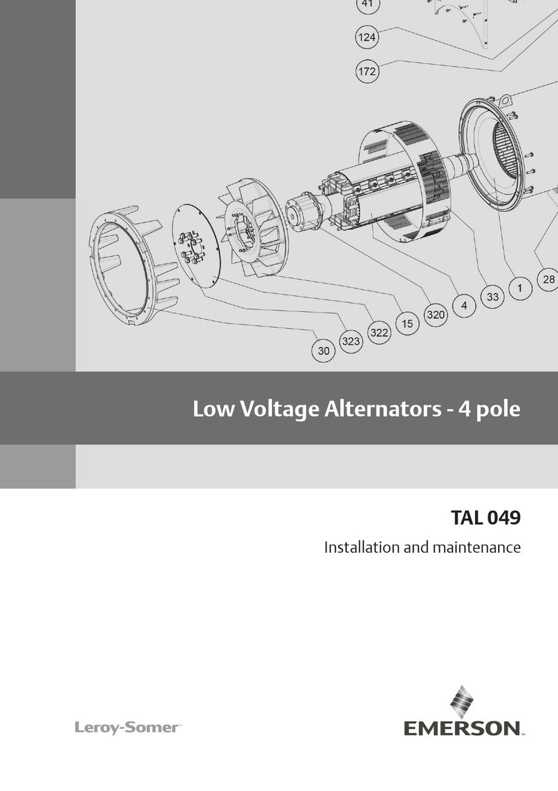
Emerson Leroy-Somer TAL 049 Instruction Manual

Emerson

Emerson Leroy-Somer TAL 049 Instruction Manual

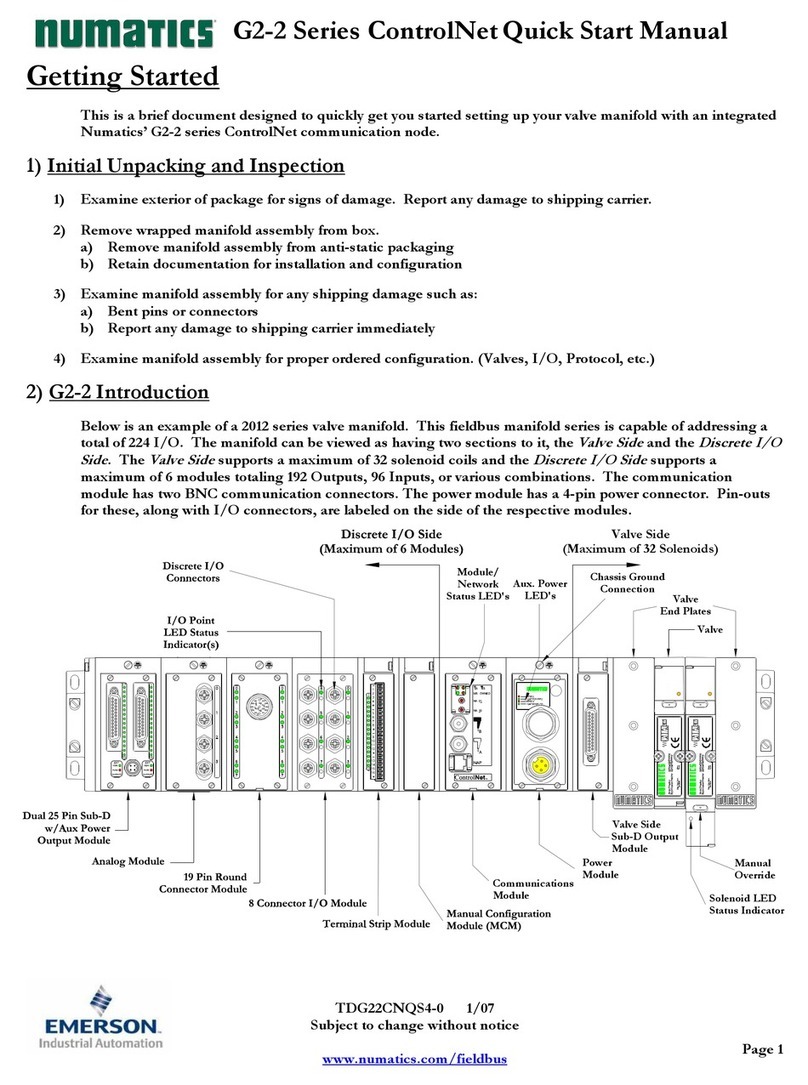
Emerson Numatics G2-2 ControlNet Series Instruction manual
Emerson

Emerson Numatics G2-2 ControlNet Series Instruction manual

Emerson PACSystems RX3i IC695CPE400 User manual

Emerson

Emerson PACSystems RX3i IC695CPE400 User manual

Emerson SolaHD User manual

Emerson

Emerson SolaHD User manual

Emerson AVTRON LOADBANK LPH400 User manual
Emerson

Emerson AVTRON LOADBANK LPH400 User manual

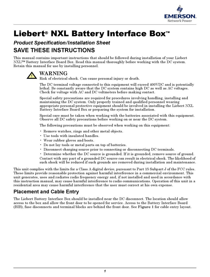
Emerson Liebert NXL User manual

Emerson

Emerson Liebert NXL User manual
Popular Industrial Electrical manuals by other brands

Murata GRM0225C1E9R3BA03 Series Reference sheet

Murata

Murata GRM0225C1E9R3BA03 Series Reference sheet

Schrack LSDD Series operating instructions

Schrack

Schrack LSDD Series operating instructions

Murata GRM1555C1H390JA01 Series Reference sheet

Murata

Murata GRM1555C1H390JA01 Series Reference sheet

AutomationDirect CLICK PLUS C2-03CPU quick start guide

AutomationDirect

AutomationDirect CLICK PLUS C2-03CPU quick start guide

I-Tech IT-E500 Series user manual

I-Tech

I-Tech IT-E500 Series user manual

AutomationDirect DURA PULSE GS-2DBU user manual

AutomationDirect

AutomationDirect DURA PULSE GS-2DBU user manual

red lion VT-IPm2m-***-D Series Installation and maintenance manual

red lion

red lion VT-IPm2m-***-D Series Installation and maintenance manual

Oriental motor SUPER VEXTA U1215GA Operator's manual

Oriental motor

Oriental motor SUPER VEXTA U1215GA Operator's manual

Murata GRM0225C1E5R7DA03 Series Reference sheet

Murata

Murata GRM0225C1E5R7DA03 Series Reference sheet

S&C Scada-Mate SD Installation and operation

S&C

S&C Scada-Mate SD Installation and operation

Schaltbau C295 Series Installation and maintenance instructions

Schaltbau

Schaltbau C295 Series Installation and maintenance instructions

Murata GRM21B5C1H183JA01 Series Reference sheet

Murata

Murata GRM21B5C1H183JA01 Series Reference sheet

Murata GRM31MR72A474KA35 Series Reference sheet

Murata

Murata GRM31MR72A474KA35 Series Reference sheet

Murata GJM0225C1E5R6CB01 Series Reference sheet

Murata

Murata GJM0225C1E5R6CB01 Series Reference sheet

Bredenoord ESaver III Short operation manual

Bredenoord

Bredenoord ESaver III Short operation manual

IKUSI STC 200 user manual

IKUSI

IKUSI STC 200 user manual

Murata GRM1555C1H301JA01 Series Reference sheet

Murata

Murata GRM1555C1H301JA01 Series Reference sheet

Franklin Electric 6" HES Quick installation guide

Franklin Electric

Franklin Electric 6" HES Quick installation guide

manuals.online logo
manuals.online logoBrands
  • About & Mission
  • Contact us
  • Privacy Policy
  • Terms and Conditions

Copyright 2025 Manuals.Online. All Rights Reserved.