manuals.online logo
Brands
  1. Home
  2. •
  3. Brands
  4. •
  5. Emerson
  6. •
  7. Measuring Instrument
  8. •
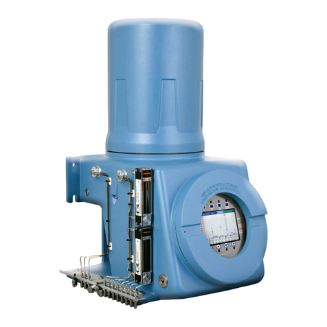
  9. Emerson ROSEMOUNT370XA User manual

Emerson ROSEMOUNT370XA User manual

Other Emerson Measuring Instrument manuals

Emerson CSI 6500 User manual

Emerson

Emerson CSI 6500 User manual

Emerson Rosemount 2051CF series User manual

Emerson

Emerson Rosemount 2051CF series User manual

Emerson Micro Motion SGM Series Quick guide

Emerson

Emerson Micro Motion SGM Series Quick guide

Emerson Daniel 3410 Series Programming manual

Emerson

Emerson Daniel 3410 Series Programming manual

Emerson Rosemount WPG User manual

Emerson

Emerson Rosemount WPG User manual

Emerson FB1100 User manual

Emerson

Emerson FB1100 User manual

Emerson Rosemount 3410 Series User manual

Emerson

Emerson Rosemount 3410 Series User manual

Emerson Micro Motion G-Series User manual

Emerson

Emerson Micro Motion G-Series User manual

Emerson Micro Motion CDM100M A Series Quick guide

Emerson

Emerson Micro Motion CDM100M A Series Quick guide

Emerson Rosemount Analytical FCLi User manual

Emerson

Emerson Rosemount Analytical FCLi User manual

Emerson Daniel 3410 Series Programming manual

Emerson

Emerson Daniel 3410 Series Programming manual

Emerson Dixell XWEB3000 User manual

Emerson

Emerson Dixell XWEB3000 User manual

Emerson Rosemount 2051 Wireless Series User manual

Emerson

Emerson Rosemount 2051 Wireless Series User manual

Emerson Rosemount 3410 Series Programming manual

Emerson

Emerson Rosemount 3410 Series Programming manual

Emerson Rosemount Xi User manual

Emerson

Emerson Rosemount Xi User manual

Emerson Rosemount 485 Annubar User manual

Emerson

Emerson Rosemount 485 Annubar User manual

Emerson LMS1000 User manual

Emerson

Emerson LMS1000 User manual

Emerson Micro Motion TA Series User manual

Emerson

Emerson Micro Motion TA Series User manual

Emerson Rosemount 9295 User manual

Emerson

Emerson Rosemount 9295 User manual

Emerson Rosemount 0085 User manual

Emerson

Emerson Rosemount 0085 User manual

Emerson Rosemount 3051 User manual

Emerson

Emerson Rosemount 3051 User manual

Emerson Fisher 4320 User manual

Emerson

Emerson Fisher 4320 User manual

Emerson A6312 User manual

Emerson

Emerson A6312 User manual

Emerson Penberthy Multiview Manual

Emerson

Emerson Penberthy Multiview Manual

Popular Measuring Instrument manuals by other brands

Powerfix Profi 278296 Operation and safety notes

Powerfix Profi

Powerfix Profi 278296 Operation and safety notes

Test Equipment Depot GVT-427B user manual

Test Equipment Depot

Test Equipment Depot GVT-427B user manual

Fieldpiece ACH Operator's manual

Fieldpiece

Fieldpiece ACH Operator's manual

FLYSURFER VIRON3 user manual

FLYSURFER

FLYSURFER VIRON3 user manual

GMW TG uni 1 operating manual

GMW

GMW TG uni 1 operating manual

Downeaster Wind & Weather Medallion Series instruction manual

Downeaster

Downeaster Wind & Weather Medallion Series instruction manual

Hanna Instruments HI96725C instruction manual

Hanna Instruments

Hanna Instruments HI96725C instruction manual

Nokeval KMR260 quick guide

Nokeval

Nokeval KMR260 quick guide

HOKUYO AUTOMATIC UBG-05LN instruction manual

HOKUYO AUTOMATIC

HOKUYO AUTOMATIC UBG-05LN instruction manual

Fluke 96000 Series Operator's manual

Fluke

Fluke 96000 Series Operator's manual

Test Products International SP565 user manual

Test Products International

Test Products International SP565 user manual

General Sleep Zmachine Insight+ DT-200 Service manual

General Sleep

General Sleep Zmachine Insight+ DT-200 Service manual

Sensa Core Lacto Spark user manual

Sensa Core

Sensa Core Lacto Spark user manual

VOLTCRAFT UTS-1980 operating instructions

VOLTCRAFT

VOLTCRAFT UTS-1980 operating instructions

EBCHQ 94915 Operation manual

EBCHQ

EBCHQ 94915 Operation manual

Balluff BIP LD2-T017-01-EP-S4 Series user guide

Balluff

Balluff BIP LD2-T017-01-EP-S4 Series user guide

Pulsar IMP Lite Series instruction manual

Pulsar

Pulsar IMP Lite Series instruction manual

ETCR 6800 user manual

ETCR

ETCR 6800 user manual

manuals.online logo
manuals.online logoBrands
  • About & Mission
  • Contact us
  • Privacy Policy
  • Terms and Conditions

Copyright 2025 Manuals.Online. All Rights Reserved.

Danalyzer 370XA Gas Chromatograph
Quick Start Guide
1
1
2
3
4
5
6
7
8
9
10
11
12
13
3
2
4
5
6
7 7 8
9
10
11
Typical Installation
370XA Gas Chromatograph
Sample handling system
Pole mount brackets
Atmospheric vent
4-inch Pole
Natural gas pipeline
Carrier gas - Ultra-High Purity (99.9995 %)
Helium (or optional Hydrogen)
Calibration gas
¼ inch stainless steel tubing
Carrier gas switchover valves
⅛inch stainless steel tubing
Heat-traced (insulated) stainless steel tubing
Sample-probe - installed at ⅓rd on center
6
12
13
Minimum Specifications Safety First. Before You Start…
These are the minimum specications recommended for a typical
installation. Please reference the 370XA product manual for more
details or call the factory for additional support.
Standard power:
24V DC (21V DC–30V DC)
50 Watts (start up), 20 Watts (steady state)
Environmental temperature:
-20 °C to 60 °C (-4 °F to 140 °F)
Enclosure protection rating:
IP66 and NEMA 4X
Carrier gas
Must be regulated to 90 PSIG (6.2 BarG)
Zero-grade helium
Zero-grade hydrogen available as an option
Actuation gas
Must be regulated to 90 PSIG (6.2 BarG)
Helium
Nitrogen
Clean dry air
Sample input pressure range:
0.7 to 1.7 BarG (10 to 25 PSIG)
This quick start guide is intended for typical installations only.
For more details, please reference the 370XA product manual or
contact the factory.
WARNING
Use this unit in a well-ventilated area, as required by government
regulations.
WARNING
Exit ports may discharge dangerous levels of toxic vapors; use
proper protection and a suitable exhaust device.
WARNING
Observe and comply with all precautionary signs posted on the
GC. Failure to do so may result in injury or death to personnel or
cause damage to the equipment.
NOTICE
Install and operate all equipment as designed and comply
with all safety requirements. The “Seller” does not accept any
responsibility for installations of the 370XA, or any attached
equipment, in which the installation or operation thereof has
been performed in a manner that is negligent and/or non-
compliant with applicable safety requirements.
NOTICE
The unit is intended to be connected to a 24V DC power source
by qualied personnel in accordance with local and national
codes.
NOTICE
A suitable APPROVED switch and fuse or a circuit breaker shall be
provided to facilitate the disconnection of power.
NOTICE
All gas connections must be properly leak tested at installation.
Step 1- Mounting the 370XA
Recommended Minimum Installation Clearances
1660 mm
(65 in)
50 mm
(2 in)
635 mm
(25 in)
280 mm
(11 in)
665 mm (38 in)
200 mm
(8 in)
460 mm
(18 in)
275.6 mm
(10.849 in)
1 m
(40 in)
200 mm
(8 in)
200 mm
(8 in)
305 mm
(12 in)
705 mm
(28 in)
1000 mm
(40 in)
Attach the 370XA bracket to the pole by sliding the plastic inserts
onto the pole and bolting the two U-bolts through the inserts and
the holes in the bracket. The base of the bracket should be 40 inches
from the ground to make the operator interface easy to use.
1000 mm
(40 in)
9 in
(230 mm)
11 in
(280 mm)
9 in
(230 mm)
11 in
(280 mm)
Secure to the oor with four ½ - inch or ⅜ - inch cement anchors.
The cement foundation should be able to support the weight of the
GC (45 lbs) and its accessories, as well as any other utilities that may
be installed.
If supplying your own pole, it should be four inches in diameter and
at least 55 inches tall.
Mount the bracket on the pole.
1. Install 10 mm or ⅜ in anchors (not supplied) suitable to
anchor the weight of the GC (approx. 20 kg or 45 lbs) as per
the drawing. Use the bracket as a guide to locate the anchors
correctly before drilling the holes. The threads of the anchors
should protrude from the wall by 40 mm (1½ in).
2. Mount the 370XA bracket to the wall anchors and tighten the
nuts. Ensure that the bracket is attached rmly to the wall.
2. Maneuver the GC to insert the two top bolts into the eyelets
of the mounting bracket and allow the bolts to drop down and
hold the GC loosely on the bracket.
12 mm
(.5 in)
Mount the bracket on the wall.
Set the GC onto the bracket.
1. Use a 6 mm hex wrench to screw the top two bolts into the back
of the 370XA without the washers, leaving ½-inch (1.5 cm) of
thread showing.
3. Screw in the two bottom bolts through the mounting bracket
with the washers on. The at washer should be against the
bracket , and the spring washer between the at washer and the
bolt head. Hand tighten these two bolts so that they secure the
GC in place.
4. One at a time, remove the top bolts, put on the washers, and
screw the bolts into the back of the GC and hand tighten.
140 mm
(5½ in)
275 mm
(10⅞in)
1000 mm
(40 in)
40 mm
(1½in)
Step 2 – Sample Handling System and Gas Line Connections
1Mount the single stream sample plate
1. Use the two one-inch bolts and a 5/32 hex wrench to screw the
large mounting bar tightly to the left side of the plate with the
angled foot facing the edge of the plate.
NOTE: To install a multi-stream sample system, please refer to the instructions provided in the sample system installation kit.
2. Use the two half-inch bolts and a 5/32 hex wrench to screw the
small mounting bar loosely to the right side of the plate with
the angled foot facing the edge of the plate.
3. Angle the plate onto the left side of the GC so that the large
mounting block ts behind the left edge of the cut-out. Swing
the right side of the plate around until it attaches to the right
side of the cut-out.
4. Slide the small mounting bar to the right so that it ts behind
the right edge of the cut-out. Tighten the small mounting
block's screws.
2. Connect the atmospheric vents to a vent line of at least ⅜''
diameter that is routed to the atmosphere in a safe area to
ensure there is no back-pressure created on the vents.
NOTE:
The ows out of the vents are:
Sample Vent – 10 to 50 cc/min of sample gas for approximately
3/12 minutes of the 4 minute cycle.
Measure vent –Continuous ow of less than 10 cc/min of carrier
gas and 10 cc of sample gas per analysis cycle.
Sample Bypass – Continuous ow of 150 to 200 cc/min of sample
gas.
2Connect the gas lines
1. Using the tubing supplied with the sample system, connect the
stream, actuation, and calibration gases from the sample plate
to the manifold block (as shown).
3. Open the carrier gas bottle valves and set the regulator to
90 PSIG (6.2 BarG).
4. Open the calibration gas bottle valves and set to
15 PSIG (1 BarG).
5. Open the sample probe valves and set the sample pressure to
20 PSIG (1.4 BarG).
6. Leak check all lines with liquid leak-check solution.
7. Open the sample and calibration valves on the sample panel
and leak-check up to the ttings on the 370XA inlet manifold.
Carrier Gas
Atmospheric
Vent
Bypass
Vent
Sample Gas
Calibration Gas
Calibration
Actuation
Stream 1
Carrier
Stream 1
Sample Vent
Calibration
Measure Vent
Sample Bypass
Atmospheric Vent
Carrier/Actuation
. : 8 ² Ð; Z]_ÐÞ=>¼¦−¦þ
. : 8 ² Ð; Z]_ÐÞ=>¼×# þ
; Zb P] B T]POÐ0_SP]YP_ . : 8 ¦Ð; Z]_ÐÞ=>¼¦−¦þ
. : 8 ¦Ð; Z]_ÐÞ=>¼×# þ
, YLWZRÐ: `_[ `_^Þ¦þ , YLWZRÐ4Y[ `_ / TRT_LWÐ: `_[ `_ / TRT_LWÐ4Y[ `_
(24 VDC)
Step 3 – Wiring
1. Route the power supply lines through the lower left or right cable entry – which ever is the most convenient.
2. Connect power wires to TB8. DO NOT APPLY POWER YET.
3. Route the communication wiring through the lower right cable entry. If additional separation of wiring is required, use the upper right
cable entry for the additional signal wiring.
4. Connect the signal wiring as shown in the diagrams below.
Lower left
cable entry
(24V DC)
Lower right cable entry
Upper right cable entry
Access to terminals
Terminal Board
Terminal Board Map Key
TB8
TB8 TB5
TB4 TB9
TB10 TB2 TB3 TB1
TB9
TB4
TB2
TB3
TB1
TB4
TB5
TB10
RJ45
TB9
Power Wired Ethernet Analog Input Digital Output Digital Input
COM1 Port
(RS-232)
COM1 Port
(RS-232)
COM2 Port
(RS-232)
COM2 Port
(RS-232)
Analog Outputs (2)
Step 4 – Start up
Local Operator Interface
Display Icons Main Menu Display Options
How to Enter Letters from the Keypad
To display a desired letter, repeatedly press the appropriate key until the letter displays. For example, to display the letter “H”, press the 4key
four times.
Turn on the power. The local operator interface (LOI) will show the Emerson logo while the software starts up, and then it will show the
home screen.
FULL COLOR
SCREEN
480 x 272 pixels
UP
EXIT/CANCEL
Alphanumerical
Keypad
OKAY/ACCEPT DOWN
RIGHT
LEFT
ENTER/EDIT
No Alarms
Un-Acknowledged Alarm(s)
Active Alarm(s)
Security Switch Unlocked
Security Switch Locked
View
Hardware
Application
Logs
GC Controls
Tools
As the GC warms up to operating temperature and purges the carrier gas through the
system, congure the GC’s site-specic settings, such as the calibration gas values and
communication settings.
Note: The Login screen will appear if you are not logged in.
Enter your user name and password. The default values for 370XA GCs is:
User: EMERSON
Password: (blank)
Configure the Time and Date
1. From the main menu, select Set GC Time from the Tools menu.
2. Conrm the time and date is correct. To change the time or date, use the arrow keys
to navigate to the eld to change and press the Select/Edit key to edit.
3. Press the key to save the changes, or the key to discard changes and exit to the
main menu.
Configure the Serial Port Settings
1. From the main menu, use the arrow keys to navigate to the Application menu and
select the Communications option.
2. Use the arrow keys to navigate through the various settings and press the Select/Edit
key to edit the appropriate values. The settings must match the settings of the host
device communicating to the 370XA on that port.
3. When all the changes have been made, press the key to save changes and close the
screen.
Configure the Ethernet Port
1. From the main menu, use the arrow keys to navigate to the Application menu and
select the TCP/IP Settings option.
2. Use the arrow keys to navigate through the various settings and press the Select/Edit
key to edit the appropriate values. The settings must match the settings of the host
device communicating to the 370XA on that port.
3. When all the changes have been made, press the Key to save changes and close the
screen.
If required, the Analog Input, Analog Output, Digital Input, and Digital Outputs
settings can be accessed on the Hardware menu. Refer to the manual for further
information
Enter the Calibration Gas Values
1. From the main menu, navigate to the Application menu and select Calibration Gas
Info.
2. Press the Select/Edit edit key and enter the calibration gas concentration values for
each component. Note that the Methane value will be calculated automatically. This
can be used as a check against the value on the certicate to ensure all the values have
been entered correctly.
Step 5 – Configure and Start up the 370XA
Note: If the unit is not in Idle mode, then do the following:
1. Press 3on the keypad to go to the Control menu.
2. Press the down arrow to highlight the Halt command.
3. Press on the keypad and then follow the prompts.
The Home Screen.
The Main Menu, Showing the Set GC Time.
The Set GC Time Screen.
The Communication Screen for the Serial Ports.
The TCP/IP Settings Screen.
The Calibration Concentration Screen.