Emerson Fisher 3710 User manual

www.Fisher.com
Fisher™3710 and 3720 Valve Positioners and
3722 Electro-Pneumatic Converter
Contents
Introduction 2.................................
Scope of Manual 2.............................
Description 2.................................
Positioner to Actuator Mountings List 5.......
Specifications 6...............................
Educational Services 6.........................
Installing the 3722 Converter 6...................
Hazardous Area Classifications and
Special Instructions for “Safe Use” and
Installation in Hazardous Areas
for 3722 Converter 7.......................
CSA 7....................................
FM 8.....................................
ATEX 8...................................
IECEx 10..................................
Installation 11................................
Mounting the Positioner 11......................
Installing the 3710 or 3720
Pneumatic Positioner on Size 25 or 50
585 and 585R Actuators 16..................
Connections 18................................
Supply Connection 19..........................
Output Connections 20........................
Instrument Connection 20......................
Vent Opening, Purge Option, and Actuator
Vent Connection 20.........................
Connecting the Purge Tube 22...............
Electrical Connection for the 3720
Positioner 22...............................
Diagnostic Connections 23.....................
Calibration 25..................................
Setting the Initial Cam Position 25...............
Zero and Span Adjustments 26..................
Standard or Beacon Indicator Alignment 27........
Changing Positioner Action 28....................
Single‐Action/Double‐Action 29.................
Direct‐Action/Reverse‐Action 29.................
Split‐Range Operation 30.......................
Changing the Spool Valve
(To Increase Positioner Output Capacity) 30.....
Changing the Span Adjuster Assembly
(To Change Positioner Input Range) 32.........
Principle of Operation 33........................
Figure 1. Positioners
W6144
W6058‐1
SUPPLY
CONNECTION
3720 POSITIONER MOUNTED
ON 1052 ACTUATOR
3710 POSITIONER MOUNTED
ON 1066 ACTUATOR
Instruction Manual
D101728X012
3710 and 3720 Positioners
September 2017

Instruction Manual
D101728X012
3710 and 3720 Positioners
September 2017
2
Contents (cont'd)
Maintenance 34................................
Positioner Maintenance 34......................
Replacing the Standard or Beacon Indicator 34.
Removing the 3722 Converter 35............
Removing the Positioner 35.................
Removing the Feedback Arm Assembly 36.....
Disassembling the Feedback Arm Assembly
and Span Adjuster Assembly 37............
Removing the Feedback Shaft (Cam Shaft) 37..
Disassembling the Spool Valve, Action Block,
and Gasket 37..........................
Disassembling the Input Module and
Summing Beam Assembly 38.............
Replacing the Input Module Diaphragm 39.....
Assembling the Input Module and Summing
Beam Assembly 40......................
Assembling the Spool Valve, Action Block,
and Gasket 41..........................
Assembling the Feedback Shaft
(Cam Shaft) 42..........................
Replacing the Feedback Arm Assembly
and Span Adjuster Assembly 42............
3722 Converter Maintenance 42.................
Replacing the Converter Primary O‐Ring
and Filter 42............................
Disassembling the 3722 Converter 43.........
Assembling the 3722 Converter 43...........
Testing the 3722 Converter Module 44........
Parts Ordering 44...............................
Parts Kits 44...................................
Parts List 44...................................
Positioner Common Parts 45.....................
Diagnostic Connections 48.......................
3722 Electro‐Pneumatic Converter 49.............
Positioner Mounting Parts 50.....................
Mounting Parts for Mounting Positioner
on 585 and 585R Actuators 53..................
Fittings 53.....................................
Loop Schematics 53.............................
Introduction
Scope of Manual
This instruction manual includes installation, operation, calibration, maintenance, and parts ordering information for
the Fisher 3710 pneumatic positioner and 3720 electro‐pneumatic positioner.
This manual also provides field installation and maintenance information for the Fisher 3722 electro‐pneumatic
converter. Refer to separate instruction manuals for information on the actuator, control valve, and other accessories.
Do not install, operate, or maintain a 3710 pneumatic positioner, a 3720 electro‐pneumatic positioner or a 3722
electro‐pneumatic converter without being fully trained and qualified in valve, actuator and accessory installation,
operation and maintenance. To avoid personal injury or property damage it is important to carefully read, understand,
and follow all of the contents of this manual, including all safety cautions and warnings. If you have any questions
about these instructions, contact your Emerson sales office or Local Business Partner before proceeding.
Description
The 3710 pneumatic positioner and 3720 electro‐pneumatic positioner are used with either diaphragm actuators
(spring return) or piston rotary actuators (spring return or double‐action) as shown in figure 1. These positioners
provide a valve ball or disk position for a specific input signal. These positioners can easily be configured to provide
single‐ or double‐action output for rotary actuators.
The 3710 pneumatic positioner accepts a pneumatic input signal. The 3720 electro‐pneumatic positioner accepts a
milliampere (mA), direct current (DC), input signal. Refer to table 1 for an explanation of type numbers.
The 3710 pneumatic positioner provides a valve position for a standard pneumatic input signal. The positioner may
also be split‐ranged. See table 3 for input signal ranges.
The 3720 electro‐pneumatic positioner provides a valve position for a milliampere (mA), direct current (DC), input
signal. The positioner may also be split‐ranged. See table 3.

Instruction Manual
D101728X012
3710 and 3720 Positioners
September 2017
3
Table 1. Specifications
Available Configurations
3710: JSingle‐ or Jdouble‐acting pneumatic
rotary valve positioner
3720: JSingle‐ or Jdouble‐acting
electro‐pneumatic rotary valve positioner
consisting of a 3710 with a 3722 attached
3722: An electro‐pneumatic converter that
converts a 4-20 mA DC input signal to a 0.2 to
1.0 bar (3 to 15 psig) signal for the pneumatic
positioner
Input Signal
3710:
Standard: J0.2 to 1.0 bar (3 to 15 psig)or J0.4 to
2.0 bar (6 to 30 psig)
Split‐Range: J0.2 to 0.6 bar (3 to 9 psig) and 0.6 to
1.0 bar (9 to 15 psig) or J0.4 to 1.2 bar (6 to 18
psig) and 1.2 to 2.0 bar (18 to 30 psig)
3720:
Standard: J4-20 mA DC constant current with
30 VDC maximum compliance voltage
Split‐Range: J4-12 mA DC or 12-20 mA DC
Equivalent Circuit
3720: 120 ohms shunted by three 5.6 V zener
diodes. See figure 15.
Output Signal
Pneumatic pressure as required by the actuator up
to full supply pressure
Action(1):Field‐reversible between Jdirect and
Jreverse within the pneumatic positioner
Supply Pressure(2)
Recommended: 0.3 bar (5 psig) above actuator
requirement
Maximum: 10.3 bar (150 psig) or maximum
pressure rating of the actuator, whichever is lower
Supply Medium
3710: Air or Natural Gas
3720: Air
Supply medium must be clean, dry, and noncorrosive
Per ISA Standard 7.0.01
A maximum 40 micrometer particle size in the air
system is acceptable. Further filtration down to 5
micrometer particle size is recommended. Lubricant
content is not to exceed 1 ppm weight (w/w) or
volume (v/v) basis. Condensation in the air supply
should be minimized
Per ISO 8573-1
Maximum particle density size: Class 7
Oil content: Class 3
Pressure Dew Point: Class 3 or at least 10_C less than
the lowest ambient temperature expected
3720 positioners are not approved for use with
natural gas as the supply medium
Steady‐State Air Consumption(3)
3710:
6 mm Standard Spool Valve: 0.82 normal m3/hr
(29 scfh) at 4.1 bar (60 psig) supply pressure
3720:
6 mm Spool Valve: 1.0 normal m3/hr (36 scfh) at
4.1 bar (60 psig) supply pressure
Maximum Supply Air Demand(3)
(Double Acting Output)
6 mm Spool Valve: 20 normal m3/hr (700 scfh) at
4.1 bar (60 psig) supply pressure
Typical Performance(4)
3710:
Independent Linearity: ±0.5% of output span
Hysteresis: 0.5% of output span
Deadband: 0.3% of input span
3720:
Independent Linearity: ±1.0% of output span
Hysteresis: 0.6% of output span
Deadband: 0.35% of input span
Electromagnetic Compatibility for 3722
Meets EN 61326‐1:2013
Immunity—Industrial locations per Table 2 of
the EN 61326‐1 standard. Performance is
shown in table 2 below.
Emissions—Class A
ISM equipment rating: Group 1, Class A
Note: Electromagnetic Interference (EMI)
specifications also apply to 3720 positioners
Operating Influences
Supply Pressure Sensitivity: A 10% change in supply
pressure changes the valve shaft position less than
the following percentages of valve rotation:
3710: 1.0% at 4.1 bar (60 psig) supply pressure
3720: 1.5% at 4.1 bar (60 psig) supply pressure
Operative Temperature Limits(2)
J-40 to 80_C (-40 to 180_F), J-50 to 107_C
(-58 to 225_F)
‐ continued ‐

Instruction Manual
D101728X012
3710 and 3720 Positioners
September 2017
4
Table 1. Specifications (Continued)
Hazardous Area Classification for 3710 Positioner
3710 pneumatic positioners comply with the
requirements of ATEX Group II Category 2 Gas and
Dust
Electrical Classifications for 3722 Converter
CSA— Intrinsically Safe, Explosion-proof, Type n,
Dust Ignition-proof
FM— Intrinsically Safe, Explosion-proof, Type n,
Dust Ignition-proof, Non‐incendive
ATEX— Intrinsically Safe, Flameproof, Type n
IECEx— Intrinsically Safe, Flameproof, Type n
Note: These classifications also apply to the 3720
positioner
Refer to Hazardous Area Classifications and Special
Instructions for “Safe Use” and Installation in
Hazardous Locations, starting on page 7, for
additional information.
Housing Classification for 3722 Converter
CSA— Type 3 Encl. ATEX— IP64
FM— NEMA 3, IP54 IECEx— IP54
Mount instrument with vent on side or bottom if
weatherproofing is a concern.
Note: These classifications also apply to the 3720
positioner
Other Classifications/Certifications for 3722
Converter
CUTR—Customs Union Technical Regulations (Russia,
Kazakhstan, Belarus, and Armenia)
INMETRO— National Institute of Metrology, Quality
and Technology (Brazil)
KGS— Korea Gas Safety Corporation (South Korea)
Contact your Emerson sales office or Local Business
Partner for classification/certification specific
information
Pressure Connections
1/4 NPT internal
Electrical Connection for 3720 Positioner
1/2‐14 NPT conduit connection
Rotary Valve Rotation
J90 degrees (standard) J60 degrees (optional)
Approximate Weight
3710: 2.04 kg (4.5 pounds)
3720: 2.72 kg (6.0 pounds)
Declaration of SEP
Fisher Controls International LLC declares this
product to be in compliance with Article 4
paragraph 3 of the PED Directive 2014/68/EU. It was
designed and manufactured in accordance with
Sound Engineering Practice (SEP) and cannot bear
the CE marking related to PED compliance.
However, the product may bear the CE marking to
indicate compliance with other applicable European
Community Directives.
NOTE: Specialized instrument terms are defined in ANSI/ISA Standard 51.1 ‐ Process Instrument Terminology.
1. For direct action, an increasing input signal extends actuator rod. For reverse action, an increasing input signal retracts actuator rod.
2. The pressure and temperature limits in this document, and any applicable code or standard limitation should not be exceeded.
3. Normal cubic meters per hour (0°C and 1.01325 bar absolute). Scfh — standard cubic feet per hour (60°F and 14.7 psia).
4. Typical values tested using a 1061 size 30 actuator at 4.1 bar (60 psig) supply pressure. Performance may vary with other actuator types and supply pressures.
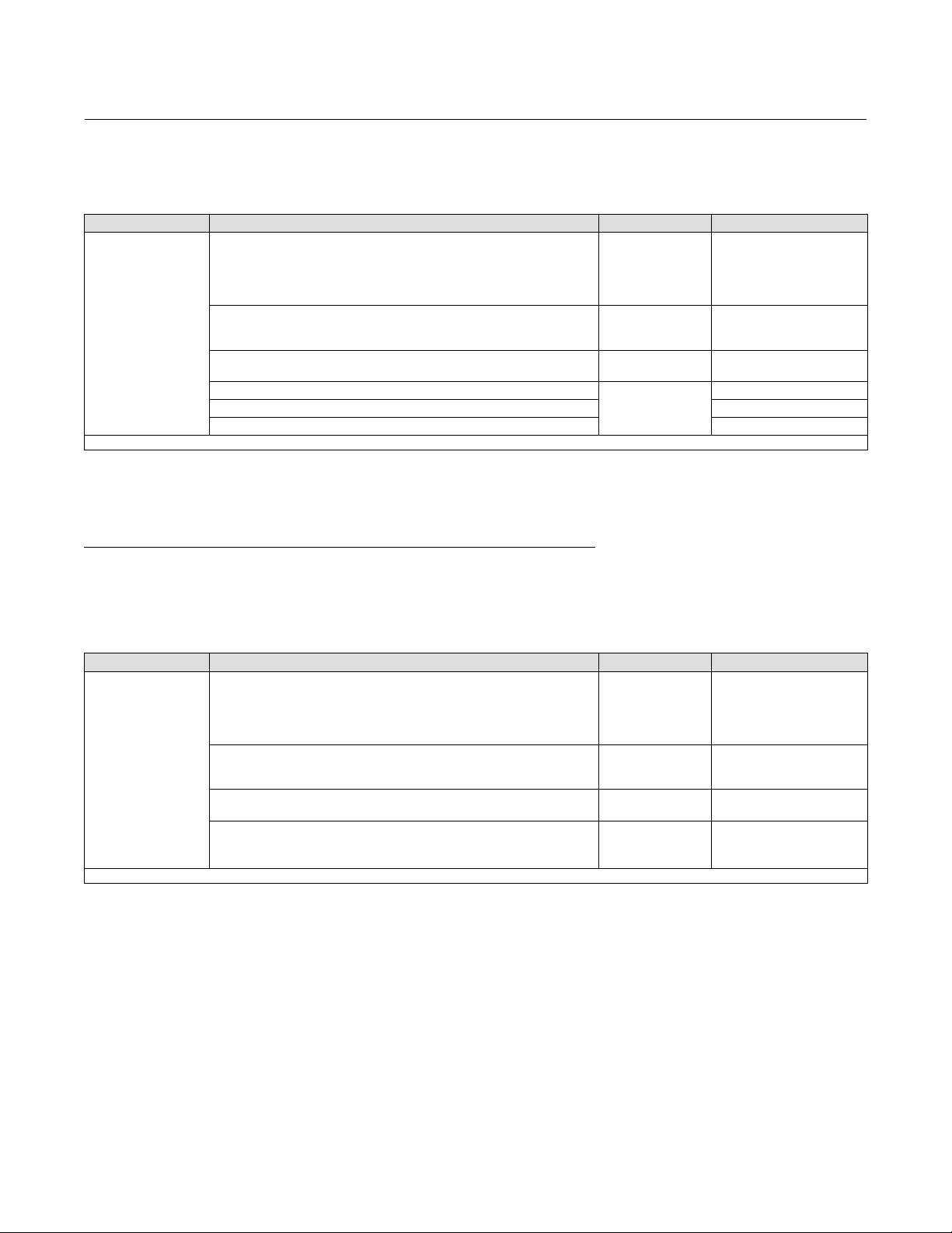
Table 2. Fisher 3722 Electro‐Converter(1) EMC Summary Results—Immunity
Port Phenomenon Basic Standard Test Level Performance
Criteria(2)
Enclosure
Electrostatic Discharge (ESD) IEC 61000‐4‐2 4 kV contact
8 kV air A
Radiated EM field IEC 61000‐4‐3
80 to 1000 MHz @ 10V/m with 1 kHz AM at 80%
14000 to 2000 MHz @ 3V/m with 1 kHz AM at 80%
2000 to 2700 MHz @ 1V/m with 1 kHz AM at 80%
A
Rated power frequency magnetic
field IEC 61000‐4‐8 60 A/m at 50 Hz A
I/O signal/control
Burst (fast transients) IEC 61000‐4‐4 1 kV A
Surge IEC 61000‐4‐5 1 kV (line to ground only, each) B
Conducted RF IEC 61000‐4‐6 150 kHz to 80 MHz at 3 Vrms A
Specification limit = ±1% of span
1. The information contained in this table also applies to the 3720 positioner.
2. A = No degradation during testing. B = Temporary degradation during testing, but is self‐recovering.

Instruction Manual
D101728X012
3710 and 3720 Positioners
September 2017
5
Table 3. Input Signal Range
POSITIONER INPUT SIGNAL RANGE
Pneumatic Electronic
3710
w/3 to 15 psig span adj. ass'y
(no color coding)
J0.2 to 1.0 bar (3 to 15 psig)
J0.2 to 0.6 bar (3 to 9 psig) and
0.6 to 1.0 bar (9 to 15 psig), split‐ranging
–––
3710
w/6 to 30 psig span adj. ass'y
(red color coding)
J0.4 to 2.0 bar (6 to 30 psig)
J0.4 to 1.2 bar (6 to 18 psig) and
1.2 to 2.0 bar (18 to 30 psig), split‐ranging
–––
3720 ––– J4-20 mA DC
J4-12 mA DC or 12-20 mA DC, split‐ranging
Positioner to Actuator Mountings List
The positioner mounts directly to the actuator cover plate of Fisher 1051, 1052, and 1061 actuators. See table 4 for
actuator sizes.
Figure 2 shows a positioner ready for mounting on a piston rotary actuator. A mounting plate (key 43) is used to
mount the positioner base plate to Fisher 1051, 1052, 1061, 1066, and 2052 actuators. See table 4 for actuator sizes.
The positioner also mounts on a Fisher 585 and 585R size 25 or 50 sliding‐stem actuator. A mounting plate (key 43) is
used to mount the positioner base plate to the actuator.
W6059‐1
MOUNTING
SCREW
FEEDBACK
SHAFT
MOUNTING SCREWS TIE BAR
EXTENSION (KEY 44)
POSITIONER
MOUNTING
PLATE (KEY 43)
Figure 2. Mounting the Positioner Base Plate

Instruction Manual
D101728X012
3710 and 3720 Positioners
September 2017
6
Table 4. Positioner to Actuator Mountings
POSITIONER TO ACTUATOR MOUNTINGS
Direct Mounting to Actuator Cover Plate(1) Mounting Plate Required
S1051, size 30(2), 40, and 60
S1052, sizes 30(2), 40, 60, and 70
S1061, size 30, 40, 60, and 68
S1051, size 33
S1052, size 20, 33
S1061, size 80, 100
S1066, size 20, 27, and 75
S2052, size 1, 2, and 3
SNAMUR Mounting
1. Includes purge tube option.
2. The size 30 actuator is no longer manufactured by Emerson. 3710 and 3720 positioners are available for field installation on existing size 30 actuators.
Specifications
Specifications are shown in table 1.
Educational Services
For information on available courses for 3710 pneumatic positioners or 3720 electro‐pneumatics positioners, as well
as a variety of other products, contact:
Emerson Automation Solutions
Educational Services, Registration
Phone: +1-641-754-3771 or +1-800-338-8158
e‐mail: [email protected]
emerson.com/fishervalvetraining
Installing the 3722 Converter
See figure 3.
WARNING
Avoid personal injury from sudden release of process pressure. Before mounting the 3720 electro‐pneumatic positioner or
3722 electro‐pneumatic converter:
D Wear protective eyewear, gloves and clothing whenever possible.
D Do not remove the actuator from the valve while the valve is still pressurized.
D Disconnect any operating lines providing air pressure, electric power, or a control signal to the actuator. Be sure the
actuator cannot suddenly open or close the valve.
D Use bypass valves or completely shut off the process to isolate the valve from process pressure. Relieve process pressure
on both sides of the valve.
D Relieve any supply or output pressure in the existing positioner.
D When installing an electro‐pneumatic positioner or converter in a hazardous area, turn off control signals until
installation is complete. Be sure all safety barriers, connections, and the converter housing cap and O‐ring are properly
installed before supply a control signal to the unit.

Instruction Manual
D101728X012
3710 and 3720 Positioners
September 2017
7
D Use lock‐out procedures to be sure that the above measures stay in effect while you work on the equipment.
D Do not open where an explosive dust atmosphere is present.
D Check with your process or safety engineer for any additional measures that must be taken to protect against process
media.
WARNING
The positioner can provide full supply pressure to any connected equipment. To avoid personal injury and equipment
damage, make sure supply pressure never exceeds the maximum safe working pressure of any connected equipment.
CAUTION
Do not use sealing tape on pneumatic connections. This instrument contains small passages that may become obstructed
by detached sealing tape. Thread sealant paste should be used to seal and lubricate pneumatic threaded connections.
Hazardous Area Classifications and Special Instructions for “Safe Use” and
Installation in Hazardous Locations for 3722 Converter
Note
These Special Instruction for “Safe Use” and Installation in Hazardous Location also apply to 3720 positioners.
Certain nameplates may carry more than one approval, and each approval may have unique installation/wiring
requirements and/or conditions of “safe use”. These special instructions for “safe use” are in addition to, and may
override, the standard installation procedures. Special instructions are listed by approval.
Note
This information supplements the nameplate markings affixed to the product.
Always refer to the nameplate itself to identify the appropriate certification. Contact your Emerson sales office or Local Business
Partner for approval/certification information not listed here.
WARNING
Failure to follow these conditions of “safe use” could result in personal injury or property damage from fire or explosion,
and area re‐classification.
CSA
Intrinsically Safe, Explosion-proof, Type n, Dust Ignition-proof
No special conditions for safe use.

Instruction Manual
D101728X012
3710 and 3720 Positioners
September 2017
8
Refer to table 5 for approval information.
Table 5. Hazardous Area Classifications for Fisher 3722 Converter(1)—CSA (Canada)
Certification Body Certification Obtained Entity Rating Temperature Code
CSA
Intrinsically Safe
Ex ia IIC T4/T5/T6 per drawing GE28591 (figure 34)
Ex ia Intrinsically Safe
Class I, II Division 1 GP A,B,C,D,E,F,G T4/T5/T6
per drawing GE28591 (figure 34)
Vmax = 30 VDC
Imax = 150 mA
Pi = 1.25 W
Ci = 0 nF
Li = 0 mH
T4 (Tamb ≤ 82°C)
T5 (Tamb ≤ 62°C)
T6 (Tamb ≤ 47°C)
Explosion-proof
Ex d IIC T5
Class I, Division 1, GP A,B,C,D T5
- - - T5 (Tamb ≤ 82°C)
Type n
Ex nA IIC T6 - - - T6 (Tamb ≤ 82°C)
Class I, Division 2, GP A,B,C,D T6
- - -
T6 (Tamb ≤ 82°C)
Class II, Division 1, GP E,F,G T5 T5 (Tamb ≤ 82°C)
Class II, Division 2, GP F,G T6 T6 (Tamb ≤ 82°C)
1. These hazardous area classification also apply to 3720 positioners.
FM
Intrinsically Safe, Explosion-proof, Type n, Dust Ignition-proof, Non‐incendive
No special conditions for safe use.
Refer to table 6 for approval information.
Table 6. Hazardous Area Classifications for Fisher 3722 Converter(1)—FM (United States)
Certification Body Certification Obtained Entity Rating Temperature Code
FM
Intrinsically Safe
Class I Zone 0 AEx ia IIC T4/T5/T6 per drawing GE28590 (figure 35)
Class I, II, III Division 1 GP A,B,C,D,E,F,G T4/T5/T6
per drawing GE28590 (figure 35)
Vmax = 30 VDC
Imax = 150 mA
Pi = 1.25 W
Ci = 0 nF
Li = 0 mH
T4 (Tamb ≤ 82°C)
T5 (Tamb ≤ 62°C)
T6 (Tamb ≤ 47°C)
Explosion-proof
Class I Zone 1 AEx d IIC T5
Class I, Division I, GP A,B,C,D T5
- - - T5 (Tamb ≤ 82°C)
Type n
Class I Zone 2 AEx nA IIC T5 - - - T5 (Tamb ≤ 82°C)
Class I, Division 2, GP A,B,C,D T5
Class II, Division 1, GP E,F,G T5
Class II, Division 2, GP F,G T5
- - - T5 (Tamb ≤ 82°C)
1. These hazardous area classification also apply to 3720 positioners.
ATEX
Standards Used for Certification
EN 60079-0: 2012 EN 60079-31: 2009
EN 60079-1: 2007 EN 61241-0: 2006
EN 60079-11: 2012 EN 61241-1: 2004
EN 60079-15: 2010 EN 61241-11: 2006

Instruction Manual
D101728X012
3710 and 3720 Positioners
September 2017
9
Special Conditions for Safe Use
Intrinsically Safe
This equipment is intrinsically safe and can be used in potentially explosive atmospheres.
The electrical parameters of certified equipment which can be connected to the device must not exceed one of these
following values: U0≤ 30 VDC; I0≤ 150 mA; P0≤ 1.25 W
Ambient temperature: T6, at Tamb = 47_C ; T5, at Tamb = 62_C ; T4, at Tamb = 82_C
Flameproof
The flame path is other than required by EN 60079‐1. Contact the manufacturer for information on the dimensions of
the flameproof joints.
Electrical connections are typically made using either cable or conduit.
D If using a cable connection, the cable entry device shall be certified in type of explosion protection flameproof
enclosure “d”, suitable for the conditions of use and correctly installed.
For ambient temperatures over 70_C, cables and cable glands suitable for at least 90_C shall be used.
D If using a rigid conduit connection, an Ex d certified sealing device such as a conduit seal with setting compound
shall be provided immediately to the entrance of the enclosure.
For ambient temperatures over 70_C, the wiring and setting compound in the conduit seal shall be suitable for at least
90_C.
Type n
No special conditions for safe use.
Refer to table 7 for approval information.
Table 7. Hazardous Area Classifications for Fisher 3722 Converter(1)—ATEX
Certification Certification Obtained Entity Rating Temperature Code
ATEX
II 1 G & D
Intrinsically Safe
Gas
Ex ia IIC T4/T5/T6 Ga
Ui = 30 VDC
Ii = 150 mA
Pi = 1.25 W
Ci = 0 nF
Li = 0 mH
T4 (Tamb ≤ 82°C)
T5 (Tamb ≤ 62°C)
T6 (Tamb ≤ 47°C)
Dust
Ex ia IIIC Da T120 °C (Tamb ≤ 82°C)/T100 °C
(Tamb ≤ 62°C) / T85 °C (Tamb ≤ 47°C)
- - -
II 2 G & D
Flameproof
Gas
Ex d IIC T5 Gb - - -
T5 (Tamb ≤ 82°C)
Dust
Ex tb IIIC T82 °C Db (Tamb ≤ 79°C) - - -
II 3 G & D
Type n
Gas
Ex nA IIC T6 Gc - - -
T6 (Tamb ≤ 82°C)
Dust
Ex tc IIIC Dc T85 °C (Tamb ≤ 82°C) - - -
1. These hazardous area classification also apply to 3720 positioners.

Instruction Manual
D101728X012
3710 and 3720 Positioners
September 2017
10
IECEx
Conditions of Certification
Intrinsically Safe
WARNING
Substitution of components may impair intrinsic safety.
-40_C ≤ Ta ≤ +82_C; T6 (Ta ≤ +47_C); T5 (Ta ≤ +62_C); T4 (Ta ≤ +82_C)
Entity Parameters: Ui =30 V, li = 150 mA, Pi = 1.25 W, Ci = 0 nF, Li = 0 mH
Flameproof
WARNING
Disconnect power before opening.
-40_C ≤ Ta ≤ +82_C; T5 (Ta ≤ +82_C)
Type n
WARNING
Disconnect power before opening.
-40_C ≤ Ta ≤ +82_C; T6 (Ta ≤ +82_C)
Refer to table 8 for approval information.
Table 8. Hazardous Area Classifications for Fisher 3722 Converter(1)—IECEx
Certification Certification Obtained Entity Rating Temperature Code
IECEx
Intrinsically Safe
Gas
Ex ia IIC T4/T5/T6 Ga
Ui = 30 VDC
Ii = 150 mA
Pi = 1.25 W
Ci = 0 nF
Li = 0 mH
T4 (Tamb ≤ 82°C)
T5 (Tamb ≤ 62°C)
T6 (Tamb ≤ 47°C)
Flameproof
Gas
Ex d IIC T5 Gb
- - - T5 (Tamb ≤ 82°C)
Type n
Gas
Ex nA IIC T6 Gc
- - - T6 (Tamb ≤ 82°C)
1. These hazardous area classification also apply to 3720 positioners.

Instruction Manual
D101728X012
3710 and 3720 Positioners
September 2017
11
Installation
To change an existing 3710 positioner into a 3720 positioner, install a 3722 electro‐pneumatic converter (figure 3).
The 3722 electro‐pneumatic converter mounts over the input and supply connections of the 3710 positioner.
Figure 3. Fisher 3722 Electro‐Pneumatic Converter
W6145
EXTERNAL GROUNDING
SCREW
SUPPLY CONNECTION
1/2‐NPT CONDUIT CONNECTION
1. Be sure all safety procedures have been followed. Remove the input and supply connections from the existing 3710
base plate and clean the ports.
2. Locate the two O‐rings (key 85, figure 32) and properly lubricate (key 82) them. Place one O‐ring in the recessed
area surrounding the input port on the positioner base plate. Place the other O‐ring around the supply port.
3. Locate the two socket head mounting screws (key 84). Properly orient the converter and secure it to the positioner
base plate with the mounting screws. Be sure the O‐rings remain in place while securing the converter to the
positioner base plate.
4. Connect supply pressure to the converter supply port.
Mounting the Positioner
Typically, a positioner is ordered with an actuator. At the factory, the positioner is mounted on the actuator and
calibrated. However, a positioner can be ordered separately and mounted on an existing actuator.
To field‐mount a positioner to an existing actuator, an actuator cover plate with mounting holes and purge tube
knockout may be required. Check the existing actuator cover plate. It must have three positioner mounting holes and,
for specific actuators, a purge tube knockout. See table 4.

Instruction Manual
D101728X012
3710 and 3720 Positioners
September 2017
12
If the proper mounting holes are present, perform the following mounting procedure and then follow the calibration
procedures in this instruction manual. Refer to the appropriate instruction manuals for actuator and valve mounting
procedures.
WARNING
Avoid personal injury from sudden release of process pressure. Before mounting the 3720 electro‐pneumatic positioner or
3722 electro‐pneumatic converter:
D Wear protective eyewear, gloves and clothing whenever possible.
D Do not remove the actuator from the valve while the valve is still pressurized.
D Disconnect any operating lines providing air pressure, electric power, or a control signal to the actuator. Be sure the
actuator cannot suddenly open or close the valve.
D Use bypass valves or completely shut off the process to isolate the valve from process pressure. Relieve process pressure
on both sides of the valve.
D Vent the power actuator loading pressure and relieve any actuator spring precompression.
D Use lock‐out procedures to be sure that the above measures stay in effect while you work on the equipment.
D When installing a positioner or converter in a hazardous area, turn off control signals until installation is complete. Be
sure all safety barriers, connections, and the converter housing cap and O‐ring are properly installed before supplying a
control signal to the unit.
D Check with your process or safety engineer for any additional measures that must be taken to protect against process
media.
WARNING
The positioner can provide full supply pressure to any connected equipment. To avoid personal injury and equipment
damage, make sure supply pressure never exceeds the maximum safe working pressure of any connected equipment.
Note
The positioner mounts directly to the actuator cover plate of several Fisher actuators. See table 4. To directly mount the positioner
to an existing Fisher actuator, you must use an actuator cover plate with three positioner mounting holes and the 5/8‐inch purge
option knockout plug.
See the parts list for the specific actuator cover plate required above to integrally mount the positioner.
See figures 4 and 33 for positioner mounting drawings.
Note
To mount the positioner to an actuator with an existing Fisher 3610 positioner, remove the 3610 positioner and replace it with an
appropriate metal cover plate and four cap screws. For assistance, contact your Emerson sales office or Local Business Partner.

Instruction Manual
D101728X012
3710 and 3720 Positioners
September 2017
13
Figure 4. Typical Positioner/Actuator Combinations
42B8466‐A
42B8466‐A
3710 POSITIONER MOUNTED ON A
1061 SIZE 30 ACTUATOR
3720 POSITIONER MOUNTED ON A
1061 SIZE 30 ACTUATOR
NOTES:
FIGURE 33 SHOWS ADDITIONAL POSITIONER/ACTUATOR COMBINATIONS
ACTUATOR COVER PLATE REQUIRED WHEN REPLACING AN INSTALLED 3610 POSITIONER
1

Instruction Manual
D101728X012
3710 and 3720 Positioners
September 2017
14
1. See figure 5 for a typical actuator. Remove the actuator travel indicator machine screws, travel indicator, and
actuator cover cap screws.
Note
When removing the actuator cover plate, take care not to change the position of the rod end bearing on the end of the turnbuckle
inside the actuator housing.
2. If necessary, install a new cover plate.
a. Remove the existing cap screws and actuator cover plate from the actuator housing.
b. Remove the retaining ring (e‐clip) and hub from the cover plate.
c. Install the hub and retaining ring into the new actuator/positioner cover plate.
Note
Position the actuator cover plate so the positioner mounting holes on the new cover plate allow placement of the positioner in the
desired orientation.
Actuator cover alignment on the 1052 actuator can be aided by moving the actuator slightly away from its “up” travel stop using a
regulated air source. If the hole alignment cannot be obtained in this manner, temporarily loosen the cap screws that secure the
housing to the mounting yoke and shift the housing slightly. Do not completely travel the actuator while the cover is removed.
Tighten the actuator cap screws before continuing.
3. Position the new actuator/positioner cover plate so the positioner mounting holes on the new cover plate allow
placement of the new positioner in the desired orientation. Secure the new cover plate to the actuator.
4. Install the positioner tie bar (key 42) in place of the travel indicator on the actuator hub.
Note
Before installation of the positioner mounting plate (key 43), review the mounting drawings (figures 4 and 33). Properly align the
positioner mounting plate before attaching the mounting plate to the actuator cover plate. Note that the three positioner
mounting holes must be aligned to match the three mounting screws which will pass through the base of the positioner.
5. If the specific actuator requires a positioner mounting plate (key 43), install the mounting plate using the cap
screws (key 45).
6. Unscrew the four captive cover screws and remove the cover assembly (key 7) from the positioner.
7. See figure 6. Loosen the cam locknut (key 37) and rotate the feedback shaft (key 38) as necessary to align the slot in
the feedback shaft end with the tie bar on the actuator hub. Tighten the cam locknut.
8. Align the positioner with the mounting holes in the new actuator cover plate or positioner mounting plate. Be sure
that the tie bar fits securely into the feedback shaft end slot. Secure the positioner to the actuator cover plate or
mounting plate using the (hex) socket head cap screws (key 46).
9. Before installing the positioner cover, properly align the valve position indicator (standard, low‐profile indicator or
optional beacon indicator). Follow the standard or beacon indicator alignment procedure given in this instruction
manual. Then, install the positioner cover assembly.

Instruction Manual
D101728X012
3710 and 3720 Positioners
September 2017
15
Figure 5. Typical Piston Actuator (Fisher 1061)
W6147‐1
W6146‐1
REAR VIEW, POSITIONER BASE PLATE, AND MOUNTING AREA
TIE BAR, MOUNTING PLATE REMOVED
Figure 6. Loosening the Cam Locknut
W5916

Instruction Manual
D101728X012
3710 and 3720 Positioners
September 2017
16
Installing the 3710 or 3720 Pneumatic Positioner on Size 25 or 50 585 and
585R Actuators
Refer to figures 7, 8, and 9 for key number locations unless noted otherwise.
Figure 7. Typical Fisher 3710 Positioner Mounted on a 585 Actuator
CAP SCREW
(KEY 99)
LOCK WASHER
(KEY 100)
HEX NUT
(KEY 96)
SPACER
(KEY 61)
MOUNTING PLATE
(KEY 43)
DRIVE STUD BRACKET
(KEY 98)
CAP SCREW
(KEY 93)
MOUNTING BEARING
(KEY 97)
CAP SCREW
(KEY 46)
CAP SCREW
KEY 45
LOCK
WASHER
(KEY 92)
1. An actuator stem bracket is supplied with the positioner. Assemble the various positioner feedback parts to the
stem bracket as follows:
a. Refer to figure 8. Install the roller bearing (key 101) on the drive stud (key 95) and secure with the E‐ring
(key 102).
b. Refer to figure 9. Attach the drive stud (with roller bearing) to the drive stud bracket (key 98) with 1/4‐inch hex
nut (key 96), lock washer (key 100), and flat washer (key 103). Place the flat washer between the lock washer and
the hex nut. The washers and hex nut should all be on the same side of the drive stud bracket as shown in figure
9. The flat washer may be moved to the other side of the drive stud (between the drive stud and the drive stud
bracket) if extra space is required to position the roller bearing near the center of the feedback lever. Leave the
hex nut loose for later adjustment.
c. Attach the drive stud bracket (with drive stud) to the actuator stem bracket using two cap screws (key 99), two
lock washers (key 100), and two hex nuts (key 96). Leave the hex nuts loose for later adjustment.
2. Stroke the actuator from the top stop to the bottom stop, and record the travel.
In steps 3 through 6, refer to the actuator instruction manual for key number locations unless noted otherwise.
3. Loosen eight screws, and remove the front and back yoke covers (keys 18 and 20).
4. Loosen the two cap screws in the stem connector assembly (key 15) and remove the stem connector. Separate the
actuator piston stem (key 12) from the valve plug stem.

Instruction Manual
D101728X012
3710 and 3720 Positioners
September 2017
17
Figure 8. Drive Stud and Roller Bearing Assembly
DRIVE STUD
(KEY 95)
ROLLER BEARING
(KEY 101) E‐RING
(KEY 102)
Figure 9. Drive Stud Bracket with Drive Stud and
Roller Bearing Assembly
FLAT WASHER
(KEY 1103)
HEX NUT
(KEY 96)
LOCK
WASHER
(KEY 100)
DRIVE STUD
AND ROLLER BEARING
DRIVE STUD BRACKET
(KEY 98)
Note
Before performing the next step, position the valve plug stem at the lower end of its travel. Position the actuator stem at the upper
travel stop. Check for sufficient clearance between the actuator stem and the valve stem to allow removing the stem bracket
assembly. If there is insufficient clearance, remove the actuator from the valve.
5. Loosen the stem bracket retainer (key 14) and let it slide down over the valve plug stem. Remove the stem bracket
assembly (key 13).
6. Install the stem bracket assembly (with drive stud and drive stud bracket) on the actuator stem. Align the stem
bracket assembly so that it will be parallel with the back yoke cover. Install the stem bracket retainer and tighten to
68 NSm (50 lbfSft). If the actuator was removed from the valve, install the actuator on the valve. Do not attach the
stem connector at this time.
7. Attach the mounting bearing (key 97) to the mounting plate (key 43) with three hex socket cap screws (key 93).
8. Refer to the actuator instruction manual. Loosen the four screws, and remove the actuator blanking plate.
9. Attach the positioner mounting plate to the actuator yoke as shown in figure 10 with four spacers (keys 61), four
cap screws (key 45) and lock washers (key 92).
10. Loosen the four captive cover screws and remove the positioner cover.
11. Loosen the cam locknut (key 37, figure 31).
12. Attach the positioner to the mounting plate with three hex socket cap screws (key 46). Make sure that the
positioner feedback shaft (key 38, figure 31) rotates freely and is not binding with the mounting bearing, adjust if
necessary.
13. Attach the feedback lever (key 94) to the end of the feedback shaft with the two hex socket cap screws (key 93).
The markings on the feedback lever should be visible when looking toward the back of the positioner. Make sure the
roller bearing (key 101) on the drive stud engages the slot in the feedback lever.
WARNING
An unexpected change in actuator supply pressure while performing the following steps could result in personal injury. Use
lockout procedures to ensure a stable air supply.
14. Perform the Actuator Mounting procedure steps 2 through 8 in the actuator instruction manual to reconnect the
actuator stem and valve stem.

Instruction Manual
D101728X012
3710 and 3720 Positioners
September 2017
18
15. Make sure the cam locknut (key 37, figure 31) is loose, then stroke the valve/actuator to mid‐travel. Adjust the drive
stud location vertically so that the feedback lever is perpendicular to the stem. Tighten the hex nut attached to the
drive stud.
16. Refer to figure 11. Adjust the position of the drive stud bracket so that the center of the roller bearing aligns with
the appropriate travel mark on the feedback lever.
17. Tighten the cap screws to secure the drive stud bracket to the stem bracket. If necessary, readjust the drive stud
position to keep the feedback lever perpendicular to the stem.
18. Make the output, supply, instrument, and vent connections as described in the Connection section. Calibrate the
positioner by performing the procedures in the Calibration section.
19. Replace the actuator front and back yoke covers. Discard the actuator blanking plate and four screws.
Figure 10. Mounting Plate Positioned on Actuator
W8461
Figure 11. Positioning Drive Stud in Feedback Lever
FEEDBACK LEVER
(KEY 94) DRIVE STUD
AND ROLLER BEARING
Connections
WARNING
The positioner is capable of providing full supply pressure to connected equipment. To avoid personal injury and
equipment damage, make sure the supply pressure never exceeds the maximum safe working pressure of any connected
equipment.
CAUTION
Do not use sealing tape on pneumatic connections. This instrument contains small passages that may become obstructed
by detached sealing tape. Thread sealant paste should be used to seal and lubricate pneumatic threaded connections.
To complete the installation of a positioner, connect tubing and fittings between the positioner and the actuator. The
fittings, tubing, and mounting parts required depend on the type number and optional equipment such as filter,
regulator, and bypass valve.
Positioner pressure and electrical connection locations are shown in figure 12. All pressure connections are 1/4 NPT
internal. Use 3/8‐inch tubing or 1/4 NPT pipe for all tubing connections.

Instruction Manual
D101728X012
3710 and 3720 Positioners
September 2017
19
Figure 12. Connections
34B0693‐A
B2386‐1
OUTPUT CONNECTIONS
INPUT (SUPPLY)
CONNECTION
VENT
M20 CABLE
GLAND
RIGHT SIDE VIEW
3720 POSITIONER
TOP VIEW
INPUT
CONNECTIONS
VENT
OPENING
3710 POSITIONER
RIGHT SIDE VIEW REAR VIEW
The conduit connection to the converter is 1/2‐14 NPT.
The positioner does not have a remote vent connection. Refer to the section on vent opening, purge option, and
actuator vent connection for instructions about a remote vent connection.
Supply Connection
WARNING
Severe personal injury or property damage may occur if the instrument supply medium is not clean, dry and oil‐free. While
use and regular maintenance of a filter that removes particles larger than 40 micrometers in diameter will suffice in most
applications, check with an Emerson field office and industry instrument air quality standards for use with corrosive gas or
if you are unsure about the proper amount or method of air filtration or filter maintenance.
3720 positioners and 3722 converters do not meet third party approvals for use with natural gas as the supply pressure
medium. Use of natural gas as the supply medium can result in personal injury or property damage from fire or explosion.
See figure 12.
Connect a clean, dry, oil‐free, noncorrosive air source to the supply connection of the positioner. Recommended
supply line size is 3/8‐inch tubing or 1/4 NPT pipe. Use of an appropriate supply air filter or filter regulator is
recommended. Refer to the positioner specifications, table 1, for supply pressure requirements.

Instruction Manual
D101728X012
3710 and 3720 Positioners
September 2017
20
Supply pressure must not exceed the following limits:
D For the positioner, do not exceed the maximum pressure rating of 10.3 bar (150 psig).
D For actuator pressure, refer to the appropriate actuator instruction manual for maximum allowable pressures.
D For the valve body assembly, do not exceed the maximum allowable torque or thrust of the specific valve.
Output Connections
See figure 12.
Use 3/8‐inch tubing between the actuator and positioner.
For diaphragm rotary actuators (single‐action output from the positioner): Plug OUTPUT A. Connect OUTPUT B to the
diaphragm casing connection.
For piston rotary actuators (double‐action output from the positioner): To extend the actuator stem with increasing
instrument input signal, connect OUTPUT A to the lower actuator cylinder connection and OUTPUT B to the upper
actuator cylinder connection. To retract the actuator stem with increasing instrument input signal, connect OUTPUT A
to the upper actuator cylinder connection and OUTPUT B to the lower actuator cylinder connection.
Instrument Connection
See figure 12.
Use 3/8‐inch tubing to connect the output from the control device to the INSTRUMENT connection on a pneumatic
positioner. For the electro‐pneumatic positioner, refer to the Electrical Connection section.
Vent Opening, Purge Option, and Actuator Vent Connection
WARNING
Personal injury or property damage could result from fire or explosion of the accumulated gas if a flammable gas is used as
the supply pressure medium. Personal injury or property damage could also result from contact with the hazardous gas.
The 3710 positioner/actuator assembly does not form a gas‐tight seal and flammable or hazardous gas could leak from the
assembly. Therefore, if the assembly is enclosed, install a remote vent line from the enclosure. However, a remote vent
pipe from the enclosure alone cannot be relied upon to remove all hazardous gas. Use adequate ventilation and other
necessary safety measures. Vent line piping should comply with local and regional codes and should be as short as possible
with adequate inside diameter and few bends to reduce case pressure buildup.
WARNING
3720 and 3722 do not meet third party approvals for use with natural gas as the supply pressure medium. Use of natural
gas as the supply medium can result in personal injury or property damage from fire or explosion.
See figure 13.
Other manuals for Fisher 3710
1
This manual suits for next models
2
Table of contents
Other Emerson Valve Positioner manuals
Popular Valve Positioner manuals by other brands

Bray
Bray 6A series quick start guide

ProArc
ProArc PT-1000 owner's manual

VRG Controls
VRG Controls VGP Series instruction manual

GEM
GEM 4242 operating instructions

GEM
GEM 1441 cPos-X operating instructions

Dwyer Instruments
Dwyer Instruments PROXIMITY 185 Series Specifications-installation and operating instructions

Baker Hughes
Baker Hughes Masoneilan SVI3 quick start guide

Leuze
Leuze BPS 37 Original operating instructions

Power-Genex
Power-Genex SS2L Series manual

Baker Hughes
Baker Hughes Masoneilan SVI FF quick start

Burkert
Burkert 8791 Assembly instructions

Siemens
Siemens SIPART PS2 PA 6DR55 Series operating instructions