manuals.online logo
Brands
  1. Home
  2. •
  3. Brands
  4. •
  5. EMG
  6. •
  7. Other
  8. •
  9. EMG B234rB Service manual

EMG B234rB Service manual

Other EMG Other manuals

EMG MARTY FRIEDMAN MF Series Service manual

EMG

EMG MARTY FRIEDMAN MF Series Service manual

EMG PVA2-HZ Service manual

EMG

EMG PVA2-HZ Service manual

EMG B157 Pickup Buss Service manual

EMG

EMG B157 Pickup Buss Service manual

EMG MMTW Dual Mode Service manual

EMG

EMG MMTW Dual Mode Service manual

EMG X Series Service manual

EMG

EMG X Series Service manual

EMG BQC CONTROL Service manual

EMG

EMG BQC CONTROL Service manual

EMG 81-TW-X Service manual

EMG

EMG 81-TW-X Service manual

EMG TB-HZ Service manual

EMG

EMG TB-HZ Service manual

EMG PJA SET Service manual

EMG

EMG PJA SET Service manual

EMG X Series Service manual

EMG

EMG X Series Service manual

EMG 45-TW-X Service manual

EMG

EMG 45-TW-X Service manual

EMG B122 Volume Control Service manual

EMG

EMG B122 Volume Control Service manual

EMG J Service manual

EMG

EMG J Service manual

EMG BTC CONTROL Service manual

EMG

EMG BTC CONTROL Service manual

EMG P-HZ Service manual

EMG

EMG P-HZ Service manual

EMG MMTW Service manual

EMG

EMG MMTW Service manual

EMG B125 ACTIVE BALANCE CONTROL User manual

EMG

EMG B125 ACTIVE BALANCE CONTROL User manual

EMG EMG-ZW Series Service manual

EMG

EMG EMG-ZW Series Service manual

EMG AB Service manual

EMG

EMG AB Service manual

EMG S/S/89 Service manual

EMG

EMG S/S/89 Service manual

EMG EMG-ACB BARREL Service manual

EMG

EMG EMG-ACB BARREL Service manual

EMG X Series Service manual

EMG

EMG X Series Service manual

EMG BTS SYSTEM Service manual

EMG

EMG BTS SYSTEM Service manual

EMG HB Service manual

EMG

EMG HB Service manual

Popular Other manuals by other brands

Opticon EduMic Compatibility guide

Opticon

Opticon EduMic Compatibility guide

Kessil A360W owner's manual

Kessil

Kessil A360W owner's manual

TEFAL ULTRA COMPACT MIXER manual

TEFAL

TEFAL ULTRA COMPACT MIXER manual

Martin Audio WS18X - SCHEMATICS manual

Martin Audio

Martin Audio WS18X - SCHEMATICS manual

Hendrickson AR2 series Service instructions

Hendrickson

Hendrickson AR2 series Service instructions

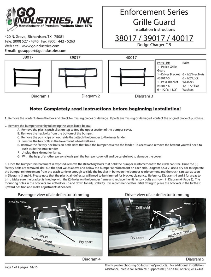
GO Industries 38017 installation instructions

GO Industries

GO Industries 38017 installation instructions

Cissell 30LBCMAN2 manual

Cissell

Cissell 30LBCMAN2 manual

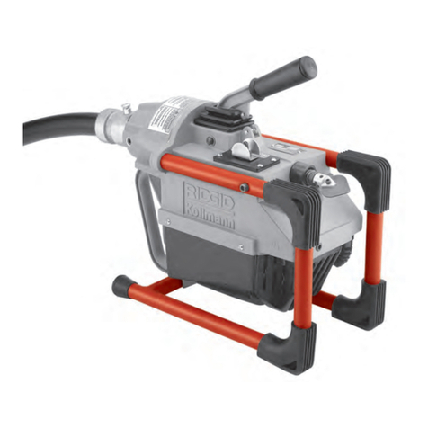
RIDGID K-60SP manual

RIDGID

RIDGID K-60SP manual

Gage Bilt GB751SH-5 Original instructions

Gage Bilt

Gage Bilt GB751SH-5 Original instructions

OVE SIERRA 60 installation manual

OVE

OVE SIERRA 60 installation manual

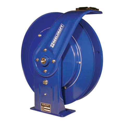
ReelCraft 7800 OLB21 operating instructions

ReelCraft

ReelCraft 7800 OLB21 operating instructions

Body Armor 4x4 ECO-SERIES user manual

Body Armor 4x4

Body Armor 4x4 ECO-SERIES user manual

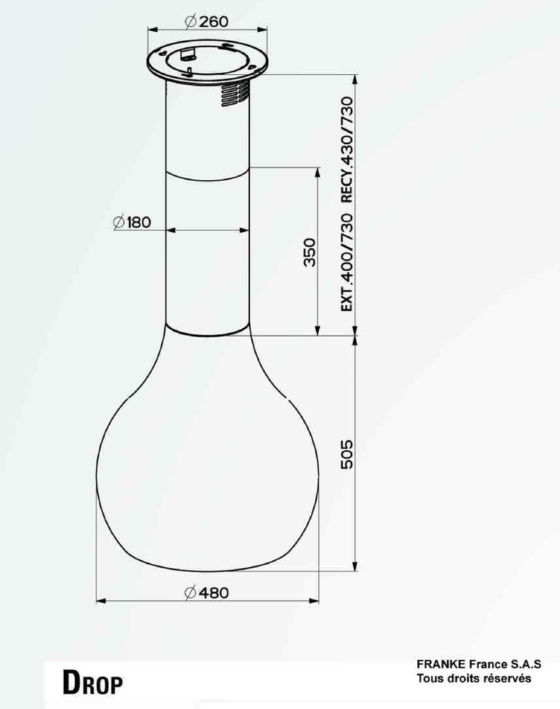
ROBLIN DROP Dimensions

ROBLIN

ROBLIN DROP Dimensions

MiniSolar MT-150 Assembling Guide

MiniSolar

MiniSolar MT-150 Assembling Guide

Parkside PSZ 250 B2 Operation and safety notes

Parkside

Parkside PSZ 250 B2 Operation and safety notes

ABB REM 610 Technical reference manual

ABB

ABB REM 610 Technical reference manual

Tyent ACE-13 user manual

Tyent

Tyent ACE-13 user manual

Parkside 55992 translation of original operation manual

Parkside

Parkside 55992 translation of original operation manual

manuals.online logo
manuals.online logoBrands
  • About & Mission
  • Contact us
  • Privacy Policy
  • Terms and Conditions

Copyright 2025 Manuals.Online. All Rights Reserved.

.700
.320
.155
.350
1.000
.875
General Operation
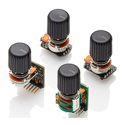
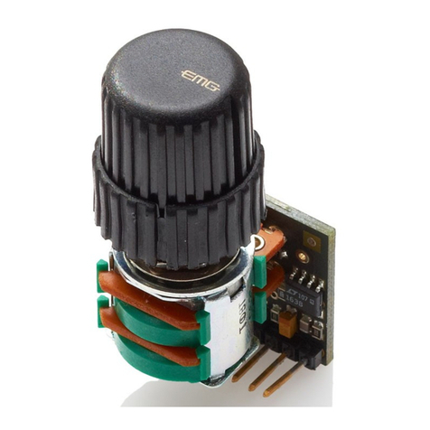
The B234rB is a stacked (concentric) set of 25K Ohm controls for EMG Active Pickup Systems. The top control functions as a volume control,
while the bottom control can be either another volume control, or by installing a shorting plug it can become a tone control. Examples are shown
in the included diagrams. The B234rB features plug-in compatibility with all EMG Pickup Systems. If necessary, you can solder existing pickup
cables to the wiper and ground contacts on the PC Board. If you need left handed operation (CCW) then contact EMG directly and we can supply
one for you. Also available is the B258rA-HZ for passive pickups (Green PC Board).
0230-0283rC
© 2013 Copyright EMG INC. All Rights Reserved.
PO BOX 4394
SANTA ROSA, CA
95402 USA
P (707) 525-9941
F (707) 575-7046
EMGPICKUPS.COM
1
2
3
4
5
6
Schematic Diagram:
B234rB Controls
(Both controls have a similar pinout)
IN/OUT
GND
IN/OUT
GND
IN/OUT
GND
CCW
W
CW
1
2
3
4
5
6
The EMG coax cables for wiring the guitar are a 2-pin pair,
The signal or “Hot” wire is White, the Ground (Shield) wire is Black.
A25K
VIEWED LOOKING AT
CONNECTOR PINS
BOTTOM
CONTROL
TOP
CONTROL
6543
SCHEMATIC NOTES:
The Schematic diagram above shows how each B234 Volume control is configured.
Pins 1 and 2 are the input or output of the CW (Clockwise) terminal of the control.
Pins 3 and 4 are the input or output of the W (Wiper) terminal of the control.
Pins 5 and 6 are duplicates of pins 1 and 2, the CW terminal (Clockwise).
Pins 2, 4, and 6 go directly to ground, the CCW (Counter-Clockwise) terminal of the control is grounded.
INSTALLATION INFORMATION
EMG MODEL: B234rB STACKED VOLUME CONTROLS
OR STACKED VOLUME/TONE CONTROLS
(ACTIVE PICKUP INPUT 25K OHM, BLACK PC BOARD)
Pickup Cable
Pickup Cable
Solder Pickup Hots to Input Pads
Solder Pickup Braids to GND Pads
The B234rB has solder pads that can be used
if you do not have connectors on the pickup
cables.
B234rB Page 2
6543
21
654321
Installation Instructions:
EMG Model: B234rB Stacked Volume or Volume/Tone (25K)
The B234rB has two controls that can be configured as two volume controls
or as a volume/ tone combination. Only the “B” Bottom Control can be used
as a tone control. The PC Board is marked with a “B” for the Bottom control
(larger outside control shaft) and “T” for the Top Control with the smaller, inner shaft.
The controls can be daisy-chained to produce a single output.
Both controls are 25K Ohm (Audio Taper) and are designed to work with EMG Active Pickups,
The diagrams included assume you have two pickups installed in your instrument.
Diagram #1
If you are using the two controls as volume controls the pickup inputs should be connected
to the “wiper” contacts of the pots, the middle two contacts.
Using the Wipers as the inputs will allow the controls to work independently of one another.
As shown in the diagram the output of each control comes from pins 5 and 6 on the left side
of each 6 pin header, they can also come from pins 1 and 2 which ever pair is more convenient.
Pins 1 and 2 are the same as pins 5 and 6.
Diagram #2
To use the Top control as a Volume and the Bottom control as a Tone Control simply install the
blue shunt onto the terminals as shown to the right. A capacitor has been pre-installed on the
circuit board. Once the shunt is in place it won’t be necessary to plug any
contacts onto the “B” 6 pin header. The shunt does all the work.
Assuming there are two pickups in your instrument, when you use
either tone control, both pickups will be effected. This is common
with passive style controls.
Pickup Inputs (Pins 3 & 4)
Top and Bottom
Pickup Outputs (Pins 5 & 6)
or (Pins 1 & 2))
Top and Bottom
Pickup Input
Pickup Output
- 9V +
BRIDGE PICKUP
OUTPUT
T
R
S
OUTPUT CABLE
TONE
BATTERY
BUSS
TONE
B124rH
NECK PICKUP
- 9V +
BRIDGE PICKUP
OUTPUT
T
R
S
OUTPUT CABLE
BATTERY
BUSS
NECK PICKUP
(T) TOP CONTROL
NECK PICKUP VOLUME
(B) BOTTOM CONTROL
BRIDGE PICKUP VOLUME
LOOPED CABLE
BOTTOM TO TOP
Diagram #4
Stacked Volume / Volume
Master Tone
Diagram #3
Daisy Chained
Volume Tone / Volume Tone
Diagram #1
Diagram #2