EMIT Limit Comparato User manual
EMIT WEST - 3651 Walnut Avenue, Chino, CA 91710 • (909) 627-8178 • Fax (909) 627-7449
EMIT EAST - One Colgate Way, Canton, MA 02021-1407 • (781) 821-8370 • Fax (781) 575-0172 • Web Site: www.DescoEMIT.com
TB-6566 Page 1 of 6 Revision June 2009
© 2009 DESCO INDUSTRIES INC.
Employee Owned
Limit Comparator - Instructions for Use
TECHNICAL BULLETIN TB-6566
Made in America
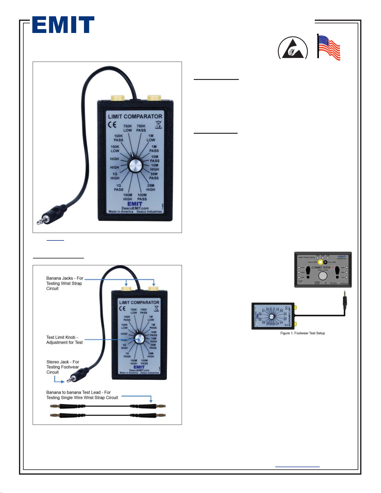
Item 50421 X3 Limit Comparator
DESCRIPTION
PACKAGING
1 Limit Comparator
2 Test Leads, Banana to Banana
1 NIST Certificate of Calibration
OPERATION
Testing Footwear Circuit, refer to figure 1.
To complete the footwear test, you will need to test the
low and high limits. Refer to the dipswitch setting on the
left side of the testers for footwear test ranges.
Manufacturer’s suggested default test range is 750K
low and 35Meg high for the US and Europe.
Do not power down tester, remove stereo cable from
bottom right jack of tester labeled “FOOTPLATE” and
connect the stereo lead from model 50421 to the jack
labeled “FOOTPLATE”.
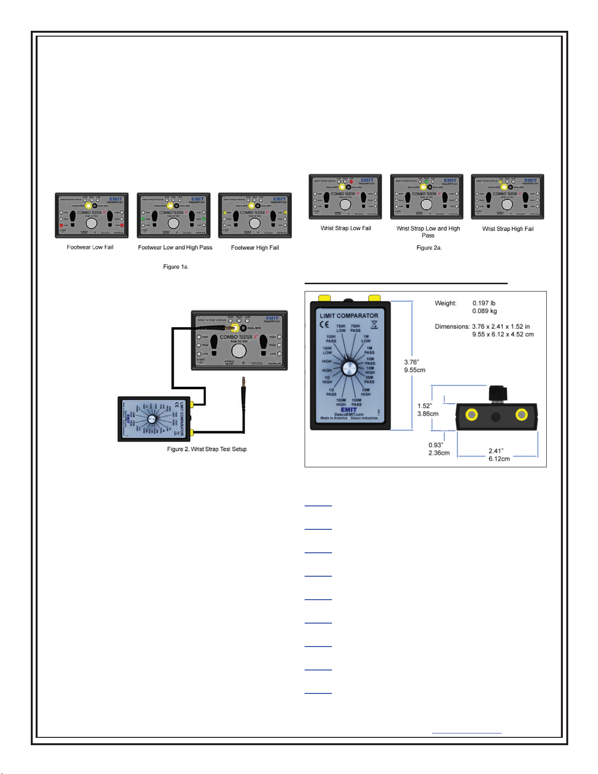
Testing Low Circuit – If the tester’s low range is set to
750K. Set the knob
on model 50421 to
the “750K LOW”
position. Touch the
TEST contact on
the tester and you
should get a red
LED for the left and
right foot. Disre-
gard the test result
for the wrist strap,
if the wrist strap
circuit is on.
Set the knob on model 50421 to “750K Pass”, touch the
TEST contact on the tester and you should get a green
LED for the left and right of the foot.
TB-6566 Page 2 of 6 Revision June 2009
© 2009 DESCO INDUSTRIES INC.
Employee Owned
EMIT WEST - 3651 Walnut Avenue, Chino, CA 91710 • (909) 627-8178 • Fax (909) 627-7449
EMIT EAST - One Colgate Way, Canton, MA 02021-1407 • (781) 821-8370 • Fax (781) 575-0172 • Web Site: www.DescoEMIT.com
Testing High Circuit – If the tester’s high range is
35Meg. Set the knob on model 50421 to “35M PASS”,
touch the TEST contact on the tester and you should
get a green LED for the left and right feet. Set the
knob on model 50421 to “35M HIGH”, touch the TEST
contact on the tester and you should get a yellow LED
for both the left and right feet. If the limit is set to 1Gig
on the tester, test at 1Gig on model 50421, same for
10Meg and 100Meg. Disregard the test result for the
wrist strap, if the wrist strap circuit is on.
Testing Wrist Strap Circuit, refer to figure 2
To complete
the wrist strap
test, you will
need to test
the low and
high limits.
Refer to the
dipswitch
setting on
the left side
of the testers
for wrist strap
test ranges.
Manufacturer’s suggested default test range is 750K
low and 10Meg high for the US and 750K to 35Meg for
Europe.
Do not power down the tester. Using the 2 banana
leads included with model 50421. Attach 1 of the
banana leads to the right side banana jack on model
50421 and connect the other end to the ground sym-
bol jack on the tester. Connect the last banana jack to
the left banana jack of model 50421 and the other end
to the “SINGLE – WIRE” banana jack. Note be sure
FOOTPLATE lead is removed.
Testing Low Circuit - If the tester’s low range is set to
750K. Set the knob on model 50421 to the “750K LOW”
position. Touch the TEST contact down on the tester
and you should get a red LED for the Wrist strap. Dis-
regard the test result for the footwear. Set the knob on
model 50421 to “750K Pass”, touch the TEST contact
on the tester and you should get a green LED for the
wrist strap.
Testing High Circuit – If the tester’s high range is
10Meg. Set the knob on model 50421 to “10M PASS,”
touch the TEST contact on the tester and you should
get a green LED for the wrist strap. Set the knob on
model 50421 to “10M HIGH”, touch the TEST contact
on the tester and you should get a yellow LED for the
wrist strap. If the limit is set to 35Meg on the tester, test
at 35Meg on model 50421. Disregard the test result for
the footwear.
SPECIFICATIONS AND DIMENSIONS
Charge Detection
When the operator is connected to the remote and
accumulates a voltage greater than ± 1.25 volts, the
CHARGE LED (red) will display in its respective OP-
ERATOR section (for charge detection data out, see
the Data Output section on Page 8). To disable charge
detection on the display, shunt jumper JP6 inside the
unit (See Page 7). If a charge is detected while using
this configuration, the display will remain in its previous
state until the charge is no longer detected.
Testers limit comparator will calibrate:
50404 - Dual Independent Footwear Tester,
Foot Plate,120V
50412 - Dual Independent Footwear Tester, No Adapter,
CE, Bin
50407 - Dual Independent Footwear and Wrist Strap
Tester, USA Standard
50413 - Dual Independent Footwear and Wrist Strap
Tester, Euro Standard
50562 - Dual Independent Footwear and Wrist Strap
Tester, Dual Foot Plate, Euro Standard
50430 - SmartLog X3, w/Dual Foot Plate, Keypad &
Barcode Reader, Software, 120V
50431 - SmartLog X3, w/Dual Foot Plate, Keypad &
Barcode Reader, No Software, 120V
50432 - SmartLog X3 w/Dual Foot Plate, Keypad, &
Barcode Reader, Euro Specs
50434 - SmartLog X3 w/Dual Foot Plate, Laser
Scanner, Software, Euro Specs, CE Approved

EMIT WEST - 3651 Walnut Avenue, Chino, CA 91710 • (909) 627-8178 • Fax (909) 627-7449
EMIT EAST - One Colgate Way, Canton, MA 02021-1407 • (781) 821-8370 • Fax (781) 575-0172 • Web Site: www.DescoEMIT.com
TB-6566 Page 3 of 6 Revision June 2009
© 2009 DESCO INDUSTRIES INC.
Employee Owned
50421 LIMIT NOMINAL
RESISTANCE % TOLERANCE
OF NOMINAL
RESISTANCE
100K FAIL LOW 89K ±2%
100K PASS 110K ±2%
750K FAIL LOW 675K ±2%
750K PASS 825K ±2%
1M FAIL LOW 909K ±2%
1M PASS 1.10M ±2%
10M PASS 9.09M ±2%
10M FAIL HIGH 11.09M ±2%
35M PASS 31.09M ±2%
35M FAIL HIGH 37.89M ±2%
100M PASS 90.9M ±2%
100M FAIL HIGH 112.9M ±2%
1G PASS 912.9M ±2%
1G FAIL HIGH 1.113G ±2%
Limited Warranty
EMIT expressly warrants that for a period of five (5) years
from the date of purchase, EMIT Limit Comparators will be
free of defects in material (parts) and workmanship (labor).
Within the warranty period, a credit for purchase of replace-
ment EMIT products, or, at EMIT’s option, the product will
be repaired or replaced free of charge. If product credit is
issued, the amount will be calculated by multiplying the un-
used portion of the expected five year life times the original
unit purchase price. Call our Customer Service Department
at 909-627-8178 (Chino, CA) or 781-821-8370 (Canton,
MA) for a Return Material Authorization (RMA) and proper
shipping instructions and address. Please include a copy
of your original packing slip, invoice, or other proof of date
of purchase. Any unit under warranty should be shipped
prepaid to the EMIT factory. Warranty replacements will take
approximately two weeks.
Warranty Exclusions
THE FOREGOING EXPRESS WARRANTY IS MADE
IN LIEU OF ALL OTHER PRODUCT WARRANTIES,
EXPRESSED AND IMPLIED, INCLUDING MERCHANT-
ABILITYAND FITNESS FOR A PARTICULAR PURPOSE
WHICH ARE SPECIFICALLY DISCLAIMED. The express
warranty will not apply to defects or damage due to acci-
dents, neglect, misuse, alterations, operator error, or failure
to properly maintain, clean or repair products.
Limit of Liability
In no event will EMIT or any seller be responsible or liable
for any injury, loss or damage, direct or consequential, aris-
ing out of the use of or the inability to use the product. Be-
fore using, users shall determine the suitability of the product
for their intended use, and users assume all risk and liability
whatsoever in connection therewith.
50730 - SmartLog X3, Solid State, Keypad, Reader,
Software, 120V
50731 - SmartLog X3, Solid State, Keypad, Reader,
No Software, 120V
50732 - SmartLog X3, Solid State, Keypad, Reader,
Software, Asia
50733 - SmartLog X3, Solid State, Keypad, Reader,
No Software, Asia
50734 - SmartLog X3, Solid State, Laser Scanner,
Software, Euro
50735 - SmartLog X3, Solid State, Laser Scanner,
No Software, Euro
50420 - SmartLog X3 Footwear & Wrist Strap Tester
CALIBRATION
There are no user adjustments on model 50421. Each
value is a fixed resistor load, any model 50421 that falls
out of specification will need to be sent to factory for
repair. Using a DVM (digital voltmeter), set the meter
to read ohms. The limit that the knob is set on can be
measured using the DVM connected between Banana
1 to Banana 2 and connected between Conductor 1
and Conductor 2. Refer to figure 3.
Table of contents
Other EMIT Test Equipment manuals

EMIT
EMIT 50512 Service manual

EMIT
EMIT 50557 Installation guide

EMIT
EMIT SmartLog V4 Installation and operating instructions

EMIT
EMIT TB-6568 Installation guide

EMIT
EMIT eScan2 User manual

EMIT
EMIT ESD Glove Test Fixture Installation and operating instructions

EMIT
EMIT SmartLog V5 Service manual

EMIT
EMIT SmartLog V5 Installation and operating instructions


