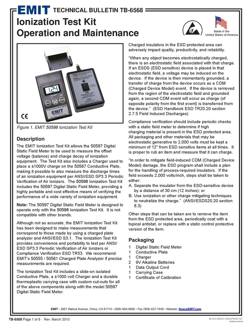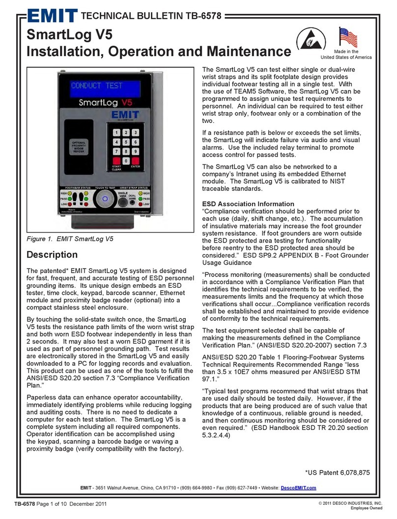
TB-6520Page3of7
Surfaceresistanceohmvaluesareexpressedwitha
mantissaandexponentorpowerofthenumber.For
example,if“8”isilluminatedbyitsLEDandtheLCD
displaysamantissaof“7.14”,themeasurementis7.14x
10E8 ohms or 714,000,000 ohms
If surface is over 10E12 ohms, the following will appear:
• “1____”ontheLCDdisplayindicateOverrangeorthatthe
readingexceedsthedisplaycapabilities
C. Test Button: This red button activates electrical power
totheMeter.Theexponentorpowerofthenumberis
displayed immediately with LED illuminating number. If “8”
is illuminated, the measurement is in the 108or 10E8 ohm
range. To make a measurement in accordance with
ANSI/ESDS4.1,thebuttonistobedepressedfor10-20
seconds for the unit to make numerous readings and
calculations. (Testing in accordance with ANSI/ESD S4.1
requires15secondsofelectrification;incontrast,most
analog type meters display measurements instantaneously.)
The LCD will display temperature (F), then temperature
(C), then relative humidity, and then the surface resistance
mantissa.Forexample,iftheLCDdisplaysamantissaof
“7.14”, and “8” is illuminates by its LED, the measurement is
7.14x10E8 ohms or 714,000,000 ohms.
Duringtheentireperiod,surfaceresistanceexponentwillbe
displayed by LED illuminating number.
D. Override Test Voltage Button:Wheninthe“up”
position, during resistance portion of test, Meter will
automatically switch to the correct voltage for the resistance
range. LED will illuminate noting selected voltage.
Material10E5 ohms or less should be measured at 10
volts.Material10E6ohmsorgreatershouldbetested
at 100 volts. The button is a switch, which if depressed
will override automatic voltage selection and test will be
performed at 10 volts regardless of resistance level.
E. Jacks:OneendofTestLeadshas3.5mmplug(fits
Meterleftjack).The3.5mmplugisshielded(identified
byinsulatedtipandbarrelblacklead)-seeRTGtest
procedure: Per ANSI/ESD S4.1 “The sensing lead of the
resistance meter shall be connected to groundable point.”
OneendofTestLeadhasstandardbananaplug(fits5#
Electrode jack).
F. AA Battery Compartment.
G. Resistivity Parallel Electrodes Attachment.
(optional Item number 50560)
Cleaning
Per ANSI/ESD S4.1 “Clean the electrodes with a minimum
70%isopropanol-watersolution.”Makesureconductive
pads are dry prior to use.
See specific product test standard for test lab specimen
cleaninginstructions.PerANSI/ESDS4.1Worksurfaces
“The test specimens and electrodes shall be cleaned twice
withaminimum70%isopropanol-watersolutionusinga
clean,low-lintingclotheachtime.”(Note:thenconditioned
for 72 hours, minimum).
For installed product periodic testing, do not clean surfaces.
However, if any measurements lie outside acceptable
range,thencleanthesurfaceandre-test(Note:for
worksurfaces, use an ESD cleaner not containing silicone).
Besurethesurfaceisdrybeforetesting.
Periodic maintenance-Theareasurroundingthecable
jacks at the top end of the meter should be wiped with a
clean cloth moistened with alcohol to remove skin oils that
will accumulate and affect the accuracy at high resistances.
Thefrequencyofcleaningwilldependonusage;oncea
monthwouldbeagoodstartingpoint.Otheritemsthat
should also be cleaned in this fashion are the cable jackets
and the resistivity attachment, if included.
Power Requirements
The Meter is powered by two replaceable alkaline AA
batteries.
Battery Replacement
Depress buttons on both sides of bottom end cap of meter
housing. Remove cap, press on right edge of protruding
battery door, unlatching it, and swing door open. Carefully
replace batteries with alkaline Type AA. Polarity must be
correct or damage may occur. Close battery door and
re-installbottomendcaponmeterhousing.
Test Procedure
General Guidelines:
• Useboth5PoundElectrodesforRTT
• Useone5PoundElectrodeandblacksensingleadto
equipment ground to groundable point for RTG
• UseoptionalResistivityAttachment(removingleads&
electrodes) for Resistivity measurements
• Ensurethatitembeingmeasurediselectricallyisolated
(i.e. placed on an insulative surface) as Meter will
measure lowest resistance path
• EnsurethattestleadsareseparatedorMetermay
measure lower resistance path
• Whenusing5PoundElectrodes:
• Placenocloserthan2"fromedgeofsurfacebeing
measured.
• Placenocloserthan3"toanygroundablepoint
• Place5PoundElectrodesabout10"apartforRTTof
worksurfacesandabout3'apartforRTTofflooring.
• Preferredplacementsinclude:mostcommonlyused
surface portion, most worn, center, and furthest from
groundable point.
• Ifsurfacehassections(likefloortilesorgarmentpanels),
forRTTplacea5poundelectrodesondifferentsections
• CleansurfaceforTestLab,butdonotinitiallyclean
surface for installed products (if fails, clean and retest).
• OnlyuseanapprovedESDcleanerandallowtodryprior
to testing.
• LayMeteronsurface;holdinginhandcancause
measurent distortions.
©2010DESCOINDUSTRIESINC.
EmployeeOwned
EMIT-3651WalnutAvenue,Chino,CA91710•(909)664-9980•Fax(909)627-7449•Website:DescoEMIT.com


