1.PREFACE............................................................................................................................................
2.INSTALLATION....................................................................................................................................
3.ELECTRICAL WIRING........................................................................................................................
1.1 GENERAL SPECIFICATIONS
1.2 ORDERING INFORMATION
2.1 GENERAL DESCRIPTION
2.4 PANEL CUT-OUT
2.5 ENVIRONMENTAL RATINGS
2.6 PANEL MOUNTING
2.7 INSTALLATION FIXING CLAMP
2.8 REMOVING FROM THE PANEL
3.1 TERMINAL LAYOUT AND CONNECTION INSTRUCTIONS
3.4 SUPPLY VOLTAGE INPUT CONNECTION OF THE DEVICE
3.7 ALARM OUTPUT CONNECTIONS
3.7.1 RELAY OUTPUT CONNECTION
1.3 WARRANTY
1.4 MAINTENANCE
2.2 FRONT VIEW AND DIMENSIONS OF ESM-3700 DIGITAL PROCESS INDICATOR
WITH ALARM OUTPUT
2.3 FRONT VIEW AND DIMENSIONS OF ESM-3700 DIGITAL PROCESS INDICATOR
WITHOUT ALARM OUTPUT
3.2 ELECTRICAL WIRING DIAGRAM
3.3 VIEW OF THE DEVICE LABEL
3.5 PROCESS INPUT CONNECTION
3.5.1 PROCESS INPUT CONNECTION OF SERIAL TRANSMITTER WITH CURRENT
OUTPUT (LOOP POWERED)
3.5.2 PROCESS INPUT CONNECTION OF 3-WIRE TRANSMITTER WITH CURRENT
OUTPUT
3.5.3 PROCESS INPUT CONNECTION OF TRANSMITTER WITH VOLTAGE OUTPUT
3.6. GALVANIC ISOLATION TEST VALUE OF ESM-3700 DIGITAL PROCESS INDICATOR
3.7.2 SSR DRIVER OUTPUT CNNECTION
4.1 FRONT PANEL DEFINETION OF DEVICE WITH ALARM OUTPUT
4.2 FRONT PANEL DEFINETION OF DEVICE WITHOUT ALARM OUTPUT
4.3 OBSERVATION OF THE SOFTWARE REVISION ON THE DISPLAY
4.4 CHANGING AND SAVING ALARM SET VALUE
4.5 PROGRAMMING MODE PARAMETER LIST
4.6 OPERATION GRAPHICS OF ALARM OUTPUT AND ALARM TYPES
4.7 EASY ACCESSING DIAGRAM OF PROGRAMMING MODE PARAMETERS
4.7.1 DEVICE WITH ALARM OUTPUT
4.7.2 DEVICE WITHOUT ALARM OUTPUT
4.8 ENTERING TO THE PROGRAMMING MODE, CHANGING AND SAVING PARAMETERS
4. FRONT PANEL DEFINETION AND ACCESSING TO THE MENUS..............................................
5.DISPLAY FUNCTIONS........................................................................................................................
6.UNIVERSAL INPUT USER READING ADJUSTMENT OPERATION.................................................
7.FAILURE MESSAGES IN ESM 3700 DIGITAL PROCESS INDICATOR............................................
8.SPECIFICATIONS................................................................................................................................
9.OTHER INFORMATIONS....................................................................................................................
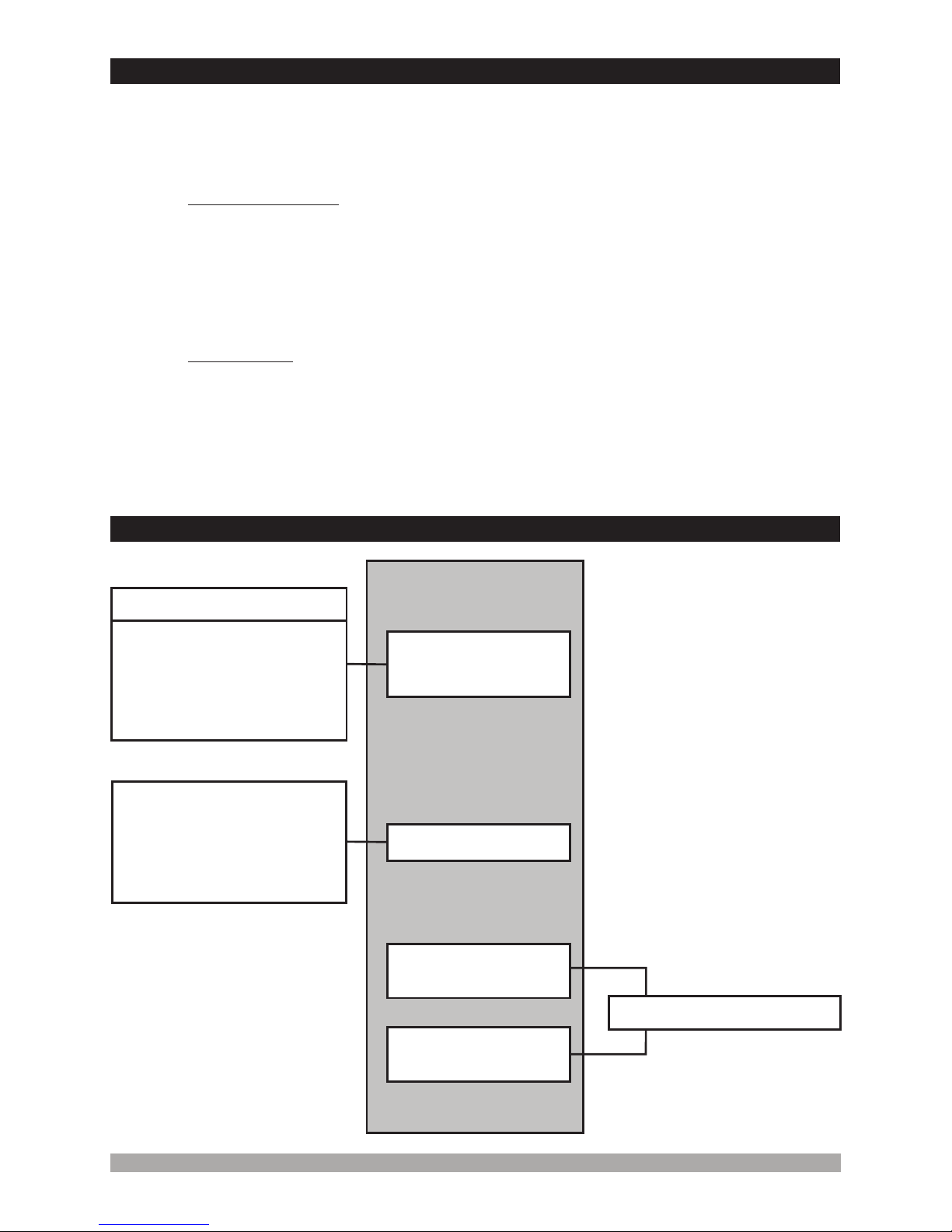
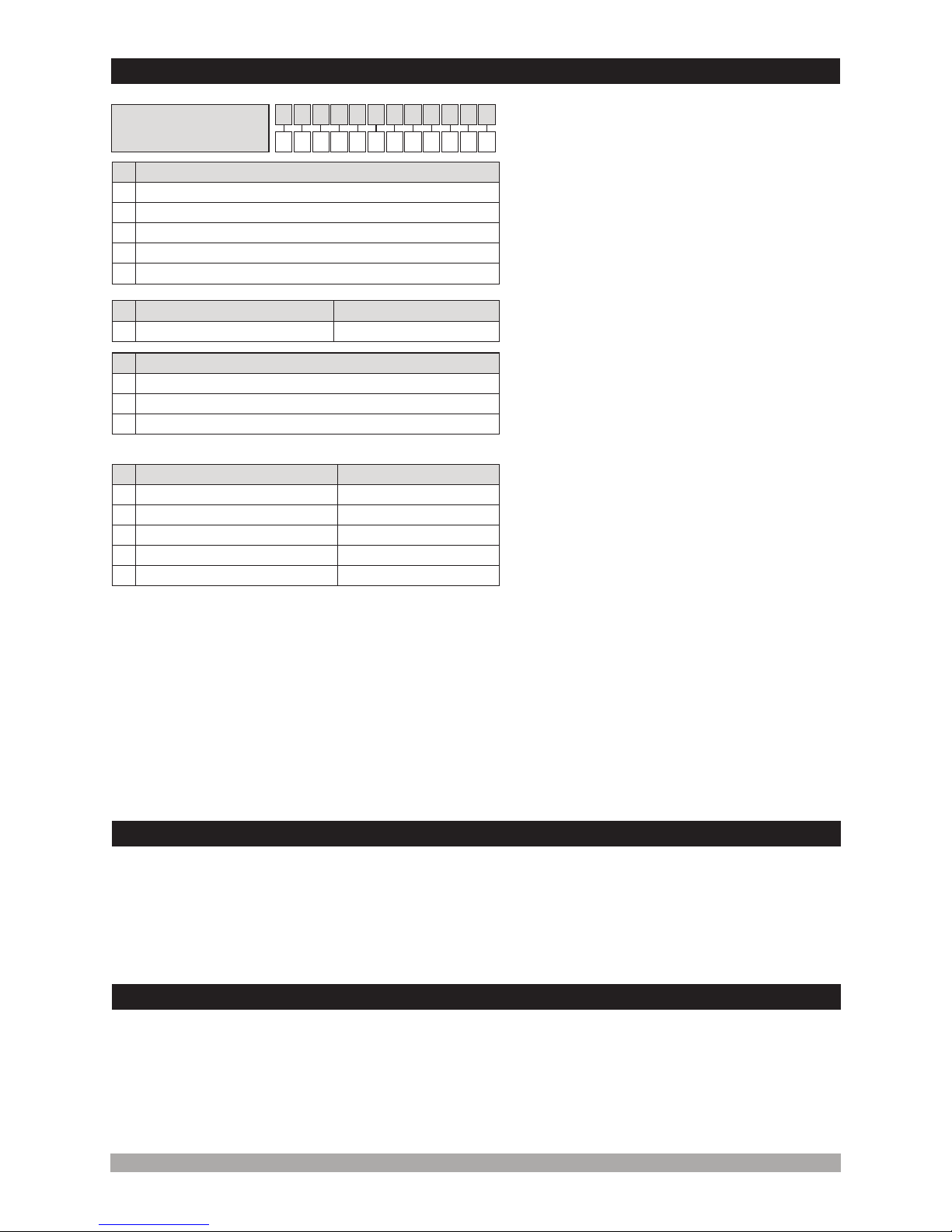
Contents
Page 5
Page 31
Page 19
Page 12
Page 7
Page 29
3
Page 28
Page 32
Page 33