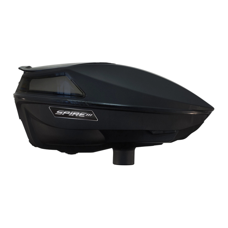
Empire Scion User manual

EMPIRE® SCION™ LOADER INSTRUCTIONS
Battery Installation
• Removethetoollessbatterydoorbyslidingthetabtowardthenoseandliftthedoorupand
outoftheloader.
• Removethebatteryholder,byrstremovingthebatterywireconnector.
•Install(6)AAbatteriesfollowingthepolaritymarkingsontheholder.Batteriesnot
included.
•Connectbatterywireconnectortothebatterypack.
•Reinstallthebatterypack.Makesurethewireisnotbetweenthebatterypackand
compartment.Wireshouldbetotheside.
•Reinstallthetoollessbatterydoor.
Attaching the Loader
Straightfeedneckapplication:theloaderwillloaddirectlyintothefeedneck(theloader
neckcanbeshapedwithsandpaperiftheneckistoowidetotintoyourmarker).Pressthe
Scion™loaderintothefeedneckuntilitstops:aligntheloaderparallelwiththemarkerwith
thelidtowardstherearofthemarker.
Loading the Loader
•Holdtheloaderfromtheback,withyourthumbunderthelipofthelid.
•Sweepingyourthumbupwardwillpopthelidopen.
•Loadpaintballsandclosethelid.Leavespacefortheballstomoveabout.
OPERATING THE EMPIRE® SCION™
YourEmpire®Scion™loaderusesaseriesofsensorsandcontrolsystemstogivefast,
consistentfeedingspeedswhilebeingverygentleonpaintballs.Whentheloaderisturnedon
itwillimmediatelystartfeedingpaintballs.Iftheloaderisemptyitwillcontinuetorun,butat
aslowerspeedtoallowpaintballstoorganizewithinthecarrier.TheloaderusestheBreak
BeamInfraredSensorinthefeednecktodetectshotsredandquicklydeliverpaintballsto
themarker.TheDriveSensorSystemmakessurethatregardlessofthebatteryvoltage,the
loaderwillfeedatthesamespeedsotheuserwillnotseeagradualdecreaseinperformance
asthebatteryisdischarged.Theloaderwillindicatetotheuserwhenthebatteryhasbeen
dischargedandneedstobechanged.TheEmpire®Scion™alsousesthesesystemstodetect
ajaminthesystem(explainedbelow)andtoclearthejamefciently.
ACTIVATING THE LOADER:
Turning On:
PressandholdthePowerButton,theLEDwillturnRED.ReleasethePowerButtonwhenthe
LEDturnsGREEN.
Turning Off:
PressandholdthePowerButtonuntiltheLEDglowsRED.ReleasePowerButton,loaderis
nowOFF.
Low Battery Indication:
IftheBatteryislow,theLEDwillblinkREDwhiletheloaderisidling(notspinning).Ifthe
BatteryisOKtheLEDwillblinkGREEN.
Auto Anti-jam:
Iftheloaderseesmorethat2consecutiveshotsredanddoesnotfeedaball,theloader
willattempttoclearajam.Theloaderwilltrytoclearthejamupto5timesbeforeresuming
normaloperation.TheLEDwillturnORANGEwhenattemptingtoclearajam.
Quick Activate:
IftheloaderisONandidleitmaybestartedagainbyquicklypressingandreleasingthePower
Button.
PROGRAMMING:
To Enter Programming Mode:
WiththeloaderOFF,pressandholdthePowerButtonuntiltheLEDrapidlyalternatesRED
andGREEN,thenrelease.TheloaderwillstopontheGREENlight.ReleasethePowerButton
andtheloaderisnowreadytoprogram.
To Exit Programming Mode:
Afterapproximately5secondsofinactivitytheloaderwillshutOFF.

Settings in Programming Mode:
•YourEmpire®Scion™loadersystemhas6MotorSpeeds(1=slowest,6=fastest).To
changetheMotorSpeedsettings,rstenterProgrammingMode(directionsnotedabove),
theLEDwillturnGREEN.ThiswillindicateyouhaveselectedtheMotorSpeedsetting.
PressandholdPowerButton.TheLEDwillbeginblinkinganumberoftimesandwillbe
equaltothecurrentsetting.Oncenishedblinking,pressandreleasethePowerButtona
numberoftimesequaltothenewdesiredsetting,thenwait.Afterashorttimeofinactivity
theLEDwillrapidlyashGREENandREDtoindicatethesettinghasbeensaved.
• SelfTest–indicatedbyanORANGELED. IMPORTANT: WHEN RUNNING SELF TEST,
THE LOADER SHOULD NOT BE INSTALLED ON A MARKER AND THERE SHOULD BE
NO PAINTBALLS PRESENT IN THE LOADER.Thissettingwillactivatetheloader’sself
testingfeaturetocalibratetheonboardsensorsandhelptheuseridentifyproblems.(To
startself-test,rstentertheProgrammingModeasdescribedabove.Tapandrelease
PowerButtonuntilORANGELEDisdisplayed.PressandholdthePowerButton,theLED
willturnOFF,releasethePowerButtonandtheselftestwillstart.(See“SelfTest”section
forfullexplanation)
SELF TEST:
IMPORTANT: WHEN RUNNING A SELF-TEST THE LOADER SHOULD NOT BE IN-
STALLED ON A MARKER AND THERE SHOULD BE NO PAINTBALLS PRESENT IN THE
LOADER.Theself-testismeantasawaytheusercandiagnoseanyissuewiththeloader
quickly.Theself-testfeaturewillperform3testsdescribedbelow.Note–alwayscheckthat
fresh,brandnamealkalineorlithiumbatteriesareinstalledwhenrunningself-test.Forbest
resultsuse6AA’sduringselftest.
Test 1 – Drive Sensor Test
ThisdiagnosticteststheDriveSensorSystemwhichcontrolsthespeedoftheloaderandde-
tectsjamsinthesystem.TheLEDwillblinkORANGEonetimetoindicateTest#1hasstarted.
Theloaderwillthenspinforashortamountoftimetotestthedrivesensor.Aftertheloader
stopsspinningtheLEDwillturneitherGREENorREDtoindicatethetesthaspassedor
failedrespectively.AGREENLEDequalspassingandREDequalsfailing.Thistestwillrunup
to3times.Ifitfailsafter3timesitwillmoveontothenexttest.Ifall3attemptsfail,theLED
willblinkRED3timesafterthelastattempt.
Test 2 – Feedneck Break Beam Sensor Test
ThisdiagnosticteststhattheFeedneckBreakBeamSensorSystemisworking.TheLEDwill
blinkORANGEtwotimestoindicateTest#2hasstarted.DuringTest#2theloaderwillnot
spin.WhenthetestisnishedtheLEDwillindicateGREENorREDifthetestpassesorfails
respectively.Thistestwillonlyattemptonetime.
Test 3 – Motor Control System Test
ThisdiagnostictestindicatestotheuserwhetherornottheMotorControlSystemisfunction-
ingproperly.TheLEDwillblinkORANGEthreetimestoindicateTest#3hasstarted.During
thetesttheloadershouldspinrstforward,theninreverseforequalamountsoftime.After
thetesttheLEDwillindicateGREENorREDifthetestpassesorfailsrespectively.Thistest
willonlyattemptonetime.AfterTest#3theLEDandloaderwillturnOFF.
NOTE:
•The battery wire connector is a 9V-type connector, but 9V batteries do not have
sufficient power. Only use 6-AA batteries installed in the supplied battery holder.
4-AA battery adapter sold separately.
• NEVERuseunauthorizedrechargeablebatterypacksinplaceofthesupplied6-AA
batteryholder.Theelectroniccomponentsarenotdesignedtohandlethehighoutput
ofsomerechargeablebatterypacks.Theuseofunauthorizedrechargeablepacks
posesarehazardandriskofinjury,andwillvoidyourwarranty.
• DonotuserechargeableAAbatteries.Theyhavelessvoltagethanalkalinebatteries
anddonotprovideenoughpower.
• NEVERattempttomodifytheelectroniccomponents,wiring,orbatteryconnector.
Doingsoposesarehazardandriskofinjury,andwillvoidyourwarranty.

CHARGEUR EMPIRE® SCION™: INSTRUCTIONS
Mise en place des piles
• Enlevezlaportetoollessdebatterieenglissantl’étiquetteverslenezetsoulevezlaporte
verslehautethorsduchargeur.
• Retirezlesupportenayantpritsoind’avoirretireleslsconnecteursauparavant.
•Installezlesbatteries6AAsuivantlesinscriptionsdepolaritésurlesupport.
•Reconnectezleslsconnecteurssurleblocpile.
•Réinstallezlepaquetdebatterie.Assurez-vousqueleln’estpasentrelepaquetdebat
terieetlecompartiment.Leldevraitêtreaucôté.
•Réinstallezlacoquemanuellement.
Installation du chargeur
Lechargeursemontedirectementsurlegoulot(legoulotduchargeurpeutêtreponcéà
l’aidedepapierabrasifsicelui-ciesttroplarge.EnfoncezlechargeurScion™àfond:alignez
lemarqueuretlechargeurdefaçonparallèle,couvercledirigéversl’arrièredumarqueur.
Chargement des billes
•Tenezlechargeurparl’arrière,avecvotrepoucesurleborddelacoque.
•Toutenappuyant,faitesglisservotrepouceverslehaut;lecouvercleetilsauteraet
resteraouvert.
•Chargezlesbillesetfermezlecouvercle.Laissezdelaplacepourquelesbillespuissentse
déplacer.
MISE A FEU DE L’EMPIRE® SCION™
VotrechargeurEmpire®Scion™estéquipédplusieurssystèmesdecontrôleetdecapteurs
andepermettreunealimentationrapideetrégulièretoutenpréservantlesbilles.
L’alimentationenbillessedéclenchedèsl’activationduchargeur.Silechargeurestvide,
celle-cicontinuemaisàunevitessemoindreandepermettreauxbillesdesemettreen
place.LechargeurestéquipédusystèmeBreakBeamInfraredSensorauniveauducoude
d’alimentationquipermetdedétecterlestirsmettreainsirapidementenplacelesprochaines
billesdanslemarqueur.LesystèmeDriveSensorpermetdebénécierd’unealimenta-
tionrégulièreenbille,quellequesoitleniveaudechargedespiles.Lechargeuravertira
l’utilisateurdufaibleniveaudechargedespilesetdelanécessitédeleurremplacement.
Cessystèmespermettentégalementàl’Empire®Scion™dedétecteretévitertoutenrayage
(voirci-après).
ACTIVATION DU CHARGEUR:
Activation:
MaintenezleboutonPowerenfoncé,laLEDs’allumeenROUGE.Relâchezleboutonunefois
laLEDpasséeauVERT.
Désactivation:
MaintenezleboutonPowerenfoncéjusqu’àcequelaLEDsoitROUGE.Relâchezlebouton,le
chargeurestdésactivé(OFF).
Indications de niveau de charge des piles:
Sileniveaudechargedelapileestfaible,laLEDclignoteraROUGElorsquelechargeuresten
attente(pasderotation).SilachargedelapileestOK,laLEDclignoteraVERT.
Auto Anti-enrayage:
Silechargeurcapteplusdedeuxtirsconsécutifsetn’alimentepasdebille.Undispositif
anti-enrayagesemettraenplaceandetenterdedégagerlesbilles.Cettetentativepeutse
répéterjusqu’àcinqfoisavantdefonctionnerànouveaunormalement.LaLEDpasseraà
l’ORANGElorsd’unetentativededégagementdebilles.
Activation rapide:
Silechargeuretactivé(modeON)etqu’aucunealimentationn’alieu,vouspouvezleréactiver
rapidementenpressantpuisrelâchantrapidementleboutonPower.
PROGRAMMATION:
Pour accéder au mode de Programmation:
Chargeurdésactivé,maintenezaleboutonPowerenfoncéjusqu’àcequelaLEDalterne
rapidementduROUGEauVERT,puisrelâchez.LaLEDduchargeurresteVERTE.Relâchezle
boutonPoweretlechargeurestmaintenantprêtàêtreprogrammé.
Quitter le Mode de Programmation:
Aprèsapproximativement5secondesd’inactivité,lechargeursedésactivecomplètement.

Réglage du Mode de programmation:
•VotrechargeurEmpire®Scion™loaderpossède6vitessesmoteur(1=laplusbasse,6
=laplusélevée).Pourpasserd’unevitesseàuneautre,accédeztoutd’abordauModede
Programmation(voirconsignesci-dessus),laLEDpasseauVERT.Ceciindiquequevous
venezdesélectionnerleModedeRéglagedeVitesse.MaintenezleboutonPowerenfoncé.
LaLEDcommenceraàclignoteruncertainnombredefoisetseraégaleàl’arrangement
courant.Unefoislesclignotementsterminés,pressezpuisrelâchezleboutonPower
autantdefoisqueleniveaudevitessequevousdésirez,puispatientez.Aprèsquelques
secondesd’inactivité,laLEDclignoterarapidementVERTetROUGEpourindiquerquele
nouveauréglageaétésauvegardé.
• Diagnostique–LEDORANGE.IMPORTANT: LORSQUE VOUS PROCEDEZ A UN
DIAGNOSTIQUE, LE CHARGEUR NE DOIT PAS ETRE FIXE A UN MARQUEUR ET DOIT
ETRE VIDE.Ceréglageactivelescaractéristiquesdediagnostiqueduchargeuretpermet
àl’utilisateurded’identiercertainsproblèmes.(Pourprocéderaudiagnostique,accédez
d’abordauModedeProgrammation,commeindiquéprécédemment).Appuyezbrièvement
duleboutonPowerjusqu’àcequelaLEDsoitORANGE.MaintenezleboutonPower
enfoncéetlaLEDs’éteint,relâchezleboutonPoweretlediagnostiquecommencera.(voir
lapartie«Diagnostique»pourplusd’explications).
DIAGNOSTIQUE:
IMPORTANT: LORSQUE VOUS PROCEDEZ A UN DIAGNOSTIQUE, LE CHARGEUR NE
DOIT PAS ETRE FIXE A UN MARQUEUR ET DOIT ETRE VIDE.Lediagnostiquepermetà
l’usagerderéparerrapidementsonchargeur.Lediagnostiquepermetderéalisertroistests
décritsci-dessous.Remarque–vérieztoujoursquelespiles(alcalineoulithium)sont
neuvesetdequalitélorsquevousprocédezàundiagnostique.Pourdemeilleursrésultats,
utilisez6AA’slorsdudiagnostique.
Test 1 – Test du Drive Sensor (Système de capteur de guide)
CediagnostiquetestelesystèmeDriveSensorquicontrôlelavitesseduchargeuretdétecte
lesenrayagesdanslesystème.LaLEDclignoteunefoisORANGEpourindiquerqueletest1
adébuté.LechargeurtournependantquelquesinstantspourtesterleDriveSensor.Unefois
quelechargeurs’arrêtedetourner,laLEDpassesoitauVERT,soitauROUGEpourindiquer
queletests’estdéroulé,respectivement,avecsuccèsoupas.UneLEDVERTEsignieque
letestestunsuccès,uneROUGE,queletestestunéchec.Thetestsefaitrépète3fois.
S’iléchoueàlatroisièmetentative,ilpasseautestsuivant.Siles3testséchouent,laLED
clignote3foisaprèsledernieressai.
Test 2 – Test du Feedneck Break Beam Sensor (Système de capteur anti-coupe)
CediagnostiquevériequelesystèmeFeedneckBreakBeamSensorfonctionne.LaLED
clignoteORANGEdeuxfoispourindiquerqueletestàdébuté.Pendantletest2,lechargeur
netournepas.Quandletestestterminé,laLEDpasseauVERTouauROUGEpourindiquer
queletests’estdéroulé,respectivement,avecsuccèsoupas.Cetestneserépètepas.
Test 3 – Test du Motor Control System (système de contrôle moteur)
Cediagnostiquepermetàl’usagerdevérierqueleMotorControlSystemfonctionnecor-
rectement.LaLEDclignoteORANGEtroisfoispourindiquerqueletest3adébuté.Pendant
cetest,lechargeurtourned’abordenavantpuisenarrière,pendantlamêmedurée.Quandle
testestterminé,laLEDpasseauVERTouauROUGEpourindiquerqueletests’estdéroulé,
respectivement,avecsuccèsoupas.Cetestneserépètepas.Unefoisletest3réalisé,le
chargeursedésactive.
REMARQUE:
•Le connecteur de pile est un connecteur de type 9V, mais les piles 9V ne sont pas
assezpuissantes.N’utilisezquedespiles6-AAbatteriesinstalléesdanslesupport.
Adapteurdelabatterie4-AAvenduséparément.
• N’utilisezJAMAISdeblocspilesrechargeablesàlaplacedusupportdepiles6-AA
quivousestfourni.Lescomposantsélectroniquesnesontpascompatiblesavecles
blocspilesrechargeables.Leurutilisationreprésenteunrisqued’incendieoudebles
sureetannulevotregarantie.
• N’utilisezpasdepilesrechargeablesAA.Ellesontunvoltageplusfaiblequelespiles
alcalinesetnefournissentpasassezdepuissance.
• NetentezJAMAISdemodierlescomposantsélectroniques,connecteursouautres
câbles.Cecireprésenteunrisqued’incendieoudeblessureetannulevotregarantie.

INSTRUCCIONES PARA EL CARGADOR DEL EMPIRE® SCION™
Instalación de la Batería
• Quitelapuertatoollessdelabateríadeslizandolalengüetahacialanarizylevantela
puertaencimayfueradelcargador.
• Extraigaelsoportedelasbateríasdesconectandoprimeroelcableconector.
•Instalelasbaterías6AAquesiguenlasmarcasdelapolaridadenelsostenedor.
•Conecteelcabledelabateríaalpaquetedebaterías.
•Reinstaleelpaquetedelabatería.Cercióresedequeelalambrenoestéentreelpaquete
delabateríayelcompartimiento.Elalambredebeestarallado.
•Volverainstalarlacompuertadelpaquetedebaterías(noserequierenherramientas).
Instalando el Cargador
Instalacióndirectaenelcuellodealimentación:elcargadorsecolocarádirectamenteal
cuellodealimentación(alcuellodelcargadorselepuededarformaconpapeldelijasies
muyanchoparacaberenlaentradadesumarcador).PresioneelcargadorScion™dentrodel
cuellodealimentaciónhastaquesedetenga:alineeelcargadorenparaleloconelmarcador
conlatapahacialaparteposteriordelcargador.
Cargando el Cargador
•SujeteelCargadorporlaparteposterior,consudedopulgarbajolapestañadelatapa.
•Aldeslizarsudedopulgarhaciaarribaseabrirálatapa.
•Carguelaspaintballycierrelatapa.Dejesucienteespacioparaquelaspaintballpuedan
moversedentrodelcargador.
UTILIZANDO EL EMPIRE® SCION™
TuCargadorEmpire®Scion™utilizaunaseriedesensoresysistemasdecontrolparapropor-
cionarvelocidadesdealimentaciónrápidasyconsistentes,alavezquemanejalaspaintball
consuavidad.Cuandoseenciendeelmarcadorcomenzaráaalimentarpaintballsdeforma
inmediata.Sielcargadorestávacío,continuaráfuncionandoperoaunamenorvelocidad
parapermitirquelaspaintballseorganicendentrodelcargador.ElcargadorutilizaelSensor
InfrarrojodeInterrupcióndeHazenelcuellodealimentaciónparadetectarlostirosdescar-
gadosyenviarpaintballsrápidamentealmarcador.ElSistemaSensordeAccionamiento
aseguraqueelcargadoralimentaalamismavelocidad,independientementedelvoltajedela
batería,demaneraqueelusuarionoveaundescensogradualderendimientoalirsedescar-
gandolabateríaynecesiteserreemplazada.ElEmpire®Scion™tambiénutilizaestos
ENCENDIENDO EL CARGADOR:
Encendido:
Presioneymantengapresionadoelbotóndepotencia‘POWER’,elindicadorLEDseencend-
eráenROJO.LibereelbotóncuandoelindicadorLEDseenciendaenVERDE.
Apagado:
Presioneymantengapresionadoelbotóndepotencia‘POWER’hastaqueelindicadorLEDse
enciendaenROJO.Libereelbotóndepotencia‘POWER’,elcargadorestáahoradesactivado
‘OFF’.
Indicación de Bacteria Descargada:
Sialabateríalequedapocacarga,elindicadorLEDseencenderáenROJOdeformainter-
mitentemientraselcargadorestáinactivo‘IDLE’(nocuandoestágirando).Silabateríaestá
biendecarga‘OK’elindicadorLEDseencenderáenVERDEdeformaintermitente.
Anti-atascamiento Automático:
Sielcargadorexperimentados(2)tirosconsecutivosynoalimentaunapaintball,elcargador
intentarádesbloquearunatascamiento.Elcargadorintentarádesbloquearelatascamiento
hastacinco(5)vecesantesdereanudarsuoperaciónnormal.ElindicadorLEDseencenderá
enNARANJAcuandointentedesbloquearunatascamiento.
Activación Rápida:
Sielcargadorestáencendido‘ON’peroinactivo‘IDLE’puedereanudarsuoperaciónpresion-
andoyliberandorápidamenteelbotóndepotencia‘POWER’.
PROGRAMACIÓN:
Para Entrar en Modo de Programación:
Conelcargadorapagado‘OFF’,presioneymantengapresionadoelbotóndepotencia
‘POWER’hastaqueelindicadorLEDalternerápidamenteentreROJOyVERDE,entonces
libereelbotón.ElcargadorsedetendráconelindicadorLEDenVERDE.Libereelbotónde
potenciayelcargadorestáahoralistoparaserprogramado.
Para Salir de Modo de Programación:
Luegodeaproximadamentecinco(5)segundosdeinactividad,elcargadorseapagará‘OFF’.
sistemasparadetectaratascamientoenelsistema(descritoacontinuación)ypara
desbloquearlodemaneraeciente.

Para Salir de Modo de Programación:
Luegodeaproximadamentecinco(5)segundosdeinactividad,elcargadorseapagará‘OFF’.
Ajustes en Modo de Programación:
•SuSistemaCargadorEmpire®Scion™tiene6velocidadesdemotor(1=lamáslenta,6
=lamásrápida).ParacambiarelajustedeVelocidaddelMotorprimeroentreenModode
Programación(conformeindicadoarriba),elindicadorLEDseencenderáenVERDE.Esto
leindicaquehaseleccionadoajustedeVelocidaddelMotor.Presioneymantengapre
sionadoenBotóndePotencia‘POWER’.ElLEDcomenzaráacentellarunnúmerode
vecesyseráigualalajusteactual.Unavezquehacesadolaluzintermitente,presione
ylibereelbotóndepotenciaelnúmerodevecesigualalnuevoajustedeseado,entonces
espere.LuegodepocotiempodeinactividadelindicadorLEDseencenderárápidamente
enVERDEyROJOparaindicarqueelajustehasidoguardado.
• Autodiagnóstico–señaladoporunindicadorLEDNARANJA. IMPORTANTE: AL HACER
FUNCIONAR EL AUTODIAGNÓSTICO, EL CARGADOR NO DEBE ESTAR INSTALADO
EN EL MARCADOR Y NO DEBEN HABER PAINTBALLS DENTRO DEL CARGADOR.
Esteajustepondráenfuncionamientolacaracterísticadeautodiagnósticodelcargador
paracalibrarlossensoresabordoyayudaralusuarioaidenticarproblemas.(Parainiciar
elautodiagnóstico,primeroentreenelMododeProgramacióncomoesdescritoarriba.
Presioneylibereelbotóndepotencia‘POWER’hastaqueseenciendaelindicadorLED
NARANJA.Presioneymantengapresionadodelbotóndepotencia,elindicadorLEDse
apagará,libereelbotóndepotenciayseiniciaráelautodiagnóstico.(Verlasección“Auto
diagnóstico”paraunaexplicacióncompleta).
AUTOPRUEBA:
IMPORTANTE: AL HACER FUNCIONAR EL AUTODIAGNÓSTICO, EL CARGADOR NO
DEBE ESTAR INSTALADO EN EL MARCADOR Y NO DEBEN HABER PAINTBALLS
DENTRO DEL CARGADOR. Elpropósitodelautodiagnósticoesparaproporcionaralusuario
unamaneradediagnosticarrápidamentecualquierproblemaconelcargador.Lafunción
deautodiagnósticoefectuarátrespruebasconformesedescribenacontinuación.Nota–
siempreveriquetenerinstaladasbateríasalcalinasodelitionuevasydemarcareconocida
duranteelautodiagnóstico.
Prueba 1 – Prueba del Sensor de Accionamiento
EsteautodiagnósticopruebaelSistemaSensordeAccionamientoquecontrolalavelocidad
delcargadorydetectaatascamientosenelsistema.ElindicadorLEDseencenderáen
NARANJAunavezparaindicarquelaPrueba#1sehainiciado.Elcargadorluegogirará
elindicadorLEDsetornaráVERDEoROJOparaseñalarquelapruebahasidoexitosao
existemalfuncionamientorespectivamente.ElindicadorLEDVERDEindicaquehapasado
lapruebayelindicadorROJOindicaquehafalladolapruebarespectivamente.Estaprueba
seefectuaráhastatres(3)veces.Sicontinúafallandodespuésdetres(3)vecescontinuará
conlasiguienteprueba.Silostresintentosdepruebafracasan,elindicadorLEDROJOse
encenderádeformaintermitentetresvecesluegodelúltimointentodelaprueba.
Prueba 2 – Prueba del Sensor del Haz de Rotura del Cuello de Alimentación
EstapruebadiagnósticaexaminasielSistemaSensordelHazdeRoturadelCuellodeAli-
mentaciónestáfuncionandobien.ElindicadorLEDparpadearádosvecesenNARANJApara
indicarquesehainiciadolaPrueba#2.DurantelaPrueba#2elcargadornogirará.Cuando
terminelapruebaelindicadorLEDseencenderáenVERDEoenROJOsihapasadolaprueba
exitosamenteono,respectivamente.Estapruebaseefectuaráenunsolointento.
Prueba 3 – Prueba del Sistema de Control del Motor
EstapruebadiagnósticaleindicaalusuariosielSistemadeControldelMotorestáfuncio-
nandodebidamente.ElindicadorLEDseencenderádeformaintermitenteenNARANJA
tresvecesparaindicarquesehainiciadolaPrueba#3.Durantelapruebaelcargadorgirará
primeramentehaciaadelante,luegoenretrocesopormismasduracionesdetiempo.Cuando
terminelapruebaelindicadorLEDseencenderáenVERDEoenROJOsihapasadolaprueba
exitosamenteono,respectivamente.Estapruebaseefectuaráenunsolointento.Luegodela
Prueba#3elcargadorseapagará‘OFF’.
NOTA:
•El conector de cable para la batería es del tipo 9V, pero las baterías de 9V no tienen
suficiente potencia. Utilice solo 6 baterías AA instaladas en el soporte de baterías
proporcionado. Adaptador de la batería 4-AA vendido por separado.
• NUNCAutilicepaquetesdebateríasrecargablesnoautorizadosenlugardelcargador
6-AAproporcionado.Loscomponenteselectrónicosnoestándiseñadosparamanejar
laaltasalidadealgunospaquetesdebateríasrecargables.Elusodetalespaquetes
debateríasrecargablesnoautorizadosconstituyenriesgodeincendioy/odelesiones
einvalidaránsugarantía.
• NoutilicebateríasAArecargables.Tienenmenorvoltajequelasbateríasalcalinasy
no proporcionan suficiente potencia.
• NUNCAintentemodicarloscomponenteselectrónicos,elcableadooelconectorde
baterías.Elhacerlosuponeriesgodeincendioy/odelesioneseinvalidaránsuga
rantía.
REF#
DESCRIPTION
PART#
1
RIP WHEEL
31023
2
SPROCKET GEAR
31074
3
GEAR BOX COVER
38496
4
SENSOR COVER
38497
5
BALL BEARING R188
38803
6
BATTERY PACK 6AA
38804
7
SCREW 4-40
38805
8
SCREW 4-40 x 1/4
38809
9
SCREW 4-40 x 2
38810
10
DRIVE BELT O--RING 028
38820
11
E-RING
38823
12
SELF TAP SCREW # 2 x 1/4
38825
13
SCREW 4-40 x 5/8
38827
14
GEAR PIN
38828
15
LID
38831
16
LID HINGE PIN
38832
17
LID SPRING
38833
18
MOTER WITH HARNESS
38836
19
PULLEY GEAR
38837
20
SHELL RH
38905
21
SHELL LH
38904
22
BATTERY DOOR
38922
23
BATTERY DOOR ADAPTER
38930
24
BATTERY DOOR SWITCH
38937
25
BATTERY DOOR RETAINER
38938
26
BATTERY DOOR SPRING
38939
27
CIRCUIT BOARD
38940
28
SENSOR WITH HARNESS
38941
29
CATCH CUP
38942
30
UPPER FEEDNECK
38943
31
FEEDNECK SENSOR WINDOW
38944
32
DRIVE CARRIER
38945
33
DRIVE CARRIER SCREW
38982
34
DRIVE SHAFT
38983
35
BACK PLATE WITH DECAL
38984
36
DRIVE SENSOR
38985
REF#
DESCRIPTION
PIECE#
1
RIP WHEEL
31023
2
PIGNON
31074
3
COUVERCLE BOITE DE VITESSES
38496
4
COUVERCLE CAPTEUR
38497
5
ROULEMENT A BILLES R188
38803
6
BLOC PILES 6AA
38804
7
VIS 4-40
38805
8
VIS 4-40 x 1/4
38809
9
VIS 4-40 x 2
38810
10
JOINT TORIQUE COURROIE D’ENTRAINEMENT 028
38820
11
BAGUE DE SERRAGE E
38823
12
VIS AUTO TARAUDEUSE # 2 x 1/4
38825
13
VIS 4-40 x 5/8
38827
14
GOUPILLE PIGNON
38828
15
COQUE
38831
16
GOUPILLE CHARNIERE DE COUVERCLE
38832
17
RESSOR COQUE
38833
18
MOTOR AVEC HARNAIS
38836
19
PIGNON POULIE
38837
20
COUSSINET RH
38905
21
COUSSINET LH
38904
22
COQUE DE PILES
38922
23
ADAPTATEUR COQUE DE PILES
38930
24
INTERRUPTEUR COQUE DE PILES
38937
25
COLLIER COQUE DE PILES
38938
26
RESSOR COQUE DE PILES
38939
27
CARTE CIRCUIT
38940
28
CAPTEUR AVEC HARNAIS
38941
29
RECIPIENT COLLECTEUR
38942
30
GOULOT SUPERIEUR
38943
31
FENETRE CAPTEUR GOULOT
38944
32
SYSTEME D’ENTRAINEMENT
38945
33
VIS SYSTEME D’ENTRAINEMENT
38982
34
ARBRE MOTEUR
38983
35
PLAQUE NOIRE AVEC
DECALCOMANIE
38984
36
CAPTEUR GUIDE
38985
REF#
DESCRIPCIÓN
PARTE#
1
RIP WHEEL- RUEDA DE CORTE
31023
2
ENGRANAJE DE PIÑÓN
31074
3
TAPA DE CAJA DE ENGRANAJES
38496
4
CUBIERTA DE SENSOR
38497
5
RODAMIENTO R188
38803
6
PAQUETE DE BATERÍAS 6AA
38804
7
TORNILLO 4-40
38805
8
TORNILLO 4-40 x 1/4
38809
9
TORNILLO 4-40 x 2
38810
10
AROSELLO CORREA DE
ACCIONAMIENTO 028
38820
11
AROSELLO-E
38823
12
TORNILLO AUTOROSCANTE # 2 x 1/4
38825
13
TORNILLO 4-40 x 5/8
38827
14
PERNO DE ENGRANAJE
38828
15
TAPA
38831
16
EJE BISAGRA DE TAPA
38832
17
RESORTES DE TAPA
38833
18
MOTOR CON ARNÉS
38836
19
ENGRANAJE DE POLEA
38837
20
CAPARAZÓN DERECHO RH
38905
21
CAPARAZÓN IZQUIERD LH
38904
22
COMPUERTA BATERÍAS
38922
23
ADAPTADOR COMPUERTA BATERÍAS
38930
24
INTERRUPOR COMPUERTA
BATERÍAS
38937
25
RETÉN COMPUERTA BATERÍAS
38938
26
RESORTE DE COMPUERTA
BATERÍAS
38939
27
CIRCUITO IMPRESO
38940
28
SENSOR CON ARNÉS
38941
29
COPA DE RECEPCIÓN
38942
30
UPPER FEEDNECK
38943
31
VENTANA DEL SENSOR DEL CUELLO
DE ALIMENTACIÓN
38944
32
PORTADOR DE TRANSMISIÓN
38945
33
TORNILLO DEL PORTADOR DE
TRANSMISIÓN
38982
34
ÁRBOL DE TRANSMISIÓN
38983
35
PLACA CON CALCOMANÍA
38984
36
SENSOR DE ACCIONAMIENTO
38985


InformaciónsobrePatentes
Verwww.paintballsolutions.com/patents©2011-2012KEEActionSports.Todoslos
derechosreservados.EsteproductodeKEEActionSportsestáprotegidoporunoomás
patentesdelosEstadosUnidosdeAméricaeInternacionales.LasMarcasRegistradas,
DiseñosyDerechosdePropiedadsonprotegidosporunoomáspatentesdelosEstados
UnidosdeAméricayelDerechoInternacional.ParamayorinformacióncontacteaKEE
ActionSportsalcorreoelectrónico[email protected]
Brevet(s):
Consultezwww.paintballsolutions.com/patents©2011-2012KEEActionSports.
Tousdroitsréservés.CeproduitKEEActionSportsestprotégéparunouplusieurs
brevetsauxEtatsUnis.Lesmarquesdéposées,designsetdroitsd’auteurKEEAction
Sportssontprotégésparuneouplusieursloisaméricainesouinternationales.Pour
plusderenseignements,contactezKEEActionSportssur
PatentInformation
Seewww.paintballsolutions.com/patents©2011-2012KEEActionSports.Allrights
reserved.ThisKEEActionSportsproductisprotectedbyoneormoreUnitedStatesand
Internationalpatents.KEEActionSportsTrademarks,DesignsandCopyrightsarepro-
tectedbyoneormoreUnitedStatespatentsandInternationalLaw.Formoreinformation
contactKEEActionSportsat[email protected]
EMPIREPAINTBALL.COM
ElPaintballdelimperioesunamarcadefábricadelosdeportesdelaacciónde
KEE,LLC.Todoslosderechosreservados.deportesdelaacción2012©KEE,LLC.
EMPIREPAINTBALL.COM
LePaintballd'empireestunemarquedessportsd'actiondeKEE,
LLC.Tousdroitsréservés.sportsdel'action2012©KEE,LLC.
EMPIREPAINTBALL.COM
EmpirePaintballisabrandofKEEActionSports,LLC.Allrights
reserved.2012©KEEActionSports,LLC.
Garantie/Réparations
Warranty/Repairs
Phone:U.S.:1.800.220.3222•Canada:866-685-0030
Website:www.paintballsolutions.com
Email:[email protected]
EmpirePaintball/US
11723LimeKlinRoad
Neosho,MO64850
EmpirePaintballCanada
11723LimeKlinRoad
Neosho,MO64850

Table of contents
Languages:
Other Empire Paintball Equipment manuals