EMTEST AN 200 Series Instruction Manual
Manual
For Operation
AN 200 Series
Voltage Transient Emission Test
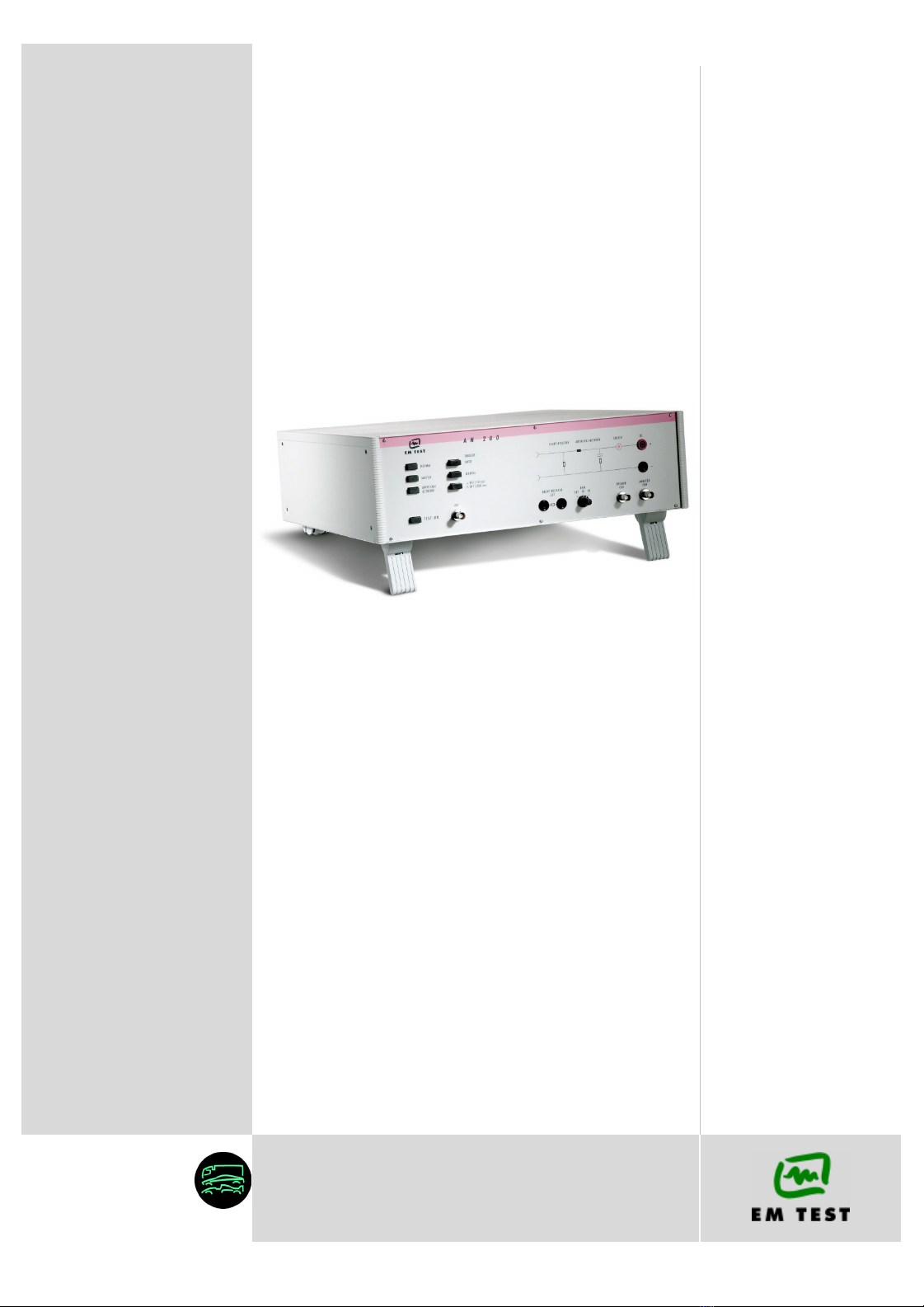
¾AN 200
¾AN 200B
The AN 200 is used to evaluate automotive electrical and
electronic components for conducted emissions of transients
along battery fed or switched supply lines of a Device Under
Test (DUT). A device under test which is considered a potential
source of conducted disturbances should be tested according to
ISO 7637 part 2.
The AN 200 includes an electronic switch for repeatable
switching of inductive loads as well as an artificial network as
specified in ISO.
•ISO 7637 Part 2
Version: 2.00 / 21.11.2003
emc test equipment Replaces: 1.00 / 24.11. 1997
Filename: AN200x operating manual V200.doc
Printdate: 21.11.03

EM TEST AN 200
Bedienungsanleitung V 2.00 2 / 16
Contens
1. Standards covered by AN 200......................................................................................................................3
1.1. Family Series AN 200 ...........................................................................................................................3
2. Operating Functions .....................................................................................................................................4
2.1. Front view..............................................................................................................................................4
2.2. Rear view ..............................................................................................................................................6
3. Equipment description .................................................................................................................................7
3.1. Switch Normal, Switch and Artifical Network ........................................................................................7
3.2. Electronic switch ...................................................................................................................................8
3.3. Ersatzwiderstand...................................................................................................................................8
3.4. Artificial network ....................................................................................................................................9
4. Technical Data .............................................................................................................................................10
5. Calibration / Measuring procedure............................................................................................................11
5.1. Test load .............................................................................................................................................11
5.2. Test voltage.........................................................................................................................................11
5.3. Switch-off times...................................................................................................................................11
5.4. Blockdiagram ......................................................................................................................................11
5.5. Measuring results................................................................................................................................12
5.5.1. Voltage drop in dependence of the test load ......................................................................................12
5.5.2. Measuring results with calibration according to standards .................................................................12
6. Maintenance.................................................................................................................................................13
6.1. General................................................................................................................................................13
6.2. Function check ....................................................................................................................................13
6.3. Test setup ...........................................................................................................................................13
6.4. Safety aspects.....................................................................................................................................13
7. Delivery Groups...........................................................................................................................................14
7.1. Basic equipment..................................................................................................................................14
7.2. Options ................................................................................................................................................14
8. Appendix ......................................................................................................................................................15
8.1. Declaration of CE-Conformity .............................................................................................................15
8.2. AN 200 - Overview ..............................................................................................................................16

EM TEST AN 200
Bedienungsanleitung V 2.00 3 / 16
1. Standards covered by AN 200
With the AN 200 the user covers the following standards for conducted emission transients:
- ISO 7637 Teil 2 Road vehicles; Electrical disturbances by conduction and
cpouling ;
Part 2 : Electrical transients conduction along supply lines
only
- several standards In accordance with ISO 7637 Teil 2
1.1. Family Series AN 200
This manual is written for the following devices:
AN 200 30V 35A
AN 200 B 60V 50A

EM TEST AN 200
Bedienungsanleitung V 2.00 4 / 16
2. Operating Functions
2.1. Front view
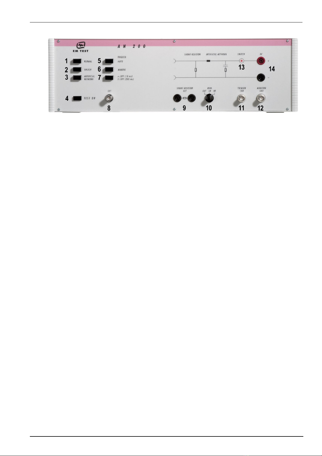
Figure 1 : AN200 front side
1NORMAL operation
2Switch operation
3Artificial network operation
4TEST ON
5AUTO Trigger
6MANUAL Trigger
7Selection of time off
8External Trigger
9Connection external shunt resistor
10 Selection of shunt resistor
11 CRO Trigger (output)
12 CRO measuring output (1:100)
13 LED indication switch-on
14 Connection DUT
1 Normal operation
By pressing the „NORMAL“ button the electronic battery supply switch and the artificial network are both in
operation. Pushing the TEST ON button will start the procedure.
2 Switch operation
By pressing the „SWITCH“ button the electronic battery supply switch is put into operation. Pushing the
TEST ON button will start the switching operations. The artificial network is not used in this mode of
operation. (the switch may be used together with the LD 200 for generaze Field Decay pulses; read details
in the LD 200B manual)
3 Artificial network operation
By pressing the „ARTIFICIAL NETWORK“ button the artificial network is put into operation. The electronic
battery supply switch is short-circuited. The AN 200 can be used as an artificial network only.
4 TEST ON
By pushing the TEST ON button the electronic battery supply switch is put into operation. The switch starts
working with the preselected triggering parameters.
5 AUTO Trigger
By pushing the „AUTO“ button the switching procedures (battery supply OFF – ON) are released in
automatically with a repetition rate of 1Hz. To start the test or measuring procedure the Test On button must
be pushed in.
6 MANUAL Trigger
In Manual Trigger operation (AUTO button must not be pushed in) a single switching event, OFF – ON. To
start the test or measuring procedure the Test On button must be pushed in.
7 Selection of the OFF-time
The operator can select the OFF-time by pushing the button 200ms / 10ms" into the related position. The
user can select between 200ms and 10ms.
8 External Trigger
In Manual Trigger operation (AUTO button must not be pushed in) a single switching event, OFF-ON can be
released by remote control. The external trigger input at the BNC connector EXT must be connected to
ground (short-circuit) to release one single event.
EM TEST AN 200
Bedienungsanleitung V 2.00 5 / 16
Figure 1 : AN200 front side
1NORMAL operation
2Switch operation
3Artificial network operation
4TEST ON
5AUTO Trigger
6MANUAL Trigger
7Selection of time off
8External Trigger
9Connection external shunt resistor
10 Selection of shunt resistor
11 CRO Trigger (output)
12 CRO measuring output (1:100)
13 LED indication switch-on
14 Connection DUT
9 Connections of external shunt resistors
An external shunt resistor of R = 2.5Ω/ 400W (at U = 30VDC) may be connected to the related safety
banana sockets. Together with the existing incorporated resistors it results a total resistor value of 2Ω. The
2Ωvalue is required when measuring transient emissions as per ISO/DIN 7637 standard.
10 Selection of the shunt resistor
With this knob the shunt resistor can be switched to 40Ω, 10Ωor to an external resistor (see point 9.)
11 CRO Trigger
During the switching-off ramp a trigger signal (+ 15V) is generated and is available at the CRO Tigger
output.
12 CRO measuring output
The measured transient emission signal is available at the Monitor output. The AN 200 includes a resistive
divider with a divider ratio of 1:100 and an accuracy of ±2% .
13 LED display indication of Switch-On status
The LED indicates the On-status of the electronic battery supply switch. In this case the DUT is connected to
battery supply.
14 Connection for device under test (DUT)
The DUT is connected at the safety banana output sockets.

EM TEST AN 200
Bedienungsanleitung V 2.00 6 / 16
2.2. Rear view
Figure 2 : AN 200 rear side
1Ventilation grid
2Reference earth connection
3Input DUT supply
4Measuring output BNC plug
5Power On switch
1 Ventilation
This guarantees cooling of the battery supply switch. Ventilation grid and ventilator (blower) must be kept
away from other devices in order to allow sufficient air flow through the battery supply switch.
2 Reference earth connection
This plug is for connecting the AN 200 to the ground reference plane.
3 DUT supply
The battery supply (+) & (-) for the DUT is connected to this input. The nominal dc supply parameters
allowed are 30V / 25A .
4 Measuring output with 50 Ωcoaxial resistor
For measuring conducted emission spectrum on battery supply lines as per ISO/DIN 7637 and
DIN/VDE 0879 an artificial network, as illustrated in chapter 3.3, is compulsory. For this the required the 50Ω
resistor Rz is coaxial and located on the BNC plug.
For measuring the interference spectrum a test receiver or spectrum analyzer with 50Ωinput impedance is
used. The instrument is connected to this BNC socket and the 50Ωcoaxial resistor is replaced by the 50Ω
input impedance of the measuring device.
5 Power on switch
The switch is part of the mains filter. Mains fuses are part of the filter.
230V / 1A and 115V / 2A
EM TEST AN 200
Bedienungsanleitung V 2.00 7 / 16
3. Equipment description
The battery supply switch AN 200 is generally divided into three main parts:
- Electronic switch;
- Shunt resistor RS;
- Artificial network.
ARTIFICIAL
NETWORK
RS SHUNT
RESISTOR
CONTROL
ELECTRONIC
DISCONNECTING
SWITCH
Bild 3: Blockschaltbild
CRO
OUT +
OUT -
IN +
IN -
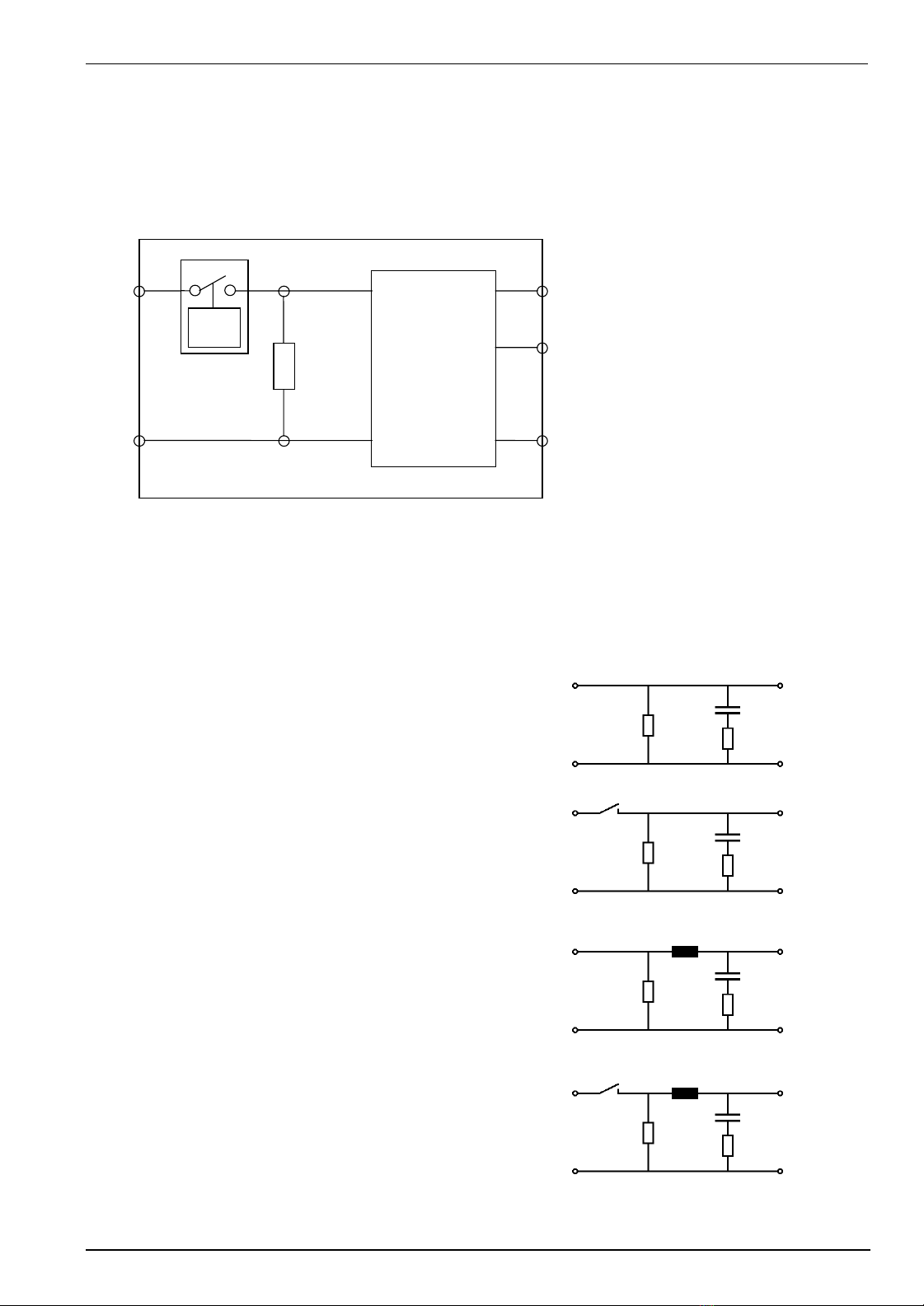
3.1. Switch Normal, Switch and Artifical Network
Depend of the switching position the AN 200 offers different networks. By switching of one of the switches will
release automatically the others. They will go into normal position.
Normal
The internal switch and the inductance are bypassed inthe AN
200. Only the RC network and the shunt resistor are in the circuit.
For remove the RC network you must disconnect the 50Ω
Resistor Rz at the rear side of the AN 200.
Figure 4
Switch
The switch inside the AN 200 is active and the inductance is
bypassed. The switch will open according the setting:
AUTO : 1Hz repetition
MANUAL : Manual release or with ext. Trigger
Interruption : 10ms or 200ms depends on switch position. Figure 5
Artifical Network
In the AN 200 the artifical network is active. The switch is
bypassed. Please check that the 50ΩResistor Rz at the rear side
of the AN 200 is mounted. Otherwise the Artifical network does
not confirm with the standard ISO 7637 part 2
The shunt resistor is switchable between 10Ωand 40Ω.
umschaltbar. Figure 6
Switch and Artifical Network
This mode is not official. The user get this network, when the
switches Switch and Artifical Network are pressed at the same
time.
Figure 7

EM TEST AN 200
Bedienungsanleitung V 2.00 8 / 16
3.2. Electronic switch
The electronic switch disconnects the DUT from battery supply voltage for a specified time in a well specified and
reproducible manner.
The electronic switch is in On status during NORMAL and SWITCH operation while TEST ON is pushed in.. The
red LED indicates On status.
In AUTO mode the electronic switch is triggered internally with 1Hz repetition rate. In MANUAL mode the switch
is triggered either by pushing the MANUAL button or by remote trigger.
The electronic switch can switch currents up to 25A and is able to withstand voltages up to 1000V.
The electronic switch are electronically protected against overload and can withstand short-circuit conditions.
Specific protection requirements of the EUT must be separately assured by the user.
Inrush currents
Inrush currents up to 500A are permitted.
Overvoltage
The switch is protected against over voltages higher than 1000V by internal varistors.
3.3. Shunt resistor
The shunt resistor shall simulate the dc impedance of other connected consumers in the cable tree.
According to ISO/DIN 7637 when measuring transient overvoltage a shunt resistor of 40Ωis required, whereas
when measuring transient overcurrent a shunt resistor of 2Ωis required. For this purpose an external resistor of
2.5 Ω/ 400 W (at 30 V DC) is connected to the safety banana plugs. The external shunt resistor shall be a non-
inductive one.
EM TEST AN 200
Bedienungsanleitung V 2.00 9 / 16
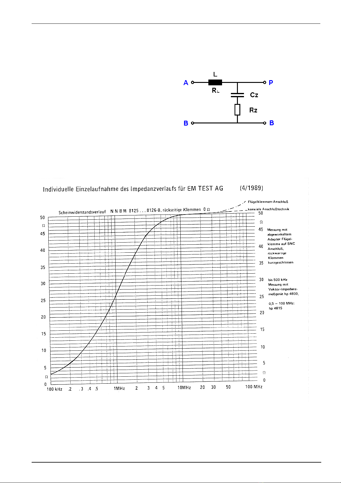
3.4. Artificial network
The artificial network is used to carry out the measurements of conducted emission under constant impedance
parameters. According to ISO/DIN 7637 the following substitute diagram is provided.
Parameter of artifical network
Inductance : L = 5µH Rl < 5mΩ
RC Network : Cz = 0.1µF ( 250V ac )
Rz = 50Ω
Source input: Connectors A, B
Output DUT : Connectors P, B Figure 8
The parallel resistor Rz = 50Ωis built as a coaxial resistor and is placed on the BNC connector at the rear panel.
The impedance characteristic is shown within the following diagram.
The enclosed illustration of a measured curve (impedance characteristic) shows typical impedance values in the
frequency range.
Figure 9 : Impedance of the artifical Network

EM TEST AN 200
Bedienungsanleitung V 2.00 10 / 16
4. Technical Data
Test supply AN 200 AN 200B
Voltage range 0-30 VDC 0-60 VDC
Rated current 25 A 50 A
Short circuit protected
max. inrush current > 500 A
Peak voltage capability 1000 V
Overvoltage protection by varistors
Electronic switch
Switching time (test load L=7 µH / R=0.6 Ω)300 - 400 ns
Switch-off time can be selected 10 ms / 200 ms
Artificial network
Impedance according ISO/DIN 7637 5 µH - 50 Ω
Inductance (5 µH / 5 mΩ)
Shunt resistor (Rs)
Internal selectable 40 Ω/ 10 Ω
Option:
External shunt resistor (Rs = 2 Ω)2 Ω
Trigger
MANUAL Manual trigger of a single event
AUTO Automatic trigger with 1Hz
EXT External trigger 0V, BNC
Mode
NORMAL Switch and artificial network are activated
SWITCH Only the switch is activated
ARTIFICIAL NETWORK Only the network is activated
Measurement
Trigger output for CRO BNC, positive edge + 15 V
Measuring probe included BNC, 1 : 100 ±2%
Switch-on indication LED-display
Dimensions (L x B x H) AN 200 AN 200B
425 x 530 x 180 mm 425 x 530 x 360 mm
19“ 3HE 19“ 6HE
Weight 10 Kg 28 kg
EM TEST AN 200
Bedienungsanleitung V 2.00 11 / 16
5. Calibration / Measuring procedure
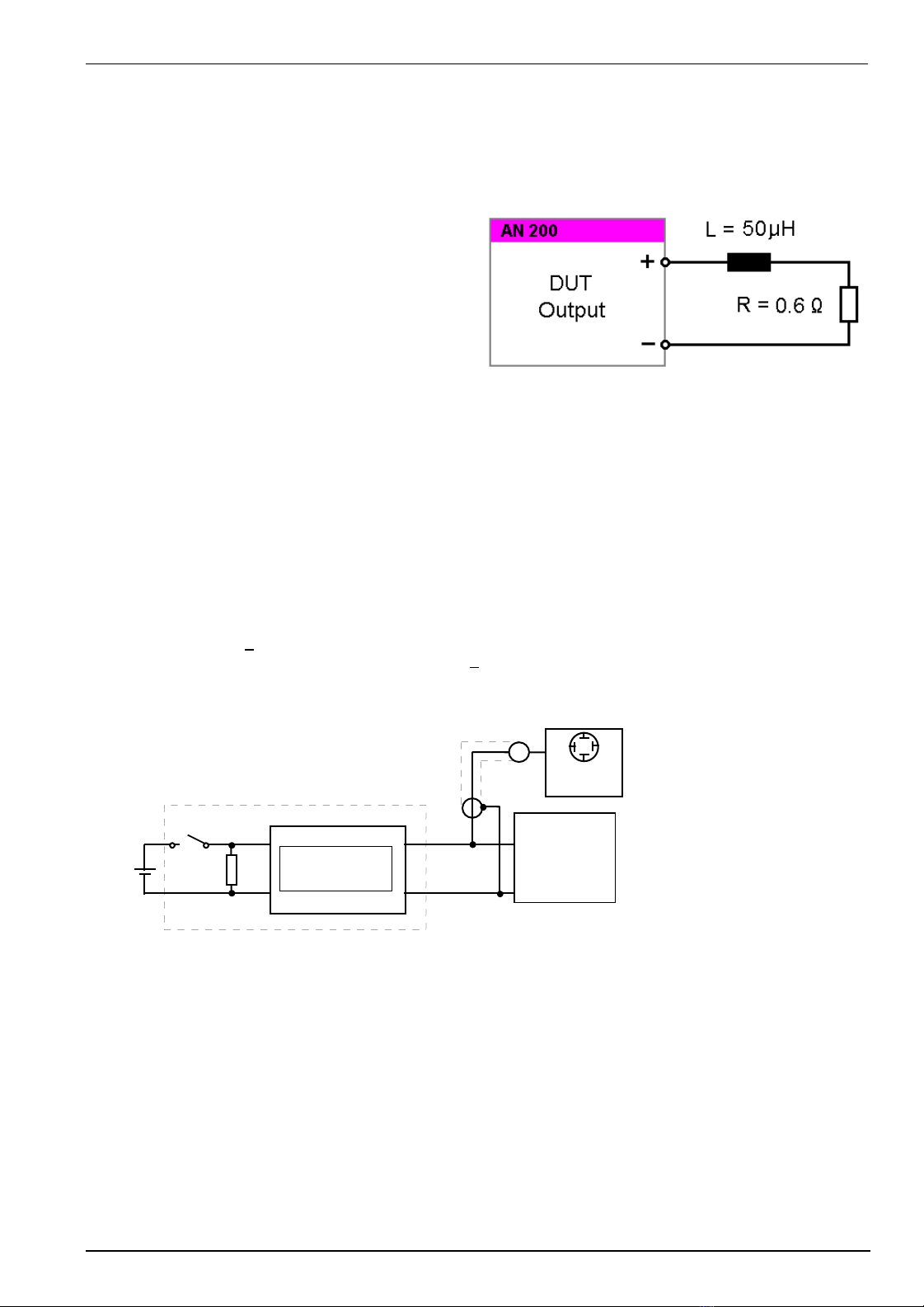
5.1. Test load
For measuring the switch-off time the following test load (DUT) is specified in relevant standard references:
Test load => R (total) = 0,6 Ωin series with
L (total) = 50 µH (1 kHz)
Both R and L also include the variations of the cable and
the structure. The parallel capacity which cannot be
avoided is approx. 50pF. The test must be constructed
such that the permanent current can be used at
maximum test voltage.
Figure 10 : Testlast
5.2. Test voltage
According to the standards the switch-off times should be determined under varying test voltages.
Proposals: for Va : U1 = 13.5V and U2 = 27V
Consequently constant currents of 22.5A or 45A must be considered. Due to the fact that the AN 200 is only
constructed for currents up to 25 A, calibration is only carried out with U1 = 13.5V. The resulting energy consumption
at the test load is approx. 300W.
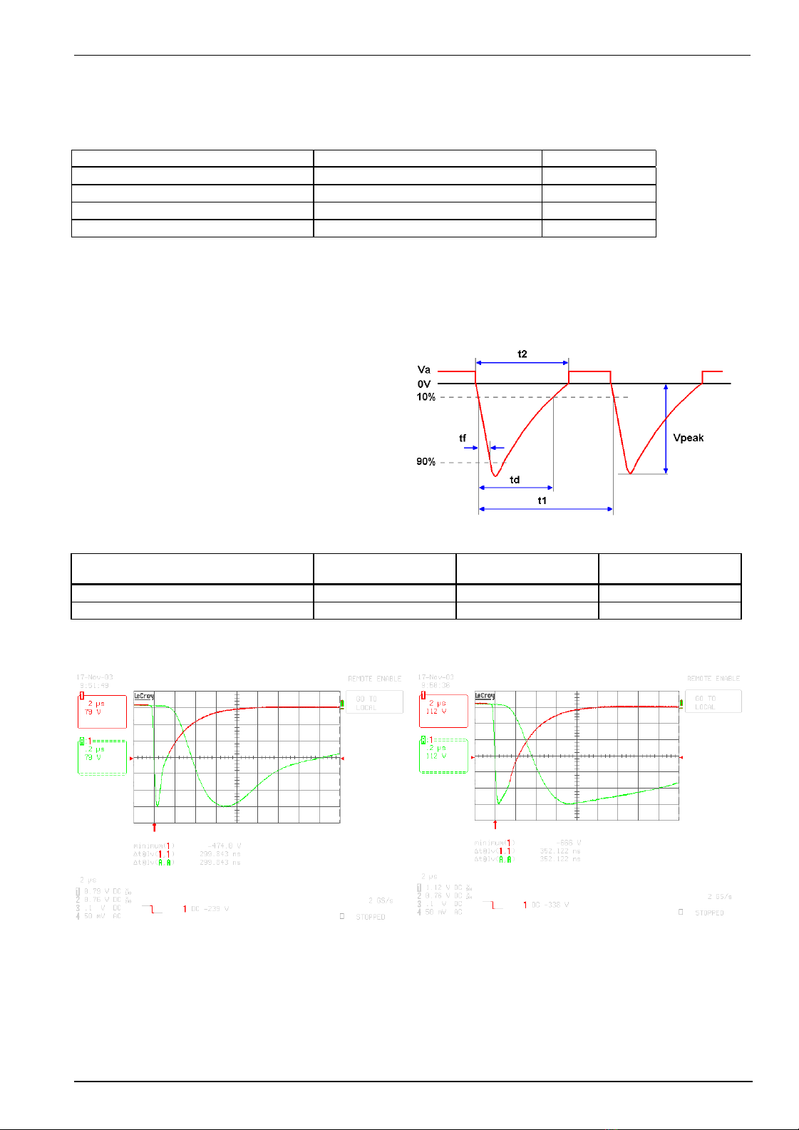
5.3. Switch-off times
The switch-off times are specified as follows, whereas fall time of the switch-off pulse is involved and measured
between 10 and 90% of the maximum amplitude:
ISO 7637 (old version < 1992) tf = 200 ..... 400ns
ISO 7637 new and DIN 40839 part 1 tf = 300ns + 20%
5.4. Blockdiagram
Rs
Source
AN 200
xx
xx
artificial
network
xx cable length 0,5 m
EUT or
standard
load for
calibration
Figure 11 : Blockdiagram test setup
EM TEST AN 200
Bedienungsanleitung V 2.00 12 / 16
5.5. Measuring results
5.5.1. Voltage drop in dependence of the test load
DUT current voltage drop ( reference value ) Tolerance
1A 1.8 V ±30%
10 A 3.0 V ±30%
23 A 3.5 V ±30%
45 A (only AN200B 60V50A) 4.5 V ±30%
Îmanufacturer values
5.5.2. Measuring results with calibration according to standards
All measuring values indicated as well as the curve illustrated have been recorded with a serial model.
Reference values measured with AN 200
Input Voltage: 17.75 V
Output Voltage: 13.50 V
Upeak: - 401 V
tf (90% - 10%): 323 ns
Figure 12 : Pulse parameters
Impedance setting 40ΩVa
output voltage
Vpeak tf 90% - 10%
fall time
Mit Normlast -13.5V ±10% 400V ±30% 300ns ±20%
Mit Normlast ( nur AN200B 60V50A)-27V ±10% 600V ±30% 300ns ±20%
Example for the switch off impulse
Figure 13 : Test load at 13.5V Figure 14 : Test load at 13.5V 27V ( AN 200B )
EM TEST AN 200
Bedienungsanleitung V 2.00 13 / 16
6. Maintenance
6.1. General
The internal switch is absolutely maintenance-free by using a solid state semiconductor .
6.2. Function check
Similar to all measuring and test instruments the correct function of the battery supply switch should be checked from
time to time. The check is best carried out according to the following procedure:
- Switch on the power mains supply and connect the DUT battery supply.
- Select NORMAL operation;
- Select the Off time to 200ms;
- Select the shunt resistor to 10Ω;
- Select the AUTO trigger mode.
After pushing the TEST ON button the LED should now blink at a frequency of 1Hz and the EUT supply is switched
off for 200ms each time. This can be checked at the Monitor CRO output. For this purpose a storage oscilloscope of
at least 20MHz bandwidth is needed.
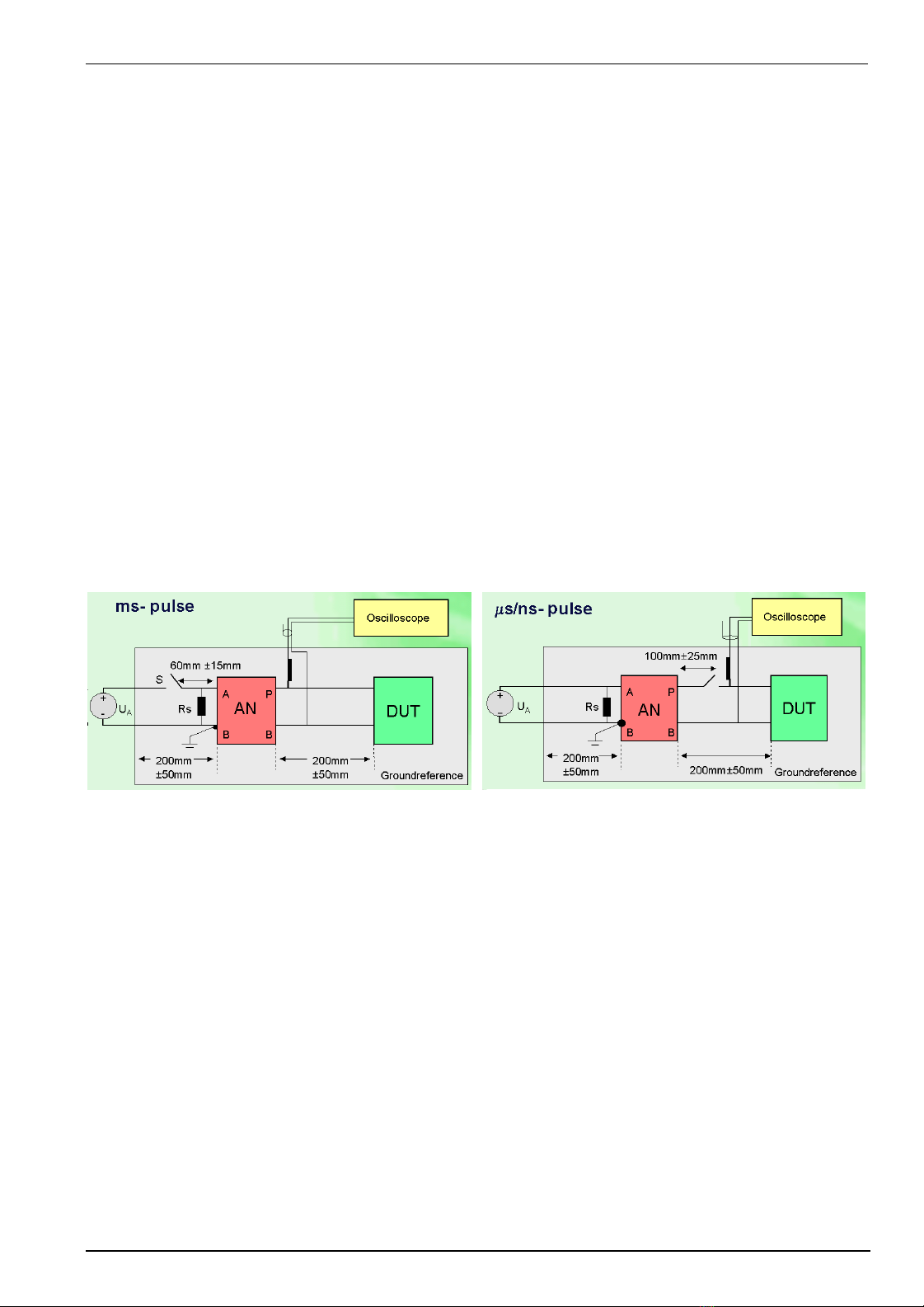
6.3. Test setup
The test offered by the AN 200 generator is a immunity test on electronic equipments or devices. Therefore it is
the responsibility of the user to avoid critical failures and risks to the environment and operator.
Please refer to the safety manual before starting to work with the AN 200
Figure 15 : Setup for pulses in the ms range Figure 16 : Setup for pulses in the µs / ns range
Important
- The artificial network AN shall be connected directly to the ground
reference plane.
- All wires between AN and the DUT shall be isolated from the
ground plane by 50mm.
- The DUT will be placed on the ground plane as in real installation.
- directly grounded to the ground plane or
- 50mm isolated from the ground plane
- The position of the instruments shall be as specified in the standard.
6.4. Safety aspects
National and international recommendations regarding human safety must be followed. When setting up the test
national and international regulations regarding human safety have to be guaranteed.
The test offered by the AN 200 generator is a immunity test on electronic equipments or devices. Therefore it is
the responsibility of the user to avoid critical failures and risks to the environment and operator.
Long and distributed lines of the EUT are able to radiate a certain energy to their vicinity. Therefore it is also the
responsibility of the user to decide whether it is allowed to conduct immunity tests in a given installation.

EM TEST AN 200
Bedienungsanleitung V 2.00 14 / 16
7. Delivery Groups
7.1. Basic equipment
•Artifical network AN 200 / AN 200B
•Mains cable
•1 set safety labor cables red / black
•Manual on CD
•Calibration certificate
7.2. Options
•AN 200B Artifical network for 60V 50A
Figure 17 : AN 200B front view Figure 18 : AN 200B rear view

EM TEST AN 200
Bedienungsanleitung V 2.00 15 / 16
8. Appendix
8.1. Declaration of CE-Conformity
Manufacturer : EM TEST AG
Address: Sternenhofstr. 15CH 4153 Reinach
Switzerland
declares, that under is sole responsibility, the product’s listed below, including all their options, are conformity with the
applicable CE directives listed below using the relevant section of the following EC standards and other normative
documents.
Product‘s name: Artifical Network
Model Number(s) AN 200, AN 200B
Low Voltage Directive 73/23/EEC
Standard to which conformity is declared:
EN 61010-1:1993 Safety
EMC Directive 89/336/EEC
Standard(s) to which conformity is declared:
Emissions:
EN 61000-6-4 2001
EN 55022:1998 +A1:2000, Class A
EN 61000-3-2 A14: 2000
Conducted and radiated.
Harmonics
Immunity: EN 61000-6-2 2001 EN 61000-4-2:1995 +A1:1998 +A2:2001 Electrostatic Discharges
EN 61000-4-3:2002 +A1:2001 RF Electromagnetic Field
EN 61000-4-6:1996 + A1:2001 Conducted RF
EN 61000-4-4: 1995+A1:2001 +A2:2001 Electrical Fast Transient / Burst
EN 61000-4-5: 1995+A1:2001 Surge
EN 61000-4-11: 1994+A1:2000 DIPS & Voltage Variations
European representative Manufacturer
EM TEST GmbH EM TEST AG
Lünenerstr. 211 Sternenhofstr. 15
D 59174 Kamen CH 4153 Reinach
Tel: 00492307-18042 Tel: 004161-7179191
Fax: 00492307-17050 Fax: 004161-7179199
By U. Flor
General manager
H. Kunkel
Design and Research
Place Kamen, Germany Reinach BL , Switzerland
Date 20. November 2002 20. November 2002
EM TEST AN 200
Bedienungsanleitung V 2.00 16 / 16
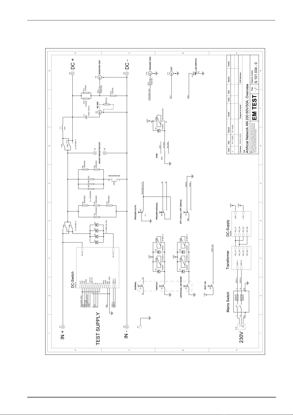
8.2. AN 200 - Overview
Figure 19 : Overview AN 200 / AN 200B
This manual suits for next models
2
Table of contents
Other EMTEST Test Equipment manuals

EMTEST
EMTEST dito User manual

EMTEST
EMTEST CNI 503 Series Technical Document

EMTEST
EMTEST CWS 500A / 75 User manual

EMTEST
EMTEST CNI 508 N2 User manual

EMTEST
EMTEST PFS 200N Series Instruction Manual

EMTEST
EMTEST PFM 200N200 User manual

EMTEST
EMTEST variac-NX 1-260-16 User manual

EMTEST
EMTEST PFM 200N100.1 User manual

EMTEST
EMTEST VDS 200Q10 Series User manual

EMTEST
EMTEST esd NX30 User manual


