EMTEST VDS 200Q10 Series User manual
M a n u a l
f o r O p e r a t i o n
VDS 200Q10 series
Voltage Drop Simulator pulses 2b, 4
➢VDS 200Q10, VDS200Q10.1
Testing of electronic modules in 12V/24V or 42V supply
systems.
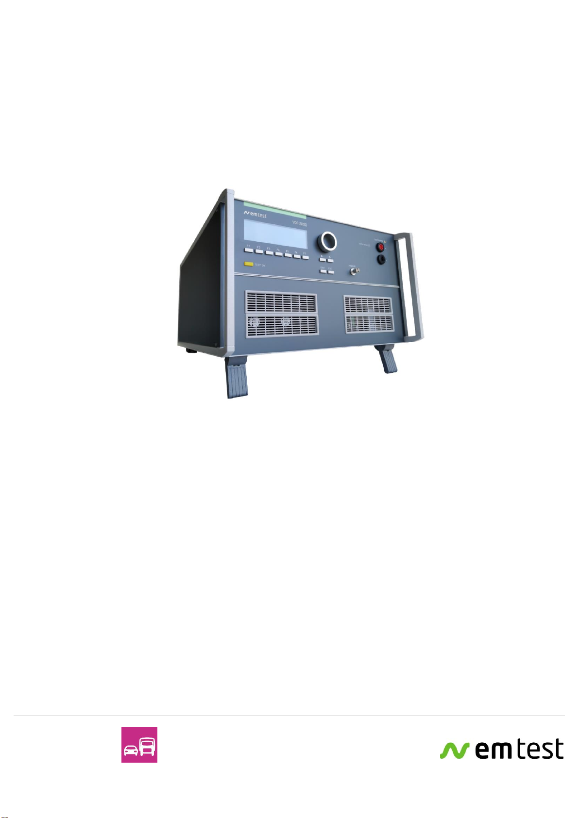
The VDS 200Q10 series is four-quadrant linear power amplifier
with a very low source impedance. It simulates the battery
power supply of a vehicle and complex power supply distortions
in the power range up to 600W. Many different waveforms are
integrated as standard such as pulse 2b required by ISO 7637
and the starting profile from ISO 16750 as well as requirements
from many manufacturers’ standards like LV 124.
•ISO 7637
•ISO 16750
•SAE J1113
•Manufacturer spec
LV 124, LV 148, GM,
Ford, Chrysler, BMW,
VW, PSA, Renault,
Fiat ....
Version:
1.00 / 13.04.2021
the benchmark for emc
Replaces:
-
File Name:
UserManual-VDS200Q10.x-E-V1.00
Print Date:
13.4.2021


AMETEK CTS VDS 200Q10 Series
Manual for Operation V 1.00 3 / 35
Contents
1. Model Overview .............................................................................................................................................4
1.1. VDS 200Q10 series models .........................................................................................................................4
1.2. Construction..................................................................................................................................................4
2. Operating Functions .....................................................................................................................................5
2.1. Front view VDS 200Q10.x ............................................................................................................................5
2.2. Rear view VDS 200Q10.x.............................................................................................................................6
2.3. Safety with voltage setting............................................................................................................................8
3. Operation......................................................................................................................................................10
3.1. Description of the menus............................................................................................................................10
3.2. Main Menu ..................................................................................................................................................10
3.2.1. Change of parameters................................................................................................................................11
3.3. Wave Simulator...........................................................................................................................................12
3.3.1. ISO 7637.....................................................................................................................................................13
3.3.1.1. Pulse 4 voltage drop..................................................................................................................................13
3.3.1.2. Pulse 2b......................................................................................................................................................13
3.3.2. ISO 16750-2 WD 03/2000-2.......................................................................................................................14
3.3.2.1. Short voltage drop.......................................................................................................................................14
3.3.2.2. Slow decrease / increase............................................................................................................................14
3.3.2.3. Supply voltage profile..................................................................................................................................15
3.3.2.4. Pulse ’Starting profile’ .................................................................................................................................15
3.3.2.5. Sinus Sweep...............................................................................................................................................16
3.3.2.6. Overvoltage Vmax ......................................................................................................................................16
3.3.3. Functions ....................................................................................................................................................17
3.3.3.1. Sine wave ...................................................................................................................................................17
3.3.3.2. Jump Start...................................................................................................................................................18
3.3.3.3. VDS Externally via the analog input ...........................................................................................................18
3.3.3.4. Pulse 4 ( GM 9105 P) .................................................................................................................................19
3.3.3.5. DC source...................................................................................................................................................20
3.4. Service........................................................................................................................................................21
3.5. Setup...........................................................................................................................................................22
3.6.Source Settings...........................................................................................................................................23
4. Technical Data.............................................................................................................................................27
4.1. Test level.....................................................................................................................................................27
4.2. Trigger.........................................................................................................................................................27
4.3. Input/output.................................................................................................................................................27
4.4. Interfaces ....................................................................................................................................................27
4.5. General .......................................................................................................................................................28
4.6. Environmental conditions............................................................................................................................28
5. Maintenance.................................................................................................................................................29
5.1. General .......................................................................................................................................................29
5.2. Test set-up..................................................................................................................................................29
5.3. Test set-up with software iso.control ..........................................................................................................29
5.4. Example Test setup with VDS 200Q10.x, AutoWave and PFM 200N100 .................................................30
5.5. Example Test setup with AutoWave and VDS 200Q10.x...........................................................................31
5.6. Calibration and Verification.........................................................................................................................32
5.6.1. Factory calibration.......................................................................................................................................32
5.6.2. Guideline to determine the calibration period of AMETEK CTS instrumentation.......................................32
5.6.3. Calibration of Accessories made by passive components only:.................................................................32
5.6.4. Periodic In-house verification......................................................................................................................32
6. Delivery Groups...........................................................................................................................................33
6.1. Basic equipment VDS 200Q10.x ................................................................................................................33
6.2. Accessories and options.............................................................................................................................33
6.3. Connectors..................................................................................................................................................33
7. Appendix ......................................................................................................................................................34
7.1. Declaration of CE-Conformity.....................................................................................................................34
7.1.1. Declaration of CE-Conformity VDS 200Q10...............................................................................................34
7.1.2. Declaration of CE-Conformity VDS 200Q10.1............................................................................................35

AMETEK CTS VDS 200Q10 Series
Manual for Operation V 1.00 4 / 35
1.
Model Overview
1.1.
VDS 200Q10 series models
Standard models
Model Voltage
voltage
current
inrush current
Sine f max
VDS 200Q10-100
-60 to +60 V
Imax = ±10 A
Not supported
180 kHz
VDS 200Q10-120
-60 to +60 V
Imax = ±10 A
Not supported
180 kHz
VDS 200Q10-230
-60 to +60 V
Imax = ±10 A
Not supported
180 kHz
VDS 200Q10.1-100
-60 to +60 V
Imax = ±10 A
Not supported
180 kHz
VDS 200Q10.1-120
-60 to +60 V
Imax = ±10 A
Not supported
180 kHz
VDS 200Q10.1-230
-60 to +60 V
Imax = ±10 A
Not supported
180 kHz
1.2.
Construction
The Voltage Drop Simulator VDS 200Q10.x is built in a 19" / 6HU housing.
On request the VDS 200Q10.x generator could also be built into a rack.
AMETEK CTS VDS 200Q10 Series
Manual for Operation V 1.00 5 / 35
2.
Operating Functions
2.1.
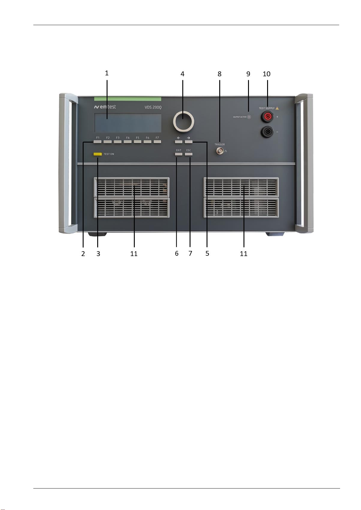
Front view VDS 200Q10.x
1Display
2Function keys "F1..F7"
3"TEST ON"
4Knob (Inc/Dec)
5 Cursor keys "" and "→"
6EXIT
7ESC
8BNC CRO Trigger ( for oscilloscope)
9 LED OUTPUT ACTIVE
10 Test Supply
11 Cooling
1 Display
All functions and parameters are displayed (8 lines with max. 40 characters).
2 Function keys "F1 .. F7"
Parameters and functions, displayed in the lowest line, can be selected with the related function key.
3 Test On
By pressing the key "TEST ON" the test procedure is initiated with the preselected parameters. The yellow
button is illuminated and indicates the Test ON status. After “Test OFF” or when no test is started, the output
voltage and the current will be set to zero.
4 Knob (Inc / Dec)
The knob increments or decrements test parameters with a numeric value or selects from a list of parameters.
5 Cursor keys
Parameters and functions can be changed on-line. The selection of these parameters is realized with the cursor
moving to the left or to the right.
6 Exit
Pressing the "EXIT" function will return to the previous menu. This is only possible if no test routine is running.
7 ESC
When pressing the ESC button the user moves back one page in the menu.
8 BNC CRO Trigger
At the BNC connector CRO TRIGGER a signal is available to trigger an oscilloscope.

AMETEK CTS VDS 200Q10 Series
Manual for Operation V 1.00 6 / 35
9 LED OUTPUT ACTIVE
This LED is on during the power on status.
10 Test Supply
Output to the DUT or other generators.
4mm banana connectors.
11 Cooling
Grid with fans for cooling behind. Ensure nothing blocks the air circulation (distance > 0.5m)
2.2.
Rear view VDS 200Q10.x
1
TEST SUPPLY OUT
8
Mains switch
2
SENSE
9
Mains fuse
3
Reference ground connection
10
Mains input
4
Cooling
11
IEEE 488.1
5
FRAME BUS
12
USB port
6
TRIGGER IN
13
CN interface
7
ANALOG IN
14
FAIL1 / FAIL2
1 TEST SUPPLY OUT
Output to DUT
2 Sense
Sense lines to compensate voltage drop across connection VDS –DUT (max. 4V)
Note: Sense lines are only supported for VDS 200Q10.1 models and higher.
3 Reference ground connection
Massive metal ground point to be connected to a reference ground point in the system during testing.
4 Cooling
Grid with or without fans for cooling behind. Ensure you do not block these grids.
Minimum distance to a wall or other blocking objects >20cm

AMETEK CTS VDS 200Q10 Series
Manual for Operation V 1.00 7 / 35
5 FRAME BUS
EM Test internal communication bus. Daisy chain all equipment connected to the bus, terminate
at the end of the chain.
6 TRIGGER IN
External trigger IN signal
7 ANALOG IN
-10 / +10VDC. Connection to AutoWave or an external arbitrary waveform generator.
8 Mains switch
To power up the equipment
9 Mains fuse
230 Vac, 6.3 A, 5 x 20 mm
115 Vac, 10 A, 5 x 20 mm
100 Vac, 16 A, 5 x 20 mm
10 Mains input
Max. 16A, depending on power mains voltage.
11 IEEE 488 / GPIB
Parallel IEEE 488 interface to remote control the generator with a software tool.
12 USB Port
USB interface “USB B” connector. For data transfer a USB interface is available. The internal RS 232
interface is converted to USB standard. Therefore the user must set the same Baudrate in the device and
control software.
Interface is supported for iso.control, but not for autowave.control (either IEEE or FRAME BUS).
13 CN interface
Interface to other EM TEST devices, currently not used
14 FAIL1 / FAIL2
FAIL 1 can be used for failure detection at the DUT. If the input is set to ground (chassis) the generator
stops and terminate the test. The SW test routine than can be stopped completely continued at the break
point. A message of FAIL 1 is indicated in the LCD display as well as in the ISM software.
FAIL2 can be used for failure detection at the DUT. If the input is set to ground (chassis) the actual test
routine is paused as long as the low level signal is available at the FAIL 2 input. With no longer set to ground
signal the test procedure continues automatically. A message of FAIL 2 is indicated in the LCD display as
well as in the ISO.CONTROL software.

AMETEK CTS VDS 200Q10 Series
Manual for Operation V 1.00 8 / 35
2.3.
Safety with voltage setting
To ensure a safe operation of the DUT (Device Under Test) some restrictions in the operation of the instrument
are built in. These restrictions are explained within this paragraph.
CAUTION:
The VDS 200N and VDS 200Q series, as well as most linear power amplifiers will create spikes at
start and stop. Do not touch any conducted parts of the system and be sure to remove the DUT
during power up and shut down or damage may occur.
Do not use the VDS 200Q10.x with a parallel battery.
A four-quadrant source, like the VDS 200Q10.x can supply both positive and negative voltage as well as positive
or negative current in any combination. It can also sink current that may be supplied from external sources.
Often, using a classic 'source' (power supply or 1 - 2 quadrant source) the user felt the need to buffer the voltage
in order to get inrush or to properly simulate the impedance of the battery in the car. This, of course, can no
longer be controlled as the source simply becomes a charger the the battery.
However, when using a four-quadrant source like the VDS 200Q10.x and the source's voltage is set lower than
the battery, the battery can discharge through the source.
This can result in a dangerous condition, not only for the four-quadrant source, but also because you've
effectively short-circuited the battery when setting the voltage to zero (or switching the four-quadrant source off!).
Remember that all sources must have a source impedance of <10 mOhm according to ISO 7637.
Finally, by shorting (or overcharging) the battery, the battery can actually overheat, crack (releasing acid!) or
even explode due to the release of hydrogen.
CAUTION:
Do not use a parallel battery with the VDS 200Q10.x or a dangerous condition can occur by
exceeding the current of the VDS 200Q10.x, or overheating the battery.
CAUTION:
While the output of the VDS 200Q10.x is floating, the battery negative pole should be within 10V
of earth for safety reasons.
Do not put the simulator in parallel with other sources.
The VDS 200Q10.x basically is divided into 2 different operation modes, which includes their individual test
routines and supply voltage setting. The different modes can be listed as follows:
DC Source (VDS Generator - User Test Routines - DC Source)
Within this mode the VDS 200Q10.x is used as a simple DC power source in the range of up to 60V / 0-10A and
an integrated current limiter.
Arbitrary Wave Simulator
Within this mode the VDS 200Q10.x generates arbitrary waveforms and signals which are specified in different
standards, such as pulse 4 of ISO 7637.
AMETEK CTS VDS 200Q10 Series
Manual for Operation V 1.00 9 / 35
All these different test modes are changing generally the voltage supply setting of the generator in a different
way. This would mean a certain risk for the operator to burn out the connected DUT by higher DC supply
voltages as intended. Therefore it is decided to clearly separate the two test modes by the following structure
listed:
Analogue input +10/-10V
The amplifier can be controlled by an external signal generator. The operator therefore shall select the User
Test Routines of the VDS 200Q10.x part and start the menu Extern. The amplifier is then able to be remotely
controlled.
The input signal range is +10 to -10V in the frequency range of 0-180kHz. The output power (EUT test
supply) is capable of +60V / -60V and a nominal current depending on setting. For example, a 2V input
signal would result in 14V output.
1. DC source
When entering the Arbitrary Wave test mode the dc output voltage of the VDS 200Q10.x is automatically set to
the nominal voltage of the DUT. The actual nominal voltage can be defined in the service menu under "Set-up".
When starting the related test routines the output voltage will be generated as per the setting shown up in the
display for each individual test routine.
- The operator can accept this setting and start the test immediately.
- The operator can first change the parameters and than start the test.
When leaving the test mode DC source the output voltage is automatically reset to the nominal supply voltage of
the DUT. The previous voltage setting will be stored in the test file.
2. Arbitrary Wave Simulator
When selecting the Arbitrary Wave mode, the output voltage will be set automatically to the nominal voltage of
the DUT. The actual nominal voltage can be defined in the service menu under "Set-up".
When starting the related test routines, the output voltage will be generated as per the setting shown up in the
display for each individual test routine.
- The operator can accept this setting and start the test immediately.
- The operator can first change the parameters and then start the test.
When leaving the test mode Arbitrary Wave Simulator, the output voltage is automatically reset to 0V. The
previous voltage test parameters will be stored and can be used for the next test.
The consequence of the structure is that between the different test modes
the DUT supply is automatically switched off.
Be sure to select the appropriate bandwidth (Capacitive, Standard, High Freq.) in the Service
menu appropriate for the necessary test frequency.
While the full voltage and frequency can be programmed, bandwidth is typically measured at
the -3dB point. Therefore, please keep in mind that there will be some attenuation at the
maximum frequencies of each range that may have to be compensated for.

AMETEK CTS VDS 200Q10 Series
Manual for Operation V 1.00 10 / 35
3.
Operation
3.1.
Description of the menus
The simulator VDS 200Q10.x is operated by an easy menu control system.
Seven function keys are available to select parameters and functions. All
functions are indicated on the display; max. 8 lines and 40 characters.
The selected parameter is blinking and can be changed by turning the knob (incr./decr.).
➔ : The digit to be changed can be selected with the cursor (➔ ).
- Set values are directly indicated on the screen.
- Status on the bottom lines shows the desired status after pressing the function key.
ESC : ESC will take you back to the previous level in the menu and set the displayed
values. The latest settings are stored automatically and will be recalled when the
menu is selected again.
EXIT : The firmware will reset to the main screen.
AMETEK CTS
V D S 2 0 0 Q10.1
Voltage Drop Simulator
V 1.00.00
Int. V1.00.00
Waveforms
SWN: 001234
The serial number and the version number SWN are
used for traceability reasons. These numbers are listed
in the factory test reports and calibration certificates.
These numbers also are listed within the test reports
generated by the iso.control software
Start-up display example VDS 200Q10.1
3.2.
Main Menu
MAIN MENU
F1 : Wave Simulator
F7 : Service
F1
F2
F3
F4
F5
F6
F7
F1 Wave Simulator
In this mode, the internal signal generator is used to generate arbitrary waveforms as required in different
standards.
The operator can use the generator in this mode as a,
- DC power supply source,
- powerful power arbitrary wave generator with integrated test routines
- or simply as a battery simulator
The amplifier can be remote controlled by any external arbitrary generator. External generators shall be
connected at the rear part of the equipment. Any waveform can be generated up to the upper bandwidth of the
unit.
F7 Service
Set-up, self-test, source settings and addresses of AMETEK CTS can be selected and displayed.

AMETEK CTS VDS 200Q10 Series
Manual for Operation V 1.00 11 / 35
3.2.1.
Change of parameters
Easy and very fast operation of all standard functions of the equipment. The latest simulator settings are stored
automatically and will be recalled when Quick Start is next selected.
Page 5 (Show parameters)
ISO Pulse 4
Vb = 12.0V Va1 = -7.0V
Va2 = -3.0V t1 = 0.2s
t6 = 5ms t7 = 5ms
t8 = 5ms tf = 5ms
Va = 13.5V tri = Auto
I = 5A
Start Change
F1
F2
F3
F4
F5
F6
F7
Press START and the test routines begin to work.
Press CHANGE and the actual parameter can be changed.
Page 6 (Change of page 1/2) Page 6 (Change of page 2/2)
ISO Pulse 4
ISO Pulse 4
Vb: 0.0V - 60.0V
t8: 0.1 s - 99.9 s
Vb Va1 Va2 t1 t6 t7
t8 tf Va tri I
12.0 -7.0 -3.0 0.2 5 5 1/2
13.5 5 13.5 Auto 5 2/2
F1
F2
F3
F4
F5
F6
F7
F1
F2
F3
F4
F5
F6
F7
The user can select the parameter to be changed with the related function key and change the value by turning
the knob. The cursor allows the user to define the value of the digit to be changed (fast or slow change).
Pressing of the ESC button will bring the user back to the previous level from where the test can be
restarted with new parameters.
Page 6 (Start)
ISO Pulse 4
After start the actual voltage and current measurements
are displayed. All function keys except F2 (Man) within
the manual trigger mode can stop the test routine. The
latest setting will be displayed.
Pressing the key F3 while the test is running, the
display change to the ZOOM mode and is indicating the
actual voltage and current measurement in big letters.
Vb = 12.0V Va1 = -7.0V
Va2 = -3.0V t1 = 0.2s
t6 = 5ms t7 = 5ms
t8 = 5ms tf = 5ms
Va = 13.5V tri = Auto
I = 5A I = 3.5 A
Stop Zoom V = 7.0 V
F1
F2
F3
F4
F5
F6
F7
Page 6 (Stop)
ISO Pulse 4
By pressing any function key the Start, Change or
Continue mode will come up in the display. F3 will
continue the same test routine. Also the test time will
continue running. If the user first selects Start or
Change, the test will be stopped completely.
Vb = 12.0V Va1 = -7.0V
Va2 = -3.0V t1 = 0.2s
t6 = 5ms t7 = 5ms
t8 = 5ms tf = 5ms
Va = 13.5V tri = Auto
I = 5A I = 3.5 A
Stop Zoom V = 7.0 V
F1
F2
F3
F4
F5
F6
F7
Start Change Cont.
F1
F2
F3
F4
F5
F6
F7

AMETEK CTS VDS 200Q10 Series
Manual for Operation V 1.00 12 / 35
3.3.
Wave Simulator
Page 2
Waveform Simulator
F1 : Standards
F2 : Functions
F3 : DC Power Supply
F1
F2
F3
F4
F5
F6
F7
Page 3
STANDARDS
F1 : ISO 7637
F2 : ISO 16750-2 or WD 03/2000-2
F1
F2
F3
F4
F5
F6
F7
Pages 4
ISO 7637
ISO 16750-2 WD 03/2000-2
F1: Pulse 4
F1: Short voltage drop
F2: Pulse 2b
F2: Slow decrease / increase
F3: Supply voltage profile
F4: Pulse ’Starting profile’
F5: Sweep
F6: Overvoltage Vmax
Page 3
FUNCTIONS
F1 : Sinus
F2 : Jumpstart
F3 : VDS Extern
F4 : Pulse 4 (GM 9105P)
F1
F2
F3
F4
F5
F6
F7

AMETEK CTS VDS 200Q10 Series
Manual for Operation V 1.00 13 / 35
3.3.1.
ISO 7637
3.3.1.1.
Pulse 4 voltage drop
This pulse simulates supply voltage reduction caused by energizing the starter-motor circuits of internal
combustion engines, excluding spikes associated with starting.
tf [Vb-Va1] < 5ms
Input restrictions
0.0 V <= Vb + Va1 <= 60.0V
0.0 V <= Vb + Va2 <= 60.0V)
Parameters:
Vb
0.0V
-
+60.0V
Va1
- 60.0V
-
+ 60.0V
Va2
-60.0V
-
+ 60.0V
t1
0.1s
-
99.9s
t7
5ms
-
999ms
t8
5ms
-
999ms
t9
0.1s
-
99.9s
t11
5ms
-
999ms
Va
0.0V
-
+ 60.0V
I
1A
-
(Imax)
tri
Auto / Manual
3.3.1.2.
Pulse 2b
This pulse simulates transients from DC motors acting as generators after ignition is switched off.
tr, tf ( 10/90%) =1ms 50%
Input restrictions
Va1 0.0V
0.0 V Vb + Va1 60.0V
Parameters:
Vb
0.0V
-
+60.0V
Va1
- 60.0V
-
0.0V
t1
0.1s
-
99.9s
t6
1ms
-
999ms
td
5ms
-
9999ms
int
0.1s
-
99.9s
n
1
-
30,000 / endl.
tri
Auto / Manual
I
1A
-
(Imax)
AMETEK CTS VDS 200Q10 Series
Manual for Operation V 1.00 14 / 35
3.3.2.
ISO 16750-2 WD 03/2000-2
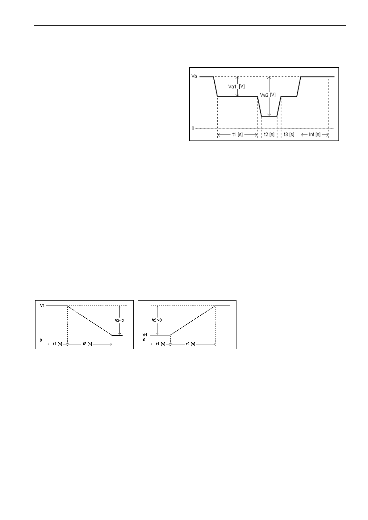
3.3.2.1.
Short voltage drop
This test is to simulate the effect of a classical fuse actuation in another circuit.
tr, tf = 10ms
Input restrictions
0.0 V Vb + Va1 60.0V
0.0 V Vb + Va2 60.0V
Parameters:
Vb
0.0V
-
+60.0V
Va1
- 60.0V
-
+60.0V
Va2
- 60.0V
-
+60.0V
t1
0.1s
-
99.9s
t2
0.1s
-
99.9s
t3
0.1s
-
99.9s
int
0.1s
-
99.9s
n
1
-
30,000 / endl.
tri
Auto / Manual
I
1A
-
(Imax)
3.3.2.2.
Slow decrease / increase
This test is to simulate a gradual discharge and recharge of the battery.
Parameters:
V1
0.0V
-
+60.0V
V2
- 60.0V
-
+60.0V
t1
0.1s
-
99.9s
t2
0.1s
-
9999.9s
I
1A
-
(Imax)
Remarks:
WD 03/2000-2 Voltage change rate = ( 3 0.1 ) V per minute
ISO 16750-2 Voltage change rate = ( 0.5 0.1 ) V per minute

AMETEK CTS VDS 200Q10 Series
Manual for Operation V 1.00 15 / 35
3.3.2.3.
Supply voltage profile
This test is to determine the reset behavior of the device under Test at different voltage drops. This test is
applicable to equipment with reset function.
Parameters:
Vb
0.0V
-
60.0V
Va1
- 60.0V
-
60.0V
Va2
- 59.9V
-
60.0V
Ve
- 60.0V
-
60.0V
dVa
- 60.0V
-
60.0V
t1
0.1s
-
99.9s
t2
0.1s
-
99.9s
t3
0.1s
-
99.9s
n
1
-
30,000 / endl.
tri
Auto / Manual
I
1A
-
(Imax)
3.3.2.4.
Pulse ’Starting profile’
This test simulates a motor startup including a possible ripple.
tr, tf = 10ms
Ripple = 2Hz
Input restrictions
0.0 V Vb + Va1 60.0V
0.0 V Vb + Va2 60.0V
Parameters:
Vb
0.0V
-
60.0V
Va1
- 60.0V
-
60.0V
Va2
- 60.0V
-
60.0V
t1
0.1s
-
999ms
t7
5ms
-
999ms
t8
5ms
-
999ms
t9
0.5s
-
99.5s
t11
5ms
-
999ms
n
1
-
30,000 / endl.
tri
Auto / Manual
I
1A
-
(Imax)

AMETEK CTS VDS 200Q10 Series
Manual for Operation V 1.00 16 / 35
3.3.2.5.
Sinus Sweep
This test simulates a residual a.c. on the dc supply
During Int f3 is applied.
Limitations
Vb + Vp <= 60.0V
Vb - Vp = 0.0V
Parameters:
Vb
0.0V
-
60.0V
Vp
0.0V
-
0.1 –60V
f1
0.001Hz
-
180.000kHz
f2
0.001Hz
-
180.000kHz
f3
0.001Hz
-
180.000kHz
t1
0.1s
-
999.9s
t2
0.1s
-
999.9s
int
0s
-
999s
n
1
-
30,000 / endl.
tri
Auto / Manual
I
1A
-
(Imax)
3.3.2.6.
Overvoltage Vmax
This test simulates a high energy load dump pulse.
Input restrictions
0.0 V V1 + V2 60.0V
Parameters:
V1
0.0V
-
60.0V
V2
0.0V
-
60.0V
t1
0.01s
-
999.99 s
t2
0.01s
-
999.99 s
t3
0.01s
-
999.99 s
int
0.1s
-
99.9s
n
1
-
30,000 / endl.
tri
Auto / Manual
I
1A
-
(Imax)

AMETEK CTS VDS 200Q10 Series
Manual for Operation V 1.00 17 / 35
3.3.3.
Functions
3.3.3.1.
Sine wave
Limitations
Vb + Vp <= 60.0V
Vb - Vp = 0.0V
Parameters:
Vb
0.0V
-
60.0V
Vp
0.1V
-
60.0V
t1
0.1s
-
99.9s
f1
0.001kHz
-
180.00kHz
f< 100Hz 1.2Hz
t2
1.0s
-
999.9s
n
1
-
30’000 / endl.
I
1.0A
-
(Imax)
Be sure to select the appropriate bandwidth in the Service menu appropriate for the
necessary test frequency.

AMETEK CTS VDS 200Q10 Series
Manual for Operation V 1.00 18 / 35
3.3.3.2.
Jump Start
Limitations
V1 + V2 <= 60.0V)
V1 + V2 = 0.0V
Parameters:
V1
0.0V
-
60.0V
V2
- 60.0V
-
60.0V
t1
0.01s
-
999.99s
t2
0.01s
-
999.99s
t3
0.01s
-
999.99s
int
0.1s
-
99.9s
n
1
-
30,000 / endl.
tri
Auto / Manual
I
1A
-
(Imax)
3.3.3.3.
VDS Externally via the analog input
The power amplifier can be driven by an external control voltage (-10 to 10V), e.g. from an external waveform
generator.
For this purpose the operator must select VDS Extern
by pressing the related function key. The Extern mode
is displayed and the unit can only be operated via the
coaxial BNC input ANALOG IN at the rear part.
Parameters:
Input voltage at BNC input :-10...10V dc
Page 6 (Change of page 1/2) Page 6 (Change of page 2/2)
Extern
Extern
I = 10A
Voltage Current
13.5 V 3.5 A
I = 5A
Start Change
Stop
F1
F2
F3
F4
F5
F6
F7
F1
F2
F3
F4
F5
F6
F7

AMETEK CTS VDS 200Q10 Series
Manual for Operation V 1.00 19 / 35
3.3.3.4.
Pulse 4 ( GM 9105 P)
In addition to the ISO pulse 4 a 5Hz ripple of 1Vp-p is superimposed during t9 to Va.
tr, tf = 10ms
Input restrictions
0.0 V Vb + Va1 60.0V
0.0 V Vb + Va2 60.0V
Parameters:
Vb
0.0V
-
60.0V
Va1
- 60.0V
-
60.0V
Va2
- 60.0V
-
60.0V
t1
0.1s
-
99.9s
t7
5ms
-
999ms
t8
5ms
-
999ms
t9
0.4s
-
99.8s
t11
5ms
-
999ms
tri
Auto / Manual
I
1A
-
(Imax)

AMETEK CTS VDS 200Q10 Series
Manual for Operation V 1.00 20 / 35
3.3.3.5.
DC source
Page 3 (Show parameters)
DC POWER SUPPLY
Vb = 13.5 V - I = 5.0A
Stop Change
F1
F2
F3
F4
F5
F6
F7
The user can select the parameter to be changed with the related function key and change the value by turning
the knob. Pressing of the ESC button will bring the user back to the previous level from where the test can be
restarted with new parameters.
Page 4 (Change)
DC POWER SUPPLY
Vb = -60.0V-60.0V
I = 1A - 10A
Vb I
13.5 5
F1
F2
F3
F4
F5
F6
F7
Page 5 (Start)
DC POWER SUPPLY
Vb = 13.5 V - I = 7.0A
I = 5.8 A
Stop ChangeZoom U = 13.4 V
F1
F2
F3
F4
F5
F6
F7
After Start the actual voltage and current values are displayed. All function keys. The latest setting will be
displayed.
Pressing the key F3 while the test is running, the display is switched over to the ZOOM mode and is indicating
the actual voltage and current measurement in zoomed letters.
Note: The measured values are for indication only. Low current values are indicated with the value “LOW”.
The blinking value can be changed with the knob Inc/Dec. To select other values for change use the cursor keys.
This manual suits for next models
2
Table of contents
Other EMTEST Test Equipment manuals

EMTEST
EMTEST esd NX30 User manual

EMTEST
EMTEST variac-NX 1-260-16 User manual

EMTEST
EMTEST PFM 200N100.1 User manual

EMTEST
EMTEST CNI 508 N2 User manual

EMTEST
EMTEST dito User manual

EMTEST
EMTEST CWS 500A / 75 User manual

EMTEST
EMTEST AN 200 Series Instruction Manual

EMTEST
EMTEST PFS 200N Series Instruction Manual

EMTEST
EMTEST PFM 200N200 User manual

EMTEST
EMTEST CNI 503 Series Technical Document


