EMTEST esd NX30 User manual

Instruction
Manual
esd NX30
esd NX30.1
ESD Simulator
Electrostatic discharges either from a human body to any other
part or between two different objects can cause persistent dis-
turbances or even destruction to sensitive electronics or con-
trols. esd NX30 is an ESD tester to simulate ESD pulses at
higher voltages up to 30 kV in both air and contact discharge
mode. It therefore satisfiers requirements exceeding the
EN/IEC 61000-4-2 test levels and complies to automotive test
applications.
•IEC 61000-4-2
•EN 61000-4-2
•ISO 10605
Version:
1.00.8 / 4.18.2019
The benchmark for emc
Replaces:
1.00.7 / 4.12.2019
Filename:
UserManual-esdNX30-E-V1.00.8.doc
Print date:
18.04.19

Instruction Manual V 1.00.7 2 / 33
Table of Contents
ESD Simulator....................................................................................................................................1
Table of Contents...............................................................................................................................2
1EXPLANATION OF THE SYMBOLS USED IN THIS MANUAL...............................................4
2SAFETY...................................................................................................................................5
3INTRODUCTION......................................................................................................................6
3.1 Electrostatic discharge (ESD).....................................................................................................................6
3.2 Simulation ...................................................................................................................................................6
3.3 Effects on the EUT......................................................................................................................................7
4THE esd NX30 SYSTEM..........................................................................................................8
4.1 The simulator ..............................................................................................................................................8
4.1.1 Function modules........................................................................................................................................9
4.1.2 Block diagram.............................................................................................................................................9
4.1.3 Operating elements...................................................................................................................................10
4.2 System components .................................................................................................................................10
4.2.1 Battery charger / power supply unit ..........................................................................................................11
4.2.2 Options......................................................................................................................................................11
4.2.3 R/C Discharge Networks...........................................................................................................................11
4.2.4 Remote triggering (esd NX30 only) ..........................................................................................................12
4.2.5 Interlock (esd NX30 only) .........................................................................................................................13
5COMMISSIONING..................................................................................................................15
5.1 Function test .............................................................................................................................................15
6OPERATION..........................................................................................................................16
6.1 Switching on..............................................................................................................................................16
6.2 Battery monitoring (esd NX30 only)..........................................................................................................16
6.3 Operation and settings..............................................................................................................................16
6.3.1 Display mode............................................................................................................................................17
6.3.2 Voltage......................................................................................................................................................17
6.3.3 Polarity......................................................................................................................................................17
6.3.4 Counter .....................................................................................................................................................18
6.3.5 Repetition..................................................................................................................................................19
6.3.6 Discharge Network....................................................................................................................................19
6.3.7 DUT Discharge Mode ...............................................................................................................................19
6.3.8 Settings.....................................................................................................................................................21
6.3.9 Program ....................................................................................................................................................21
6.3.10 Activity Log................................................................................................................................................21
6.3.11 Language..................................................................................................................................................21
6.3.12 Device info ................................................................................................................................................21
6.3.13 Threshold..................................................................................................................................................23
6.3.14 Display Settings........................................................................................................................................23
6.3.15 ISO-Selftest...............................................................................................................................................23
6.3.16 Continuous operation................................................................................................................................24
6.4 The Home Screen.....................................................................................................................................24
6.4.1 Quick Start................................................................................................................................................24
6.4.2 Standards..................................................................................................................................................24
6.4.3 Test Levels................................................................................................................................................24
6.4.4 Test Routines............................................................................................................................................25
7TEST PROCEDURES............................................................................................................26
7.1 Standard-compliant procedures................................................................................................................26
7.2 Other situations.........................................................................................................................................26
8TYPICAL PULSE DATA ........................................................................................................28
9MAINTENANCE.....................................................................................................................29
9.1 Calibration.................................................................................................................................................29

EM Test esd NX30
Instruction Manual V 1.00.7 3 / 33
9.2 Exchanging the R/C network ....................................................................................................................29
9.2.1 Reduction of the pulse repetition rate through higher capacitance ..........................................................29
9.3 Repairs......................................................................................................................................................29
9.4 esd NX30 system error messages............................................................................................................30
9.5 Disposal ....................................................................................................................................................30
10 TECHNICAL SPECIFICATIONS............................................................................................32
11 CE-certificate of compliance.....................................................................................................................33
Low Voltage Directive 2014/35/EU....................................................................................................33
EM Test esd NX30
Instruction Manual V 1.00.7 4 / 33
1 EXPLANATION OF THE SYMBOLS USED IN THIS MANUAL
Please take note of the following explanations of the symbols used in order to achieve the optimum benefit from this manual
and to ensure safety during operation of the equipment.
The following symbol draws your attention to a circumstance where non-observation of the warning could lead to inconven-
ience or impairment in the performance.
Example:
ATTENTION
This connection must not be confused with the main power input.
The following symbol draws your attention to a circumstance where nonobservation of the warning could lead to component
damage or danger to the operating personnel.
Example:
WARNING
Never connect or disconnect the pistol while system is performing a test.
Symbols used on the product:
EM Test esd NX30
Instruction Manual V 1.00.7 5 / 33
2 SAFETY
WARNING
This item of equipment, together with its accessories, works at high voltages of up to 30 kV. Any careless
handling or non-observance of the operating instructions may result in dangerous consequences.
The esd NX30 simulator is not a toy! It is a professional tool and belongs only in the hands of specialists and appropriately
trained personnel.
When powered by its own batteries the generator can be active even without any power cable being connected.
The instrument must not be switched on unless a correctly connected earth or earth cable (pulse current return path) is in
place. The original earth cable supplied with the instrument is to be used. Any replacement cables must be fabricated in
such a way that they cannot be accidentally connected to a mains outlet socket. Do not touch the discharge tip! There is a
danger of an unpleasant electric shock if the instrument is switched on (LCD display active).
ATTENTION
Only trained personnel may operate the instrument.
WARNING
Personnel fitted with a heart-pacemaker must not operate the instrument nor approach the test rig while it is
in operation.
These operating instructions form an integral part of the instrument and must be available to the operating personnel at all
times. The instrument must not be used for any purpose other than testing the ESD immunity of electronic equipment.
The construction of the simulator is not designed for use in an explosive environment.
WARNING
Each electrostatic discharge produces powerful electromagnetic interference. Nearby electronic equipment
can be seriously disrupted unless the appropriate counter-measures are taken. Perform ESD tests preferably
in a shielded room.
ATTENTION
If a network needs to be exchanged, the test has to be stopped first, followed by a waiting time of at least 5 s
to ensure the voltage being internally discharged.
The rechargeable batteries in the base station (esd NX30 only) must not be short-circuited under any circumstances. They
must only be recharged with the original charging unit supplied with the generator. Should they have to be replaced, kindly
observe the relevant recommendations for their correct disposal.
The instrument must not be opened. Repairs, maintenance work and internal adjustments are only to be carried out by a
qualified service engineer.
Use the instrument only in dry surroundings. Any condensation that occurs must be allowed to evaporate before putting the
generator into operation. Long periods of exposure to sunlight and excessive warming by external energy
sources are to be avoided.
Do not continue to use the instrument should any mechanical damage occur. The instrument’s housing and the cable have
both an insulating and a screening function, which can only be assured while the housing is intact. Return a damaged gen-
erator to a EM Test service centre immediately for repair. EM Test, Switzerland and the associated sales organization ac-
cept no responsibility for personal or material damage nor for any consequential damage that results from irresponsible
operation of this instrument.

EM Test esd NX30
Instruction Manual V 1.00.7 6 / 33
3 INTRODUCTION
Under appropriate ambient conditions, both material objects and even the human body itself can become charged with elec-
trical energy. This effect is due to "electrostatics", a phenomenon that has been known since the earliest times. Thales von
Milet (600 BC) noticed how amber attracted very light particles when it was rubbed. Touching a charged item against a con-
ductive object leads to a charge equalization through a spark discharge, which produces a brief but powerful electromagnet-
ic field.
3.1 Electrostatic discharge (ESD)
This effect can be explained as follows: Two insulating substances with differing dielectric constants become charged when
rubbed together, i.e. one material gives electrons to the other one. This effect is known as electrostatic charging.
The same can happen to a person. When somebody walks around in a dry atmosphere on carpet while wearing shoes with
good insulating properties, a charge of several thousand volts can be built up. If, now, that person comes close to a conduc-
tive surface, the charge that he or she is carrying flows away through a hefty spark discharge.
The high equalizing current that flows, and the associated large electromagnetic field that hence results, can cause electron-
ic devices (computers, terminals, process controllers, vehicle electronics, solid state devices, credit or memory cards, etc.) to
malfunction or even be destroyed.
3.2 Simulation
A systematic investigation of electronic equipment and installations to determine their electromagnetic compatibility (EMC)
is, today, a necessity if one is not prepared to suffer the economic disadvantages that could otherwise ensue. As a logical
consequence, appropriate testing is now a legal requirement for the sale of electronic products within the EU.
The ESD test plays an important role in the range of interference sensitivity tests. It simulates frequently occurring effects
and guides the development engineer to any weak spots in an instrument or item of equipment through a combination of
high voltage and high frequency properties.
A simulation device must be constructed such that it reproduces practical conditions realistically. Furthermore, the results
obtained (interference sensitivity threshold) must be reproducible.
The interference immunity of an instrument is not only depending on its construction, it is also largely dependent on the
quality or the consistency of the mass production techniques used. Knowing this has led to the demand for individual testing
or at least random sample testing.
Further weak spots, which could affect the overall interference immunity, can arise through the assembly of instruments into
complete systems because of the installation method used, the cabling and the earthing. An ESD check on systems is there-
fore also prescribed. Such tests provide valuable information about the immunity of the system to effects that occur only
sporadically under operating conditions and hence represent difficult to detect sources of disruption.
The ESD simulator esd NX30 fulfils the requirements of numerous applications in an ideal manner, thus:
Ergonomic shape:
For non-tiring use.
Operation:
Operating elements and display always in view of the user. Constant check on the
test values.
Battery-powered:
(esd NX30 only)
Independence from a mains power feed.
Carrying case:
(esd NX30 only)
Generator and its accessories can be readily packed and conveniently transported.
Microprocessor-control:
All the functions are "on-board", including a pre-settable counter, pre-programmed
test values, discharge voltage detection, etc.
Precision:
The test parameters are maintained precisely for reliably reproducible tests.
Flexibility:
The specifications prescribed in the standards are more than fulfilled in every re-
spect. The instrument also offers many additional handy features.
Safety:
The high voltage generator is automatically deactivated if the instrument remains
unused for a period of time.
Longterm operation:
Automatic longterm operation for stationary applications with the generator mounted
on a tripod.
Application field:
Development optimization, type-approval, EMC certification, batch testing (individu-
ally), testing of fully installed systems.

EM Test esd NX30
Instruction Manual V 1.00.7 7 / 33
3.3 Effects on the EUT
The most significant interference components of an electrostatic discharge are of a high frequency nature. The interference
paths and effects have to be assessed in the range from about 30 MHz to multi-GHz.
The extremely rapid rise time of a discharge affects an object under test mostly through:
•Magnetic HF-coupling between electrical conductors in the electronics and the discharge current path.
•Electrical coupling between the discharge current and signal lines. A discharge current to the EUT flows propor-
tionally through all the associated conductors (earth, mains, data lines, screening, etc.) according to their relative
impedance.
Malfunctions in insufficiently immune electronic equipment and systems make themselves apparent through:
•Program crashes
•Blocking of command sequences
•Incorrect commands, statuses or data being further processed
•Partial system resets (e.g. only in peripheral modules, which lead to errors that the system does not recognize)
•Disturbance or destruction of interface modules
•Destruction of insufficiently protected MOS components.
ESD (electrostatic discharge) testing usually shows up all the weak spots in the HF-range of a piece of equipment simulta-
neously. The uses to which the esd NX30 ESD simulator can be put hence go way beyond those called for in standard-
conform applications.
This instrument provides the engineer with a means to detect sources of error caused by unsuitable earthing, poor ground
connections, insulation problems, etc.
The generator also serves as a reliable aid for localizing hidden wiring faults during acceptance trials on installations.
Use can also be made of the instrument as an insulation tester to determine the breakdown voltage of switches, relay con-
tacts, insulators, etc.

EM Test esd NX30
Instruction Manual V 1.00.7 8 / 33
4 THE esd NX30 SYSTEM
By using the latest materials, construction methods and manufacturing techniques for the robust housing shell, together with
highly insulated modules, the newest high voltage technology, the touch-sensitive operating panel and a control unit built
using the SMD technique, it has been possible to integrate all the functions that a comprehensive simulator system should
offer into one compact instrument.
Professional industrial designers have ensured an optimized ergonomic concept. The instrument, with its well-balanced
handgrip, sits comfortably in the user’s hand and guarantees non-tiring operation. Both the operating elements and the dis-
play window remain in view of the user while work is in progress.
The esd NX30 offers optimal freedom of movement around the work-place and is an ideal test instrument not just for the
development engineer but also for quality control purposes, system tests and for investigations in the field.
The esd NX30 features additionally a build in, switched, bleed off function. This function is particularly useful in applications
where the EUT discharge point is not connected to ground (ex: battery powered equipment, connector pins , etc.). In such
cases a build in bleed off function can avoid external manual bleed off to be done between 2 discharges.
As supplied in the basic set, the system is equipped with a 150 pF / 330 Ω discharge network for the IEC / EN 61000-4-2
and ISO 10605 standards.
The discharge voltage of up to 30 kV for both air-discharges and contact-discharges ensure a comfortable test margin over
and above the levels called for in the standards.
The instrument is well equipped to cope with other (and future) standards. The accessories include various networks and
discharge tips that can be attached by the user himself.
The basic set contains everything necessary for general use. A rich assortment of accessories for special tasks is available
such as a remote triggering unit, further discharge networks, an ergonomically shaped carrying case, a tripod adapter, test
tips, etc.
4.1 The simulator
The esd NX30 simulator is modularly constructed from a number of discrete function units and is available in two models:
Features and Accessories
esd NX30
esd NX30.1
Air Discharge to 30kV
Yes
Yes
Contact Discharge to 30kV
Yes
Yes
Storage and transportation case
Yes
No
An internal battery tested to 30,000 pulses at 30kV
Yes
No
Optical interface for software control
Yes
No
Interlock
Yes
No
Remote Trigger and EUT Fail Input
Yes
No
Self Test
Yes
No
RCN 150-330
Yes
Yes
Internal Bleedoff (DUT Discharge) Function
Yes
Yes
Pistol Stand
Yes
No
25mm Discharge Sphere
Yes
No
Earth connection (rear)
Yes
No
Threshold Settings High and Low for Pulse Detection
Yes
No
R/C Module Detection
Yes
No
Saving User Test Programs
Yes
No
Also available are two AUTO sets designed with additional RCNs to fulfill the most common automotive requirements.
EM Test esd NX30
Instruction Manual V 1.00.7 9 / 33
4.1.1 Function modules
The base station contains the battery supply, the high voltage generator and regulator as well as several safety features.
The pistol houses the interchangeable pulse network, high voltage relay, the exchangeable discharge tip, measuring elec-
tronics and the touch sensitive input / display panel.
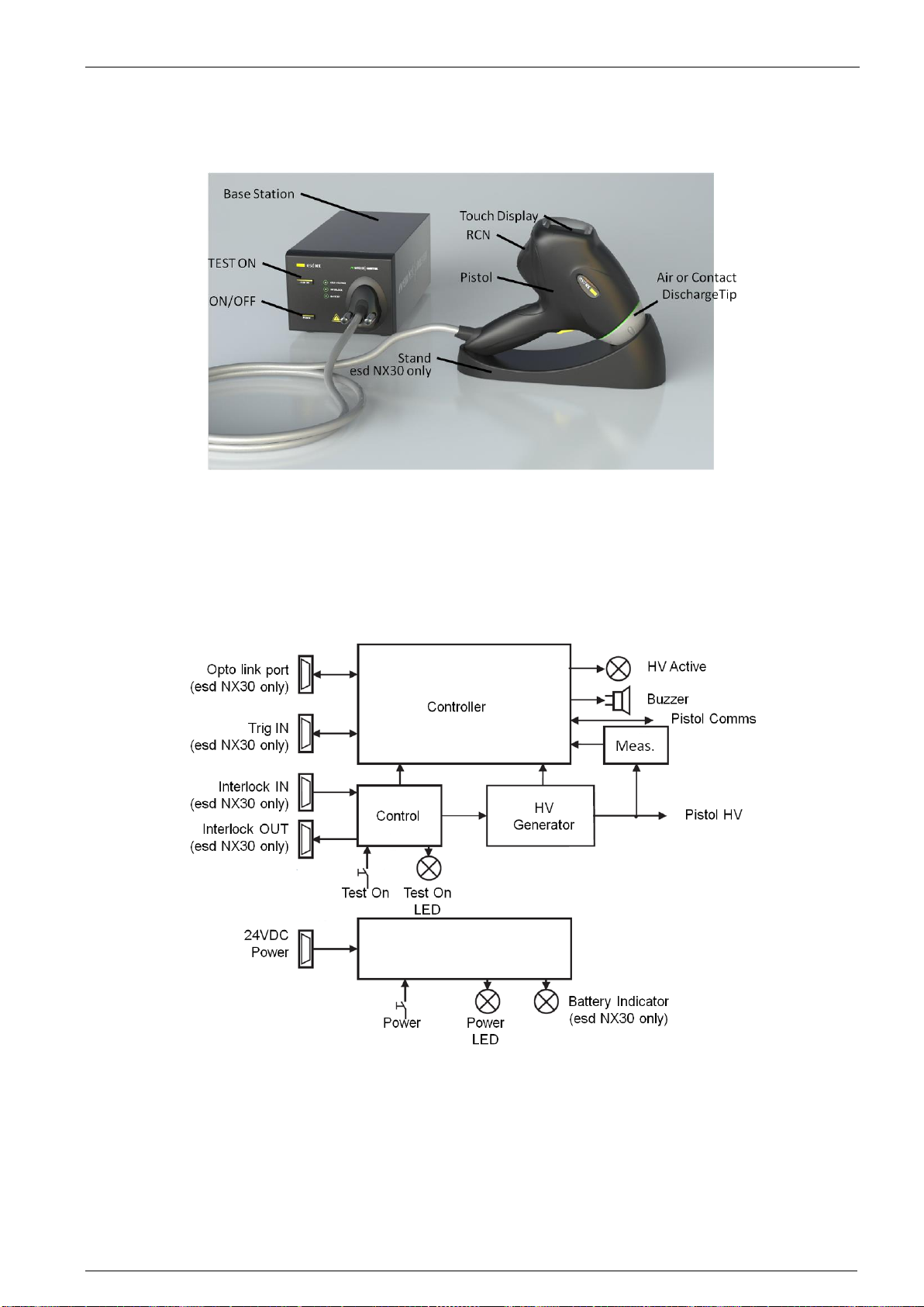
4.1.2 Block diagram
The various function units are shown in the block diagram:
Block diagram of the base station:
The microprocessor controls and monitors all the simulator functions:
•Touch-panel entries are checked for plausibility. Unacceptable entries are rejected and an acoustic warning notifies
the user of the error.
•Values entered are clearly shown on the large display screen. Further information shows the operating status and
the counter settings.
•The battery charge state is continuously monitored. The display warns if there is a tendency towards low voltage.
The instrument’s functions are inhibited once the battery voltage is insufficient to guarantee the pulse parameters.
•The actual tip is detected and the actual discharge mode will be shown.
EM Test esd NX30
Instruction Manual V 1.00.7 10 / 33
•High voltage generation is dynamically controlled by the processor. Varying load conditions, supply voltages, etc.
can thus be taken into account and have no effect on the pulse parameters.
•The instrument switches itself off automatically if it is not used for a while. The pulse parameters and operating
mode remain stored and ready for re-use.
•The charge voltage to the network is kept constant as long as the trigger is active. The high voltage is discharged
internally when the trigger is reset.
•If no discharge occurs when set for an air-discharge and the trigger is active, the processor waits for about 30 s
then autonomously resets the trigger and discharges the network internally with simultaneous acoustic warning.
•Pulse triggering is monitored. Once an arc has occurred the network is discharged internally so that no further arc-
ing is possible.
4.1.3 Operating elements
Apart from the trigger button itself (pulse triggering), all the operating elements, test-relevant setting and user information are
presented on the touch-sensitive display panel facing the operator.
The esd NX30 is switched on and off with the main power switch. The significance of the elements in the display field can be
seen in the following picture. Further information can be found in section "Operation".
All operations are performed via the touch-panel.
This is an example of a display shown on the panel when the pistol is switched on.
The function of the trigger button on the handgrip depends on the operating mode currently selected:
•As a pulse button in single discharge mode (1 pulse each time it is pressed).
•As an on / off switch in repetitive mode (discharges while button is pressed).
•As a pausing on / off switch in repetitive mode with the preset counter in operation (starts the discharges by press-
ing the button and stops the discharges by pressing the button again).
The remote control facility replicates the action of the trigger button by means of appropriate control signals.
4.2 System components
The basic set is packaged in a practical carrying case and comprises:
•Carrying case (esd NX30 only)
•ESD simulator esd NX30 consisting of pistol and base station with battery power supply
•Discharge network 150 pF/330 Ω to IEC / EN 61000-4-2 and ISO 10605
•1 each air and contact discharges tips
•Battery charger / mains power pack
•Pistol stand (esd NX30 only)
•Operating instructions
This set contains all the items necessary under normal conditions to conduct tests conforming to the IEC / EN 61000-4-2.

EM Test esd NX30
Instruction Manual V 1.00.7 11 / 33
4.2.1 Battery charger / power supply unit
Power to the instrument is provided through a universal mains unit suitable for input voltages between 80 and 240 VAC. This
same unit also serves as a charger for the integral battery pack.
Charging of the battery takes about three hours. At this point a timer switches the charger to a reduced charging current and
the indicator lamp changes from red to green.
The battery will also charge up when the instrument is switched off. A full battery charge will suffice for several days of nor-
mal test operation.
Battery life expectancy (esd NX30 only):
•The esd NX30 is designed to provide 30,000 discharges at the full 30 kV over many hours
•Ambient temperatures over 50°C can lead to degradation of the battery. If treated carefully, more than 300 charge /
discharge cycles can be expected without a noticeable reduction in capacity.
•The charger and battery-pack form a matched entity. The battery must not be charged from any other unit and the
charger is to be used exclusively for the intended purpose.
Operating advice:
•Use the equipment only in dry surroundings.
•Recharge the battery about every 6 months even if the instrument is not being used.
4.2.2 Options
A range of additional accessories is available for special applications and for testing to alternative standards:
•Discharge networks and test tips for other standards
•Fast rise time tip
•Coaxial measurement target
•Tripod adapter
•Opto link to a PC
•H-field adapter
•Flexible test tips
•External discharge remover
•Etc.
4.2.3 R/C Discharge Networks
The basic set contains a discharge network and tips for conducting tests that conform to IEC / EN 61000-4-2 (2008. Alterna-
tive networks can be installed for testing in accordance with other standards.
Several networks are given in the order list. The C and R values of the discharge network can also be specified for other
applications. Networks conforming to other standards can be built upon request. The only calibration method that is support-
ed is those according to IEC 61000-4-2.
Exchanging the discharge network is described in section "Exchanging the R/C network".
EM Test esd NX30
Instruction Manual V 1.00.7 12 / 33
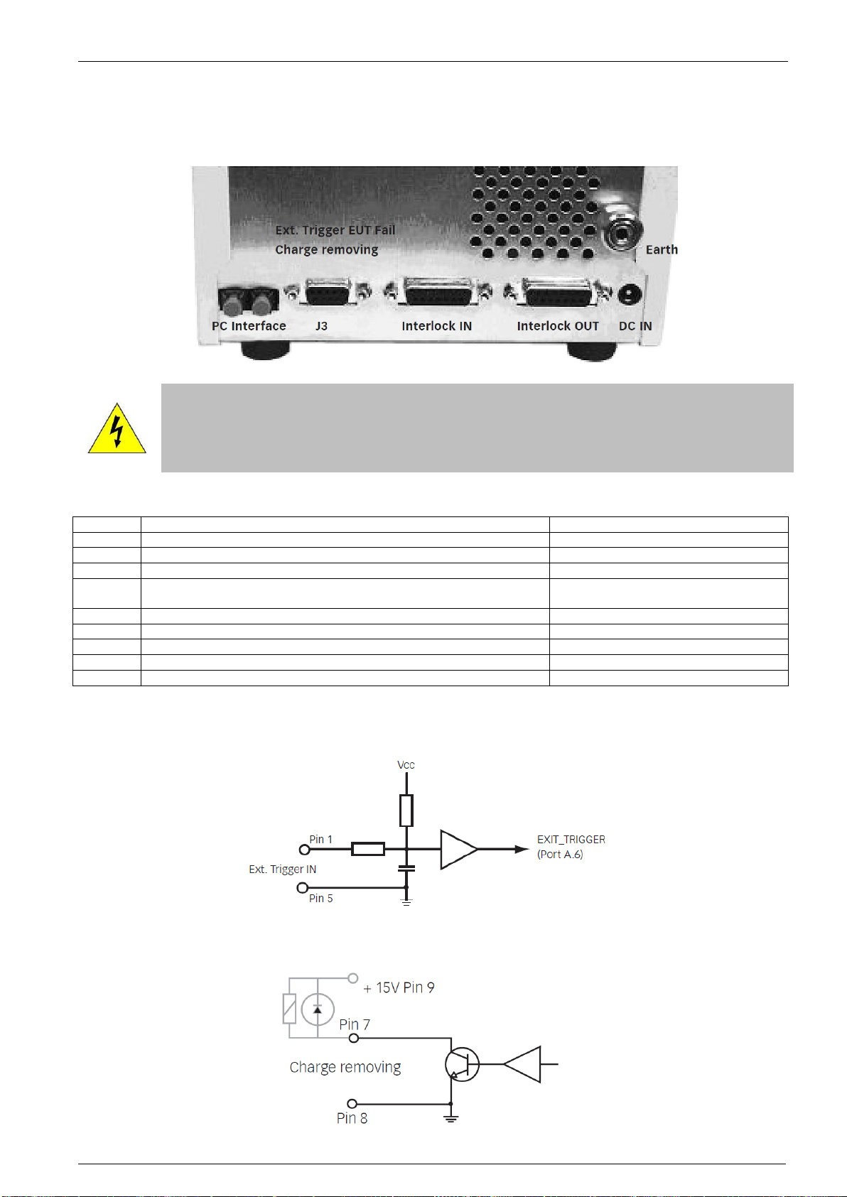
4.2.4 Remote triggering (esd NX30 only)
This port is indented to allow the user to connect external signals in order to remote control the esd NX30 generator, as well
as to connect external accessories like the charge removing device. See tables and graphs below for detailed signal descrip-
tion and drive circuitry information.
WARNING
Care has to be taken that the cable used to connect to this port is made with good shielding concept.
The shield itself needs to be linked with the housing such as to prevent any ESD hazard to the con-
troller board.
Connector J3: Pin Assignment
Pin
Signal Name
Description
1
EXT_TRIGGER
External trigger input
2
NC
-
3
NC
-
4
EUT_FAIL
EUT failure input
(reserved for future use)
5
GND
Earth
6
NC
-
7
Charge remove
Charge remover drive output
8
GND
Earth
9
+15V
Voltage output (max 500 mA)
Ext. Trigger (esd NX30 only):
The following circuit is built in behind the external trigger input connector. This function is similar to the function of the yellow
trigger knob on the handle. Trigger signal active low, i.e. to be pulled to ground.
Charge removing connection (esd NX30 only):
This function is to drive an external bleedoff switch option or an external relay.

EM Test esd NX30
Instruction Manual V 1.00.7 13 / 33
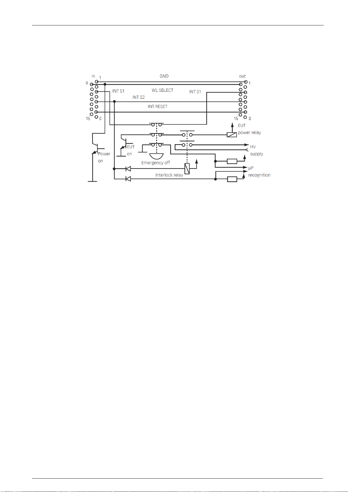
4.2.5 Interlock (esd NX30 only)
The esd NX30 has an integrated interlock system in accordance with standard practice for high voltage test equipment.
This system has the following functions:
Inputs
1. Input for external monitoring purposes of, for example, special coupling networks and access control.
2. Internal emergency off button opens the interlock.
Outputs
1. Operating mode: the esd NX30 can generate no high voltage as long as the interlock is not closed. High voltage genera-
tion is prevented if the interlock is opened during a test procedure.
2. Interlock output for other system devices.
The instrument is equipped with two 15-way connectors for interlock input and output. The interlock loop must always be
correctly terminated at both ends. In achieving this, the interlock wiring must connect all the safety contacts together.
An arbitrary number of instruments or accessories can be incorporated in this safety concept.
The high voltage supply can only be activated if the safety requirements in all the associated devices are fulfilled (emergen-
cy off buttons released, safety contacts closed).
The control of the warning lamps must make use of the interlock feature. The instruments can be switched on and the red
lamp lights up as soon as the interlock circuit is closed.
The pair of terminating connectors supplied must be utilized in the case of not making use of external interlock contacts.
Signal specifications:
Voltage 48VDC max.
Current 20mA min., 1A max
Connector
Socket, D-sub, 15 pin.
Max. permissible
cable length:
Correct operation guaranteed up to 10m (screened cable)
Operation should be insured via potential-free switch contacts.
All signals are active low, i.e. switched to GND.
The pin-out of the interlock input and output connector is identical. All the pins are connected together. The connection to pin
3 is made internally through the emergency off button. This link is broken when the internal interlock is activated.
Pin number
Function
1
Earth (GND), 0V
2
NC, linked through the other connector socket
3
Interlock input / output (connected inside the instrument)
4
NC, linked through the other connector socket
5
Interlock status (triggers the interlock function in the instrument by relay from +12 to +48 V)
6
NC, linked through the other connector socket
7
NC, linked through the other connector socket
8
NC, linked through the other connector socket
9
Switches warning lamps and peripherals on (active, provided that esd NX30 is switched from standby to
on).
10
NC, linked through the other connector socket
11
NC, linked through the other connector socket
12
NC, linked through the other connector socket
13
NC, linked through the other connector socket
14
NC, linked through the other connector socket
15
NC, linked through the other connector socket
Shell
Shielding
Wiring diagram for the interlock system:
EM Test esd NX30
Instruction Manual V 1.00.7 14 / 33
S: External safety switch (e.g. test enclosure hood, door contact, panic button, etc...)
Several interlock inputs of this type may be connected in series.
The contacts should be connected in series if numerous access barriers are necessary. Either one open contact or a voltage
of more than 1.5 V at the input is sufficient to disable the simulator.
EM Test esd NX30
Instruction Manual V 1.00.7 15 / 33
5 COMMISSIONING
Immediately upon receipt, check the instrument and the accessories for completeness and look for any transport damage.
Damage incurred in transit must be reported to the transportation undertaking without delay.
Before putting the instrument into operation:
•Study the manual
•Take the necessary safety precautions
•Charge the battery, if equipped (see section "Battery charger")
•Plug the interlock terminators into the base station, if equipped
•Connect the earth cable correctly
(the esd NX30 must never be switched on without a solid earth connection being made).
•Allow the instrument to dry out if any condensation has occurred
5.1 Function test
Switch the simulator on with the POWER switch.
The instrument performs audible switching operations for a few moments as it runs through a self-test and calibration proce-
dure. The instrument is ready for use once the self-test routines have been completed.
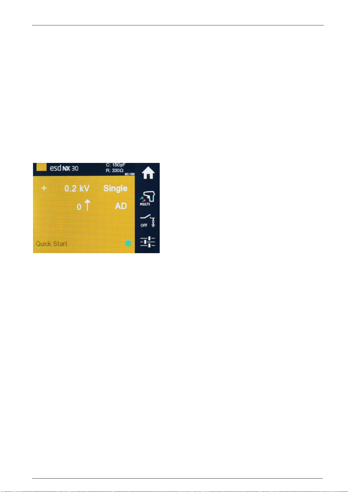
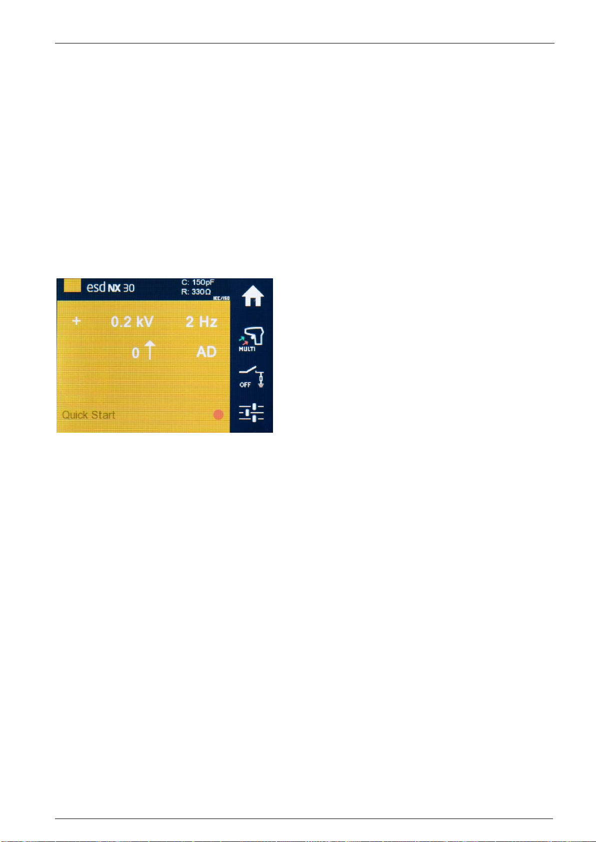
The display comes up with last used settings, and will look like this:
The “ready indicator” will be shown in red until the TEST ON button is pressed.
High voltage generation is activated by pushing the trigger button and keeping it pressed. By bringing the discharge tip close
to the earthing point an arc discharge occurs which is acknowledged acoustically.
EM Test esd NX30
Instruction Manual V 1.00.7 16 / 33
6 OPERATION
This section of the manual provides a guide through the numerous operating possibilities of the esd NX30.
The operation, hierarchically arranged, is therefore easy to remember. The display shows unmistakable information about
the parameters that have been set and the operating status of the simulator.
For safety reason, the instrument refuses to accept any invalid entries.
It is recommended to carry out the examples directly on the instrument (not forgetting to connect the earth cable!).
6.1 Switching on
Ensure the interlock terminators are plugged into the rear of the base station, if equipped, or otherwise the interlock loop is
complete.
Plug the pistol HV connector into the base station and tighten the screws.
ATTENTION
Ascertain that the earth cable for the pulse return path is solidly connected to the fixed installation’s earth
point.
There is a danger of electric shock if this is neglected!
Press the POWER button
Press the TEST ON button. The INTERLOCK LED will extinguish and the red HIGH VOLTAGE LED blinks while the pistol
runs it’s self-test and calibration routine.
The instrument is ready for use immediately after self-test and calibration procedures have been completed. High voltage
generation is activated by pressing and holding the trigger button. The active high voltage state is indicated on the base
station by a blinking LED.
Should a parameter need changing the operator has only to press on the relevant field in order to call up the appropriate
menu.
Successful air discharges are detected. A differentiation is made between this and the set value by the display "kV" flashing
green. If no valid discharge occurred, the display shows a "0" value and the kV symbol will flash red. The Threshold function
(see section "Threshold") permits various settings for the sensitivity of the breakdown voltage detector.
The effective discharge voltage depends on various factors such as the distance to the discharge point, speed of approach,
nature of the EUT, etc.
In the case of a contact discharge this measurement is not carried out since only a discharge current can occur.
The instrument switches itself off automatically after 15 minutes of non-use.
6.2 Battery monitoring (esd NX30 only)
The battery charge state is monitored continuously. An insufficiently charged or an empty battery is shown on the display.
Recharge the battery soon when this symbol is displayed. Correct operation and valid pulse parameters are still as-
sured.
The battery is more or less empty; its capacity is insufficient to maintain all the instrument’s functions. An appropri-
ate warning message is shown on the screen and all the instrument’s functions are inhibited.
A full battery will provide sufficient power for several days of normal test usage. The actual operating time depends, of
course, to a large extent on the conditions prevailing at the time.
The following figures have been obtained by way of reference:
•Battery freshly charged
•Contact-discharge with 30 kV
•More than 30’000 discharges can be generated
6.3 Operation and settings
The operation of the instrument and all settings are carried out by way of the touch-panel starting from the menu "TEST".
Generally, the following applies:
•Frames symbolize push buttons. Touching these sensitive areas causes a reaction, usually branching into another
menu.
•Values and indications that are not in frames are for information only. Pressing the trigger button always takes you
up one menu level higher.
•A virtual keypad appears in parameter setting menus.
•R / C value shown on main screen for convenient direct reading.

EM Test esd NX30
Instruction Manual V 1.00.7 17 / 33
6.3.1 Display mode
When adjusting some parameters, a keyboard and up / down buttons can be selected.
Numerical values (voltage, preset counter, random repetition times) can be entered just the same as with a pocket calcula-
tor.
Selection functions (such as language, type of discharge, program number, etc.) are handled by up / down buttons to scroll
through the settings.
6.3.2 Voltage
Touching the voltage indication brings you to the submenu for adjusting the discharge voltage. Set the required value and
press “Ok”.
6.3.3 Polarity
The polarity indication brings you into the relevant submenu. Choose between + or –. If the pre-select counter function is
active there is the further option of choosing alternating + / - polarity.
ATTENTION
Around the max. voltage range some minor delay for triggering shall have to be expected (fully discharging-
changing-recharging).

EM Test esd NX30
Instruction Manual V 1.00.7 18 / 33
6.3.4 Counter
Use the counter button to branch into the corresponding menu. Choose the counter mode: Preset counter on / off. In the On
state the counter content can be set. When the simulator is in operation the preset counter counts down until it reaches 0,
which then terminates the selected test sequence.
Reset counter sets the counter content to 0 or it reloads the preset counter with the previously selected value.
Pulse release behavior
Four modes of triggering are supported:
•Press to Start, Press to Stop
•Press to Start, Release to Stop
•Single (on Press)
•Single (on Release)

EM Test esd NX30
Instruction Manual V 1.00.7 19 / 33
6.3.5 Repetition
The repetition button takes you into the menu to select either single pulses or a repetition rate from 0.5 to 25 Hz in air dis-
charge, or from 0.5 to 20 Hz in contact discharge mode.
Four further repetition modes are available that trigger pulses with a statistical distribution over a specified period:
Random P: 1 –9999 pulses are triggered with a statistically distributed repetition rate ranging from a minimum of > 20 ms to
a maximum repetition rate of < 2000 ms.
Random T: Pulses are triggered during a period of 1 –9999 seconds with a statistically distributed repetition rate ranging
from a minimum of > 20 ms to a maximum repetition rate of < 2000 ms.
Free Adjust: For some specific requirements like R&D jobs or product standards, the prestored repetition times provided in
Hz may not match all needs. Allows entering values between 0.04 up to 300.00 s in 0.01 s steps.
6.3.6 Discharge Network
Depending on mounted tip the sign shows the actual discharge-mode AD (air discharge) or CD (contact discharge)
The R/C values for the relevant network are also shown. The corresponding value is automatically loaded.
Air-discharge = round test tip
Contact-discharge = sharp point test tip
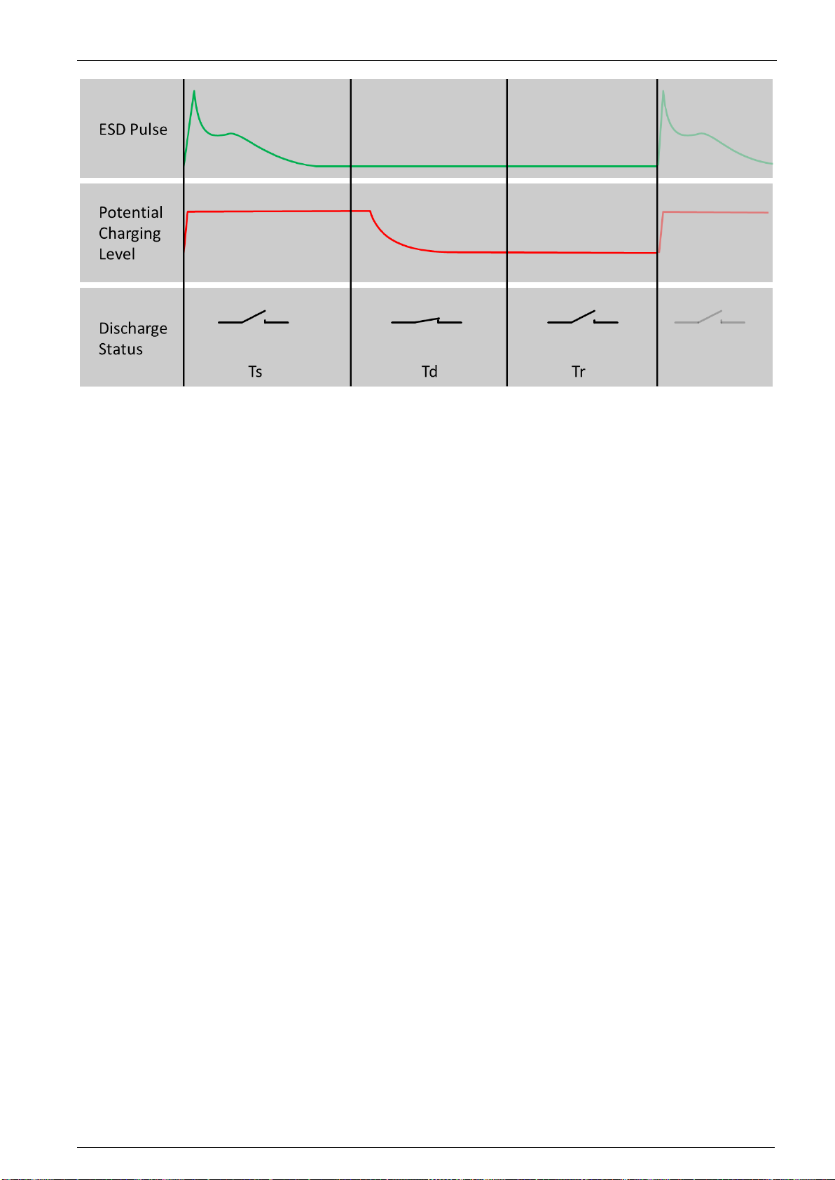
6.3.7 DUT Discharge Mode
The DUT discharge mode sets if an internal or external discharge should be used. For most users, Internal is correct.
A simple tap of the various timings will select the value, enabling the user to imput the time with the numeric keypad.
•Ts “shoot”. This is the minimum time that is used to shoot a pulse.
In contact discharge mode, this is quite precise, however in air discharge mode, the gun will wait up to a maximum
of 30s to allow the user to approach, and make contact to the DUT.
As soon as a valid discharge is detected, the discharge relay will go open circuit.
•Td “discharge” – the time used to discharge the DUT. During this time, the DUT will be discharged.
If internal mode is chosen in settings, the tip must remain in contact to the DUT to discharge any remaining energy
stored in the DUT.
•Tr “repetition”
The waiting time before the next discharge. The discharge relay is open circuit during this time.
•ON/OFF sets the DUT discharge function to on or off. This will take you immediately back to the home screen.
EM Test esd NX30
Instruction Manual V 1.00.7 20 / 33
EUT discharge on esd NX30/NX30.1: To remove the charged energy of a EUT, the simulator has an switch. With the time
of the charge removing procedure can be programmed. All timing parameters can be set from 0.1 up to 99 s in 0.1 s steps.
The DUT will be discharged during T2.
External EUT discharge on esd NX30: To remove the charged energy of a EUT, an external charge removing box can be
connected to the base station.
This manual suits for next models
1
Table of contents
Other EMTEST Test Equipment manuals

EMTEST
EMTEST dito User manual

EMTEST
EMTEST PFS 200N Series Instruction Manual

EMTEST
EMTEST VDS 200Q10 Series User manual

EMTEST
EMTEST CNI 508 N2 User manual

EMTEST
EMTEST AN 200 Series Instruction Manual

EMTEST
EMTEST PFM 200N200 User manual

EMTEST
EMTEST variac-NX 1-260-16 User manual

EMTEST
EMTEST CWS 500A / 75 User manual

EMTEST
EMTEST CNI 503 Series Technical Document

EMTEST
EMTEST PFM 200N100.1 User manual


