Enable Lifecare Aria + Operator's manual

Aria+
USER INSTRUCTION MANUAL
Product name
to go here
Product description to go here
USER MANUAL
enablelifecare.com.au
Aria
Pressre Care System
+

Aria+2
Aria+ is a pressure relieving mattress suitable for use with patients at VERY HIGH RISK of pressure
ulcer damage. Oering high levels of patient comfort, this unique system has the facility to “step
up” to that of a dynamic mattress when clinically required. Similarly, the mattress’s function can be
downgraded as the patient’s condition improves. These features make it particularly beneficial for use
within the patient’s home or palliative care environment and help reduce logistic and decontamination
costs. The clinical benefits of a single system are equally applicable to those of a modern hospital
setting. A higher maximum weight capacity, up to 39 stone / 250kg, allows the product to meet the
modern challenges of those heavier clients. All component parts are interchangeable and replaceable,
maximising product life and reducing environmental impact.
The Mattress consists of a foam head cell and series of 7 pairs of transverse air cells, each containing
a unique foam profiled insert, which are in turn held within a foam U Core, all protected by a vapour
permeable waterproof cover. The single pillow end consists of foam only. The transverse cells are
arranged into alternate pairs of A and B cells which are filled and emptied in sequence.
In Static Mode, the mattress attains the pressure reducing properties of the Gio-Form Care Foam
mattress (details available on request), whilst in Alternating Mode the mattress is able to oer similar
properties to a pressure relieving dynamic system.
The digitally controlled Power Unit controls a pump that allows air to flow into, or out of the air cells
as required according to the operating mode selected. It also maintains the air pressure within the
mattress at the required level and controls the action of the audible/visual Audible Warning system in
the event of mains supply failure or over or under inflation pressure. A CPR Valve located at the pump
end of the umbilical hose permits the rapid deflation of the Mattress in an emergency.
1. Introduction
A
A
B
B
A B A B
Aria+3
NOTE: Please ensure that all securing straps on the base of
the mattress are secured onto the NON MOVING PARTS of
the bed frame. For shut down procedure, see 4.2 Power Unit
(Pump) section.
Note: Please ensure that all securing straps on the base of
the mattress are secured onto the
NON MOVING PARTS of the bed frame.
For shut down procedure, see 4.2 Power Unit (Pump)
section.
Power Switch Audible Warning Reset
The power switch simply switches the mains power to
the pump on and off. When the pump detects an Audible
Warning condition, this can be silenced as below and re-
set by switching the pump off and then back on again.
CPR Valve
Please ensure that the CPR connector is always placed
fully home, prior to inating the mattress.
NB: The mattress will NOT inate properly should this not
be the case. The CPR connector is only to be used in the
event of a clinical emergency for priority use. However,
disconnecting this function will cleverly deate air rapidly
from the mattress in readiness for transport / static mode.
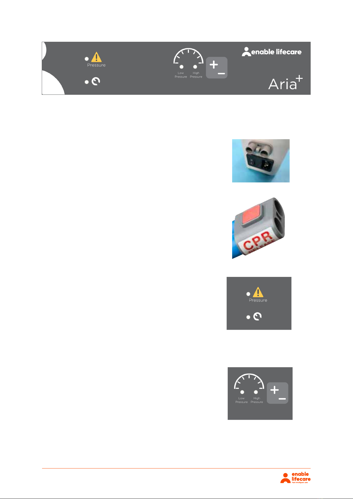
Warning Modes
There are two red LEDs which inform the user of potential
problems with the mattress system.
The yellow warning triangle denotes a pressure issue in
the mattress.
Low Pressure Alarm:- The red LED will ash slowly whilst
an audible alarm also sounds. Check all hose connections
High Pressure Alarm:- The red LED ashes rapidly whilst
an audible alarm also sounds.
System Failure:- The red LED next to the spanner will
ash and an audible alarm also sounds.
Pressure Settings
The +/- button is used to adjust the pressure from Low
pressure to High pressure. The left hand LED denotes
Low pressure selected. The right hand LED denotes High
pressure selected.
The power switch simply switches the mains power to the
pump on and o. When the pump detects an Audible Warning
condition, this can be silenced as below and reset by switching
the pump o and then back o againi.
Please ensure that the CPR connector is always placed fully
home, prior to inflating the mattress.
NB: The mattress will NOT inflate properly should this not be
the case. The CPR connector is only to be used in the event of
a clinical emergency for priority use. However, disconnecting
this function will cleverly deflate air rapidly from the mattress
in readiness for transport / static mode.
There are two red LEDs which inform the user of potential
problems with the mattress system.
The yellow warning triangle denotes a pressure issue in the
mattress.
Low Pressure Alarm: The red LED will flash slowly whilst an
audible alarm also sounds. Check all hose connections
High Pressure Alarm: The red LED flashes rapidly whilst an
audible alarm also sounds.
System Failure: The red LED next to the spanner will flash and
an audible alarm also sounds.
The +/- button is used to adjust the pressure from Low pressure
to High pressure. The left hand LED denotes Low pressure
selected. The right hand LED denotes High pressure selected.
Power Switch Audible Warning Reset
CPR Valve
Warning Modes
Pressure Settings

Aria+
4.1. Mattress
4.2. Power Unit (Pump)
4
Aria+ can be used as a pressure reducing mattress for patients at High Risk of pressure ulcer damage
without the need to attach the pump.
If/When required, the Aria+ can be used as an alternating mattress system by attaching the Aria+
pump system. No other system should be attached to the mattress as the design settings and internal
air pressure properties of the Aria+ pump are specific to this mattress only.
The Aria+ is a replacement mattress system and should NOT be placed on top of any existing mattress.
Hang the Power Unit (Pump) onto the foot board. The mounting hooks swivel to suit the thickness
of the foot board or rail. Connecting the Umbilical Hose to the Power Unit (Pump), place the 3-pin
electrical plug into the wall outlet and switch on:
Attach the Blue Umbilical Hose to the Power Unit (Pump) by connecting the air connector at the end
of the Umbilical Hose to the air inlet connector at the bottom left hand side of the pump. Ensure that
the Red CPR Release button is located on top of the Air Inlet connector after connection is complete.
Attach the mains cable to the pump by inserting the “kettle” type connector into the recess located
on the left hand side of the pump. The mains cable has been designed specifically as a removable
part to aid in easy replacement should it become damaged in use.
The mains plug should be turned o and removed from wall socket as a means of isolation.
Plug the mains cable into a suitable 230v mains socket and switch on the Power Unit using the on/
o switch.
After the pump has been turned on both the “Hi “and the “Lo” lights will flash together intermittently
until the pump has attained its initial operating pressure. Once the pump has attained its initial
operating pressure the “Lo” light will stay on constantly and the mattress is ready for use.
Place the Aria+ directly on to the bed platform ensuring that the Blue multi-stretch waterproof cover
is on top and that the umbilical hose is located at the left hand corner at the foot end of the bed. Only
Dartex material is used to construct the top covers.
Cover the Mattress with a loose fitting sheet.
The start up time from static to dynamic mode is immediate.
Shut down is the reverse of above.
Static Mattress Use
Alternating Mattress Use
5. Operation

Aria+5
5.1. Lo / Hi Settings
5.3. Troubleshooting
5.2. CPR Deflation
The Aria+ Mattress, in Alternatinig Mode, has two pressure settings. The initial setting that the pump
will revert to upon set up is “Lo”. The “Lo” comfort setting is ideal for the lighter patient or those
who feel discomfort when on a normal alternating air type mattresses system. However, for patients
with existing pressure damage or those at Very High Risk, it is recommended that dependant on
the clinical judgement of the clinician, the “Hi” setting is activated by pressing the +/- button once,
which is located on top of the pump. In “Hi” Mode the pump attains more of the characteristics
of an alternating air mattress system whilst still utilising the advantages of the static foam insert.
Repeatedly pressing the ‘mode’ button enables the Lo & Hi modes to be selected in turn.
For assistance (if needed) in setting up, using or maintaning the Aria+, or to report unexpected
operation or events, please contact Enable Lifecare on the contact details on the reverse of this
manual.
The CPR system consists of a manually operated button located on the Air Inlet connector attached
to the pump. By pressing the Red Button, which will release the connector locking system, the user
can remove the connector unit which will deflate the mattress air system back to that of a static foam
mattress.
NOTE: After a short period as the Mattress deflates the ‘Low Pressure’ Audible Warning is activated
and can be cancelled by switching the Power Unit o.
To change the location of the mattress, remove the Umbilical cord and allow the mattress to return
to its Static Mattress form. Switch o the Power Unit (Pump) using the on/o switch and disconnect
the electrical supply cable from the mains socket. The mattress can now be moved to a new location
where it must immediately be reconnected to the mains electrical supply and the Power Unit (Pump)
switched back on. Once the Mattress has been refilled, the ‘Alternating’ mode will automatically revert
back to the Lo setting and should be reselected to Hi should this be desired by the clinician.
6. Transportation
The Mattress will not ‘alternate’ when disconnected from the Power
Unit (Pump) and /or the mains electrical. Also refer to environmental
conditions section at rear of this manual.
WARNING
!
Table of contents
Other Enable Lifecare Medical Equipment manuals


Popular Medical Equipment manuals by other brands


Getinge
Getinge Arjohuntleigh Nimbus 3 Professional Instructions for use

Mettler Electronics
Mettler Electronics Sonicator 730 Maintenance manual

Pressalit Care
Pressalit Care R1100 Mounting instruction

Denas MS
Denas MS DENAS-T operating manual

bort medical
bort medical ActiveColor quick guide

AccuVein
AccuVein AV400 user manual


