Enable Lifecare Nimble204 Owner's manual
Nimble204
Nimble204
Installation and Operation Instructions
Product name
to go here
Product description to go here
USER MANUAL
enablelifecare.com.au
Portable Ceiling Lifter

Nimble204
Introduction
Application
Description
Symbols Used in this Manual
Markings
Safety Instructions
Technical Specifications for Nimble204
Anatomy of the Nimble204
Basics in Transferring a Patient
Installing the Nimble204 in the Gantry
Installing the Endstop on the Gantry
Labeling the Tracks
Using the Reacher Bar
Magnetic Connection of the Hand Control to the Nimble204
Operating the Nimble204
Charging the Nimble204
LED and Buzzer Functions
Emergency Stop
Emergency Lowering
Manual Emergency Lowering
Overspeed Cam
Cleaning and Disinfection
Troubleshooting
Inspection and Maintenance
Nimble204 Accessories
GoTrack Systems and Support Structure
Environmental Conditions
Electro-Magnetic Compliance Data for GoLift Portable450
Warranty
3
5
6
7
9
9
10
11
12
12
13
13
14
15
16
16
16
17
17
18
19
20
21
22
26
2
Table of Contents
Nimble204
APPLICATION
DESCRIPTION
Contents of Packaging
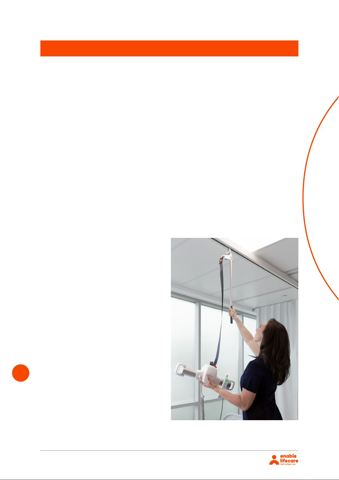
The primary purpose of the Nimble204 portable system is to safely lift and transfer a patient within
an institutional setting or at home. The Nimble204 allows these transfers with as little eort as
possible for the caregiver, while providing dignity to the patient. A ceiling lift is simple and safe for
the caregiver as well as the patient. The lift can be easily moved by a caregiver along the track from
one location to another.
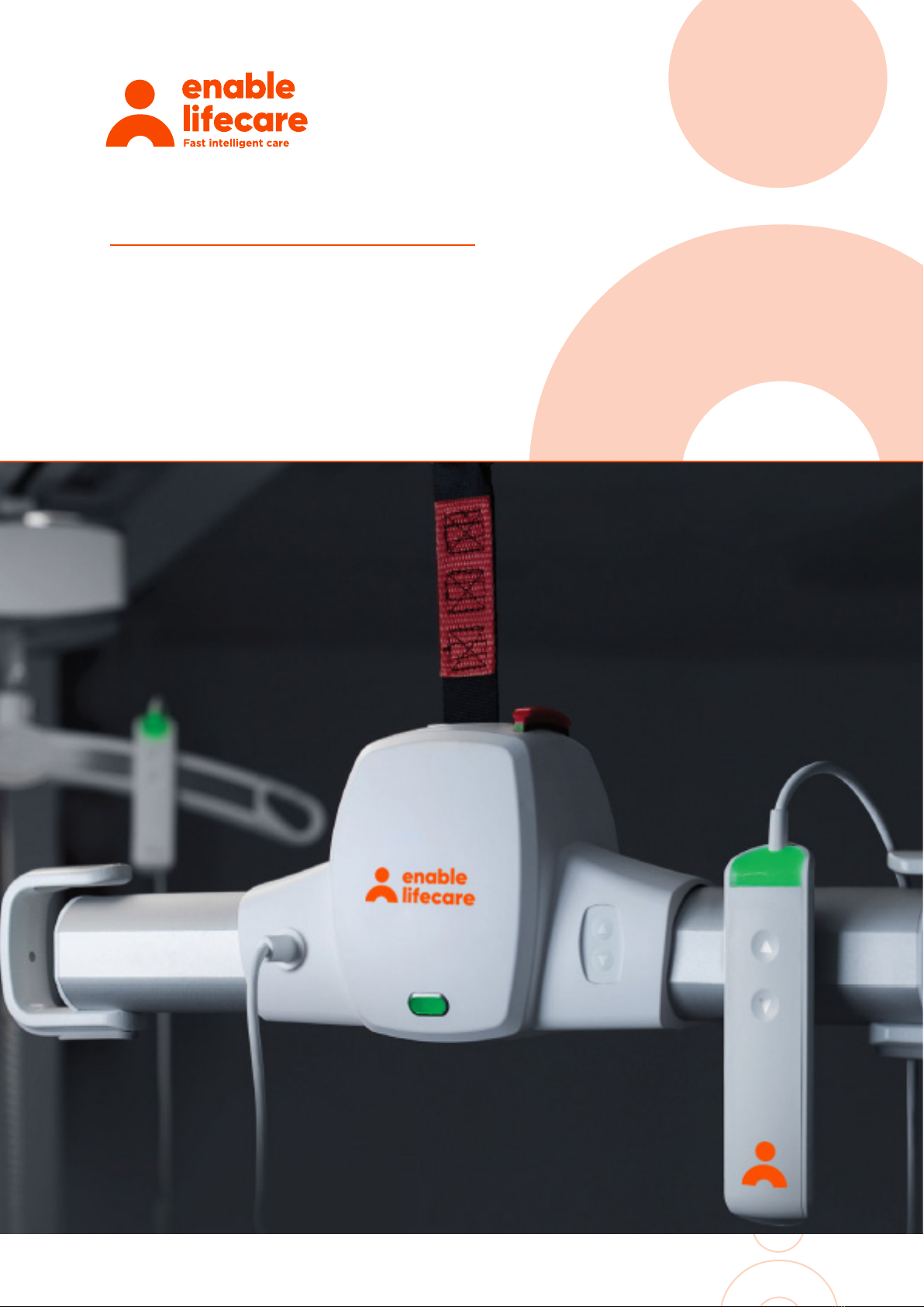
The Enable Lifecare Nimble204 portable lifter is an ideal ceiling lift system designed for routine
transfers of patients. The most compact portable lift in its class, the Nimble204 is designed to be
aesthetically pleasing to both the caregiver and the patients. In an eort to address infection control
requirements, we gave careful consideration to the smooth edges and rounded corners of our ceiling
lift, carry bar and hand control. When you look under the cover of this compact lift, you will find an
impressive set of all metal gears and state-of-the-art battery technology that will allow the caregiver
to safely, and eortlessly transfer a patient weighing up to 450 lbs on a single lift.
The Nimble204 weight capacity is 450 lbs. This weight limit must not be exceeded.
The Enable Lifecare Nimble204 can be installed in a variety of track profiles (the trolley can
becustomized to fit these track profiles) and it also works seamlessly with the Enable Lifecare Patient
Lift Pendant (PLP) System.
Upon receipt of the packages, verify it against
the packing slip to ensure the shipment is
complete and inspect the equipment for
possible damage. If there is any damage,
DO NOT USE the equipment and notify the
carrier immediately to file a claim. Provide
complete information concerning damage
claims or shipping errors toEnable Lifecare.
Include all equipment identification numbers
along with a description of the damaged
parts.
a. Enable Lifecare Nimble204 Portable Lifter
b. Hand Control
c. Charger
d. Owner’s Manual
e. Portable Trolley
3
Introduction
Nimble204 4
Introduction
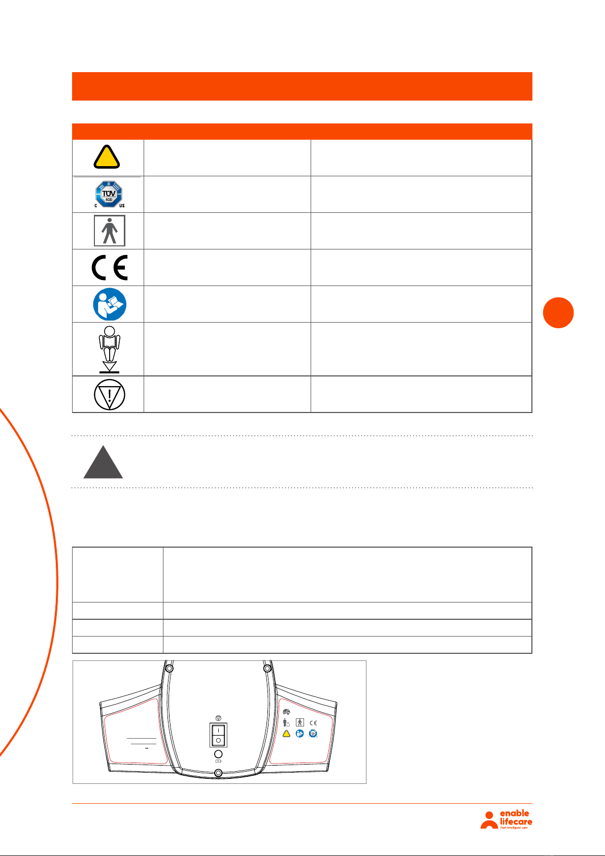
Symbol Reference Title
ISO 7000-0434A Caution risk of danger
TUV Certified by TUV
IEC 60417-5840 Type BF Applied Part
CE Certification of Conformity
ISO 7010-M002 Refer to instruction manual/booklet
Amico Mobility Emergency Lowering
Amico Mobility Emergency Stop
Standard(s): CAN/CSA-C22.2 No. 60601-1:08 Medical Electrical Equipment – Part 1: General
requirements for basic safety and essential performance. ISO10535:2006
Hoists for the transfer of disables persons – Requirements and Test Methods.
CAN/CSA-C22.2 60601-1-11:2-15 home use environments.
Product: Nimble204
Brand Name: Nimble204
Models 450 lbs
4Amico Mobility Solutions Corporation
SYMBOLS USED IN THIS MANUAL
Symbol Reference Title
!
ISO 7000-0434A Caution risk of danger
TUV Certified by TUV
IEC 60417-5840 Type BF Applied Part
CE Certification of Conformity
ISO 7010-M002 Refer to instruction manual/booklet
Amico Mobility Emergency Lowering
Amico Mobility Emergency Stop
Introduction
AJW Technology Consulting GmbH
Königsallee 106
40215 Dusseldorf
Germany
REV.
DESCRIPTION
BY
DATE
5
4
3
1
122B East Beaver Creek Rd.
Richmond Hill, ON, L4B 4V1, CANADA
Tel: (905)764-0800
Fax: (905)764-0862
DESCRIPTION:
PART NO:
SHEET:
OF
DRAWING NO:
11
PROJECTION
PRIVATE AND CONFIDENTIAL
THIS PRINT IS PROPERTY OF AMICO CLINICAL AND IS LOANED IN CONFIDENCE SUBJECT TO RETURN UPON
REQUEST AND WITH THE UNDERSTANDING THAT NO COPIES ARE TO BE MADE WITHOUT THE CONSENT OF
AMICO CLINICAL.
ALL RIGHTS TO DESIGN OR INVENTION ARE RESERVED
2021-03-18
DATE:
2021-03-18
DATE:
VC
CHECKED BY:
AC
DRAWN BY:
NTS
SCALE:
2
A
B
C
D
SEE NOTE 2
FINISH:
MATERIAL:
SEE NOTE 1
YYMMDD-XXX
UNLESS SPECIFIED:
ALL DIMENSIONS IN INCHES
SURFACE FINISH 63 uin
BREAK ALL EDGES 0.005 - 0.010
REMOVE SHARP EDGES AND BURRS
ANGLE TOLERANCES
0.25
CONCENTRICITY OF 0.005"
STRAIGHTNESS & FLATNESS
PARALLELISM OF 0.005"
DECIMAL TOLERANCES: X.XX
.05
X.XXX
.005
X.XXXX
.0005
Assem1^GO-LIFT-PORT-450-WR
Amico Mobility Solutions Corporation
Email: amo-service@amico.com
1. 8 7 7. 4 6 2 . 6 4 2 6
M
A
D
E
I
N
N
O
R
T
H
A
M
E
R
I
C
A
!
Charger : Wall Industries 36V 1.11 A 40W
Duty Cycle: 1 M in ON / 9 Min OFF
Serial #:
Mfg. Date:
GLP450-9999
450 lbs (205 kg)
IP23
7.315
A A
B B
4
4
3
3
2
2
1
1
Back
Front
0.8341”
1.6256”
!
WARNING: This symbol is intended to alert the user of hazard or unsafe practices, which could result in
serious bodily harm.
MARKINGS
The GoLift Portable450 is designed to comply with the following Standards:
Standard(s): CAN/CSA-C22.2 No. 60601-1:08 Medical Electrical Equipment – Part 1: General requirements for
basic safety and essential performance. ISO10535:2006 Hoists for the transfer of disables persons –
Requirements and Test Methods. CAN/CSA-C22.2 60601-1-11:2-15 home use environments.
Product: Amico GoLift Portable
Brand Name: GoLift
Models: 450 lbs
WARNING This symbol is intended to alert the user of hazard or unsafe
practices, which couuld result in serious bodily harm.
!
MARKINGS
The Nimble204 is designed to comply with the following Standards
4Amico Mobility Solutions Corporation
SYMBOLS USED IN THIS MANUAL
Symbol Reference Title
!
ISO 7000-0434A Caution risk of danger
TUV Certified by TUV
IEC 60417-5840 Type BF Applied Part
CE Certification of Conformity
ISO 7010-M002 Refer to instruction manual/booklet
Amico Mobility Emergency Lowering
Amico Mobility Emergency Stop
Introduction
AJW Technology Consulting GmbH
Königsallee 106
40215 Dusseldorf
Germany
REV.
DESCRIPTION
BY
DATE
5
4
3
1
122B East Beaver Creek Rd.
Richmond Hill, ON, L4B 4V1, CANADA
Tel: (905)764-0800
Fax: (905)764-0862
DESCRIPTION:
PART NO:
SHEET:
OF
DRAWING NO:
11
PROJECTION
PRIVATE AND CONFIDENTIAL
THIS PRINT IS PROPERTY OF AMICO CLINICAL AND IS LOANED IN CONFIDENCE SUBJECT TO RETURN UPON
REQUEST AND WITH THE UNDERSTANDING THAT NO COPIES ARE TO BE MADE WITHOUT THE CONSENT OF
AMICO CLINICAL.
ALL RIGHTS TO DESIGN OR INVENTION ARE RESERVED
2021-03-18
DATE:
2021-03-18
DATE:
VC
CHECKED BY:
AC
DRAWN BY:
NTS
SCALE:
2
A
B
C
D
SEE NOTE 2
FINISH:
MATERIAL:
SEE NOTE 1
YYMMDD-XXX
UNLESS SPECIFIED:
ALL DIMENSIONS IN INCHES
SURFACE FINISH 63 uin
BREAK ALL EDGES 0.005 - 0.010
REMOVE SHARP EDGES AND BURRS
ANGLE TOLERANCES
0.25
CONCENTRICITY OF 0.005"
STRAIGHTNESS & FLATNESS
PARALLELISM OF 0.005"
DECIMAL TOLERANCES: X.XX
.05
X.XXX
.005
X.XXXX
.0005
Assem1^GO-LIFT-PORT-450-WR
Amico Mobility Solutions Corporation
Email: amo-service@amico.com
1. 8 7 7. 4 6 2 . 6 4 2 6
M
A
D
E
I
N
N
O
R
T
H
A
M
E
R
I
C
A
!
Charger : Wall Industries 36V 1.11 A 40W
Duty Cycle: 1 M in ON / 9 Min OFF
Serial #:
Mfg. Date:
GLP450-9999
450 lbs (205 kg)
IP23
7.315
A A
B B
4
4
3
3
2
2
1
1
Back
Front
0.8341”
1.6256”
!
WARNING: This symbol is intended to alert the user of hazard or unsafe practices, which could result in
serious bodily harm.
MARKINGS
The GoLift Portable450 is designed to comply with the following Standards:
Standard(s): CAN/CSA-C22.2 No. 60601-1:08 Medical Electrical Equipment – Part 1: General requirements for
basic safety and essential performance. ISO10535:2006 Hoists for the transfer of disables persons –
Requirements and Test Methods. CAN/CSA-C22.2 60601-1-11:2-15 home use environments.
Product: Amico GoLift Portable
Brand Name: GoLift
Models: 450 lbs
Nimble204
• The Nimble204 must be installed only by personnel authorized by Enable Lifecare.
• Do not use this equipment prior to understanding the contents of this manual.
• Contents of this manual are subject to change without prior notice to users. Keep for future reference.
• Never place the Nimble204, track/PLP and sling(s) in control of a person who has not been properly
trained in the use and care of this equipment.
• The Nimble204 and associated Track/PLP and sling(s) are for transferring patients only. Never use the
Nimble204 for any other purpose.
• Enable Lifecare’s Warranty is void if unauthorized personnel perform service on the Nimble204 system.
• In facilities where more than one caregiver is responsible for using the Nimble204 and associated track
and slings, it is important that all caregivers be trained in the proper use of this equipment. A training
program should be established by the facility to familiarize new caregivers with this equipment.
• Do not expose the Nimble204 directly to water. Warranty does not cover any misuse or abuse of the
Nimble204.
• The Nimble204 should be inspected and maintained on a regular basis to keep it operating safely and
correctly.
• Any accessories used with the Nimble204 including the track/PLP and sling(s) should be checked to
ensure that they are in good working order. Check for signs of tear or fraying prior to use. Report any
unusual wear or damage immediately.
• Amico Mobility will not be responsible for any damage caused by misuse, neglect or purposeful
destruction of the lift and its associated components. Do not attempt to modify/alter the Nimble204.
• Do not in any circumstance exceed the maximum allowable load of this lift. Refer to the “Technical
Specifications” section of this manual and/or the labels on the lift.
• The installation of the lift, track and sling are certified to a maximum load. Do not exceed the maximum
rated load of any of the components.
• There is a risk of explosion if the lift is used in the presence of flammable anesthetics.
• The Nimble204 should be decommissioned/disposed of after the recommended service lift in accordance
with local law regulations.
• If the battery case cracks and the contents of the battery contact your skin or clothing rinse immediately
with warm water.
• If the contents of the battery contact your eyes, rinse immediately with plenty of water and seek medical
attention.
• If the contents of the battery can cause respiratory irritation, provide fresh air and seek medical attention.
5
Safety Instructions
WARNING
WARNING
READ THESE INSTRUCTIONS CAREFULLY OR SERIOUS
INJURY MAY OCCUR
There are no known contraindications associated with the
use of the Nimble204 and it’s accessories, provided they are
used per our recommendations and guidelines
!
!
However, for any independent users of the Nimble204, it is extremely important that the patient is
able to receive assistance during the transfer in the event of an equipment failure. This assistance can
be provided in the form of; a nearby qualified caregiver, a phone, or other communication device.
Nimble204
Maximum Lifting Speed: Approvals:
Unit Weight:
Expected Service Life:
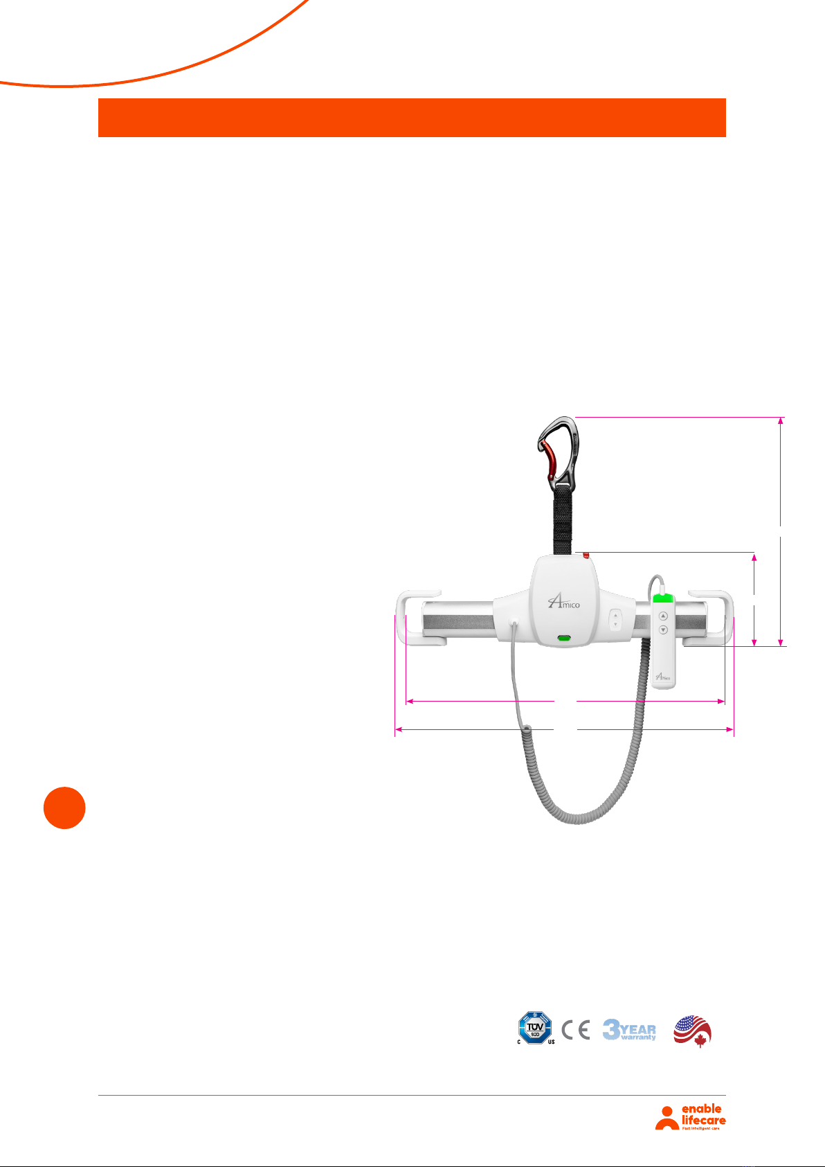
Safe Working Load (SWL):
Dimensions (see diagram):
Number of Lifts per Charge (Duty: 10/90):
Lift Case:
Batteries:
Hand Control:
Safety:
No load: 1.7 inches/second
150 lbs/68 kg: 1.3 inches/second
450 lbs/204 kg: 1.0 inch/second
CAN/CSA-C22.2 No 60601-1:08
CAN/CSA-Z10535.1:15
6 lbs
22,500 cycles or 10 years.
It is recommended that the lift be replaced
after this time.
The expected life of slings, batteries fuses,
straps and cord is dependent upon proper
maintenance.
450 lbs
Length: 19.4” (49.27 cm)
Height: 5.2” (13.20 cm)
Depth of Lift: 3.7” (9.398 cm)
Strap Length: 74” (187.96 cm)
78 with 150 lbs (25% of strap at midrange)
46 with 450 lbs (25% of strap at midrange)
Charging time: 2-4 Hours
Flame retardant ABS
IP23 Lift - protected from fingers and water
spray less 60 degrees from vertical
High Capacity, Long Lasting NiMH
1 x 24V (1.6Ah)
IPX4 Hand Control – protects from splashing
water, no matter the direction
Emergency Stop
Emergency Lowering Device: Independent Circuit
Manual Lowering
Upper Limit Detection
Lower Limit Detection
Slack Tape Sensor
Free Fall Brake (Over Speed Governor)
Low Battery and Dead Battery Alarms
Soft Start and Stop
Overload Protection
6
Technical Specifications for Nimble204
6Amico Mobility Solutions Corporation
Maximum Lifting Speed:
No load: 1.7 inches/second
150 lbs/68 kg: 1.3 inches/second
450 lbs/204 kg: 1.0 inch/second
Unit Weight:
6 lbs
Safe Working Load (SWL):
450 lbs
Dimensions (see diagram):
Length: 19.4" (49.27 cm)
Height: 5.2" (13.20 cm)
Depth of Lift: 3.7" (9.398 cm)
Strap Length: 74" (187.96 cm)
Number of Lifts per Charge (Duty: 10/90):
78 with 150 lbs (25% of strap at midrange)
46 with 450 lbs (25% of strap at midrange)
Charging time: 2-4 Hours
Lift Case:
Flame retardant ABS
IP23 Lift - protected from fingers and water spray less 60
degrees from vertical
Batteries:
High Capacity, Long Lasting NiMH
1 x 24V (1.6Ah)
Battery Charger:
Input: 100-240VAC
Output: 36VDC, 40 Watt, 1.0A
Hand Control:
IPX4 Hand Control – protects from splashing water, no
matter the direction
Safety:
Emergency Stop
Emergency Lowering Device: Independent Circuit
Manual Lowering
Upper Limit Detection
Lower Limit Detection
Slack Tape Sensor
Free Fall Brake (Over Speed Governor)
Low Battery and Dead Battery Alarms
Soft Start and Stop
Overload Protection
Technical Specifications for Amico GoLift Portable450
M
A
D
E
I
N
N
O
R
T
H
A
M
E
R
I
C
A
Approvals:
CAN/CSA-C22.2 No 60601-1:08
CAN/CSA-Z10535.1:15
Expected Service Life:
22,500 cycles or 10 years.
It is recommended that the lift be replaced after this time.
The expected life of slings, batteries fuses, straps and cord is
dependent upon proper maintenance.
18.2"
19.4"
81"
5.2"
Nimble204 7
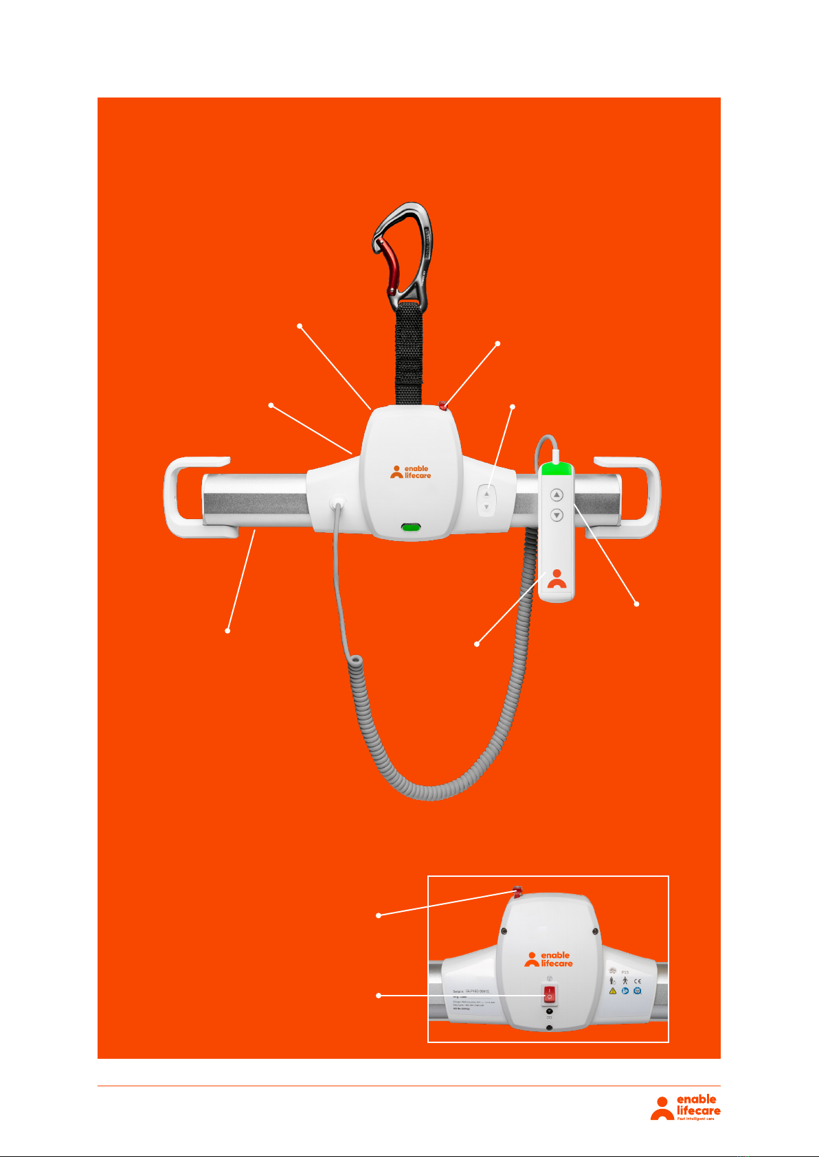
Anatomy of the Nimble204
Emergency
lowering
Durable all
metal gears
Lifts up to
204 kg!v
Nimble204 weighs
less than 3kg!
Quick magnetic
hand control
connection
Emergency lowering
Back of the Nimble204
Emergency stop
Wired hand
control
Unit controls
Nimble204 8
Technical Specifications for Nimble204
LIFTING SLING
WORKING WITH THE NIMBLE204
ATTACHING THE LIFTING SLING
LIFTING TO AND FROM A SEATED
POSITION
A lifting sling with four to six straps designed for
mounting on hooks should be used with the Nimble204
lift.
Enable Lifecare shall not be liable for faults or accidents
due to incorrect use of the lifting sling, or for reasons
of inadequate attention on the part of the caregiver or
patient.
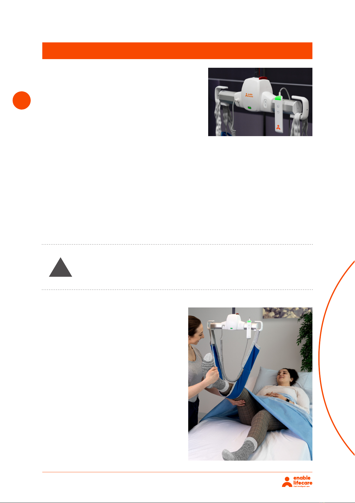
The Nimble204 moves freely in the track system and does not have any special requirements for
space or power in connection with moving. Attention can be fully focused on the user’s functional
level and the caregivers technique.
To use the Nimble204 correctly, the patient should only be lifted to the extent that she/he is clear of
the surface and should be moved at this height.
Place the straps from the lifting sling on the hooks of the Nimble204 Start with the uppermost set of
straps (from the back) and then take the lowest set of straps (from the legs).
WARNING
Be careful when attaching the lifting sling on the hooks.
Check that the straps have been completely through the
opening and into place in the Portable lift hooks.
When pressing the up button to lift the patient, check again
that all straps remain correctly placed.
!
• When lifting a patient from e.g. a wheelchair, move
the Nimble204 towards the patient to be lifted.
• The lifting hooks should be at the same height as
the patient’s chest.
• Place the lifting hooks parallel to the patient’s
shoulders.
• Place the lifting sling behind the patient’s back
between the back of the chair and the patient’s
back.
• The center band of the lifting sling should follow
the patient’s spine. Lead the leg straps along the
outer sides of the patient’s shins and beneath the
thighs between the hollow of the knees and the hip
joints. Cross the leg straps in front of the patient.
• All four lifting straps are now ready to be attached.
The lifting sling can now be mounted onto the
Nimble204 hooks.

Nimble204 9
Basics in Transferring a Patient
Installing the Nimble204 in the Gantry
LIFTING TO AND FROM LYING POSITION IN BED
• Bring the Nimble204 over the center of the patient to be lifted.
• Place the hooks parallel to the patient’s shoulders.
• Turn the patient onto their side. The sling should be placed so that the top of the sling is at the same
height as the top of the patient’s head. Now position the sling over the patient so that the center band
follows the patient’s spine. Turn the patient onto their back and pull out the remaining part of the lifting
sling. Place the leg straps beneath the patient’s thighs and cross them. All four lifting straps are now
ready to be attached and the lifting sling can now be mounted on the hooks. It would be advantageous
to elevate the head of the bed so that the patient is sitting up.
• Only persons who have received competent instruction regarding the use of the lifting equipment and
fitting of slings should use the Nimble204.
!IMPORTANT: Plan the move and avoid leaving the patient in the sling unattended. Before
lifting, check that the patient is completely free of their surroundings. The patient’s head,
arms, hands and feet must not be in danger or becoming trapped. Be careful with any
tubes and wires that are attached to the user. Check that the Nimble204 hand control
and hand control cable is not tangled to the patient and other objects before the lift is
activated.
a. Remove both endcaps on the PLP Arm.
b. By using an adjustable wrench, remove the endstop on the PLP track by loosening the bolts.
Never leave the lift unattended in an area such as a Psychiatric Ward with the patient.
Nimble204 10
c. Make sure the portable trolley is inserted correctly in the PLP track.
d. Fasten the endstops back on to the PLP track. Ensure there is enough clearance room to place the
endcap on the PLP arm and place the endcap back on the arm.
e. Fasten all endstops tightly using an adjustable wrench.
Use a 3/16 Allen key to
secure the endstop to
the track.
Gantry Track Endstop
f. To disconnect the lift from the trolley, open up the hook in the carabiner to release.
!NOTE: If you are installing the Nimble204 in an existing track system you must ensure that
the max load of the track system is equal or higher than the max load of the Nimble204.
Installing the Endstop on the Gantry

Nimble204
a. With the lift resting on a bed, cart,
table or other stationary object, use
the down button on the lift or hand
control to release enough of the strap
to the point that will allow you to
connect the carabiner to the trolley
without having to pick up the lift from
its position.
b. Open the carabiner latch by pressing
the colored latch towards the back
of the carabiner. This “opens” the
carabiner so that it can be attached
to the latch of the Reacher Arm. Once
the carabiner is hooked onto the
Reacher latch, release the latch of the
carabiner so that it will be closed, and
therefore locked in place.
c. Raise the Reacher Bar up to the
trolley. Make sure there is enough
slack on the lift strap to accomplish
this step otherwise it will not be
possible to hook on.
d. Slide the top hook of the Reacher Bar
through the trolley. Make sure there
is enough slack on the lift strap to
accomplish this step otherwise it will
not be possible to hook on.
e. The lift has now been securely
hooked onto the trolley. The Reacher
Bar remains in position until the lift is
removed.
11
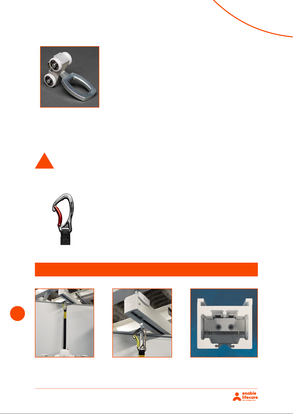
Using the Reacher Bar
Magnetic Connection of the Hand Control to the Nimble204
Open carabiner to attach in
slot of the Reacher Bar.
Raise the Reacher Bar to
the trolley.
Slide the top hook
through the trolley.
Lift is securely hooked
onto the trolley. The
Reacher Bar remains in
position.
Closed carabiner attached to latch of
the Reacher Bar.
Magnetic hand control for quick attachment to the
Nimble204.
!Do not place the hand control within 6” of
a pacemaker. Patients with pacemakers
must follow the instructions provided
by their physician and pacemaker
manufacturer.

Nimble204 12
Operating the Nimble204
Charging the Nimble204
The Nimble204 is switched on automatically
when a button on the hand control is pressed. The
Nimble204 switches o automatically after three
minutes without activation.
The charger plugs in into the port on the Nimble204.
The batteries should be charged on a regular basis. It is recommended that the lift be left on charge
when not in operation, and at the end of each day. This will maximize the life cycle of the batteries.
The Nimble204 may remain connected to the charger indefinitely since the charger has a built-in
regulator, eliminating the danger of overcharging.
As a general rule, it is recommended that the lift be raised to a height that will not interfere with
anything or anyone while the lift is not in use.
UP button
DO W N button
WARNING
WARNING
Do not drain the batteries excessively. This will dramatically
reduce the lifespan of the batteries. If the battery level is
critically low (see LED and Buzzer Functions section), be
sure to recharge the battery as soon as possible.
Charge the batteries to full and turn the lift o before
storing. Recharge the lift every three months while the lift
is in storage.
!
!
Nimble204 13
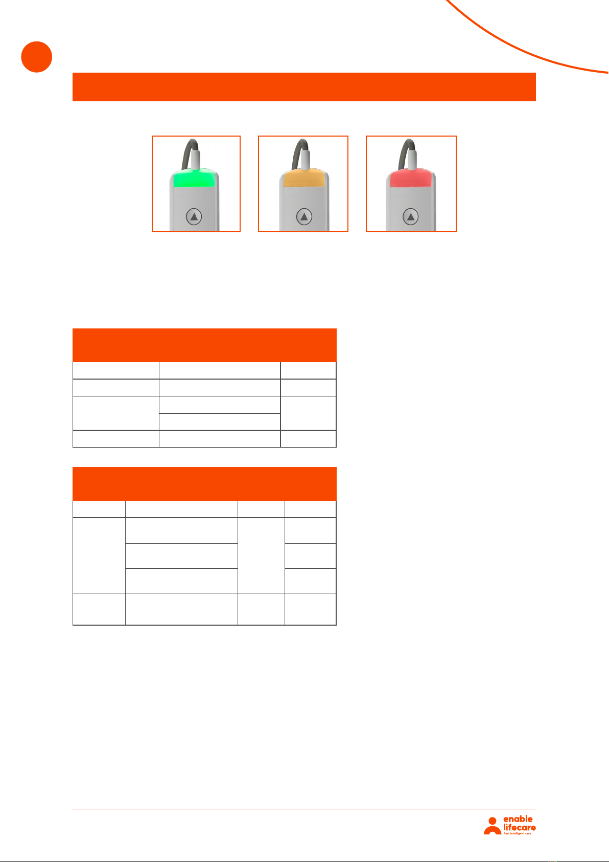
LED and Buzzer Functions
LED INDICATORS
WAKING UP A LIFT AFTER CHARGING
STATUS 1:
STATUS 2:
STATUS 3:
GREEN AMBER RED
When waking the lift from the sleep state, there will be a sequence of three LED statuses before the
lift goes back to sleep. The LED color indications will dier slightly between waking the lift while
charging and while not charging. See the table below for details.
Will always show green when the lift
wakes up for four seconds.
Will be amber for four seconds to
confirm that it is currently charging.
a. If the light remains green, this means
the lift is on battery power and not
being charged.
Shows the current battery level.
a. For a lift on charge, the light will
change from amber to green after
four seconds to indicate lift is at full
charge. Otherwise, the amber light
will remain for three minutes after
inactivity before the lift goes back to
sleep.
b. For a lift on battery power, the light
will remain green for one minute if the
battery level is acceptable. If battery
level is low, the LED will change from
green to amber after nine seconds
and blink amber once per second.
If battery level is critical, the LED
will change from green to solid red
after nine seconds, beeping once
every three seconds. These states
will remain until the lift goes back
to a sleep state after one minute of
inactivity.
LED Status’ While Lift is Charging
LED Color Duration
Wake GREEN 4 secs
Charging indicator AMBER 4 secs
In use/idle
GREEN (at full charge)
3 mins
AMBER (low battery level)
Sleep (if inactive) O n/a
LED Status’ While Lift is on Battery Power
LED Color Duration Beeping
Wake GREEN 10 secs None
In use/idle
Continuous solid GREEN
(at full charge)
1 mins
None
Blinking AMBER 1x/s
(low battery level) None
Continuous solid RED
(critical battery level) 1x/3s
Sleep
(if
inactive)
O n/a n/a

Nimble204 14
LED and Buzzer Functions
Emergency Stop
OTHER ERROR CODES
Error Codes
Battery not plugged in/No temperature sensor detected Blinking red (3x/s, 1s o), beeping 1x/5s
Over capacity Blinking red (2x/s), continuous beep
Charging error: Battery over temperature/Sensor Error Blinking red (2x/s), beeping 1x/5s
Brake end of life Blinking red (4x/s,1s o), beeping 1x/5s
Maintenance alarm Blinking green (2x/s)
Maintenance alarm:
After 1,001 lifts, the LED will flash green. To reset, press buttons in the following sequence: Up,
Down, Up, Down, then hold both buttons for 10 seconds. If successful, the LED turns red, green and
amber. The buzzer will beep three times. Note: Reset can be performed at any time, not just after
the 1000th lift.
The Nimble204 has an Emergency Stop feature that allows the operator to completely shut o the
power to the lift in the event of an emergency. This can be completed by pressing down on the “O”
indicator on the red switch located on the back of the unit. To re-activate the lift, simply press down
on the “I” indicator on the same red switch.
Nimble204 15
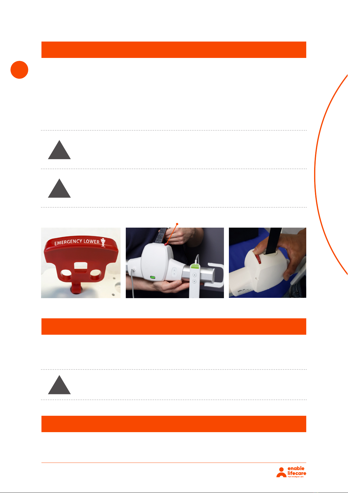
Emergency Lowering
In the event that the DOWN button on the hand control does not function, or in power failure
situations, the patient may be lowered by pressing and holding down the RED emergency lowering
button located on the top of the lift. Continue to press down until the patient is safely lowered to the
desired position. The lift will beep as you continue to press down on the red button and will continue
beeping until the button is released after the desired lowering has been achieved.
NOTE: The emergency lowering button does not provide a raising function. The failure of any of the
lowering devices should be reported to Enable Lifecare.
WARNING
WARNING
WARNING
In an event of emergency hen normal lowering system of the
lift malfunctions and the “emergency lowering” function is
used, the lift must be examined by a qualified lift technician
before re-use.
Do not press the red button forcefully. For assistance after
an emergency contact Amico Service: amo-service@amico.
com or 1.877.462.6426
Do not attempt to use the lift while using manual lowering.
!
!
!
Emergency Lowering Button
Continue to press down until the patient
is safely lowered to the desired position.
Manual Emergency Lowering
Overspeed Cam
The manual emergency lowering and raising feature should only be used if all other controls fail. A
proper safety ladder or stool may be required. Use a 3/16” or 2.5 mm Allen key to rotate the motor in
the up or down direction.
The Overspeed Cam brake is made of a metal bar fixed to the drum. In case of gear or motor breakage,
the centrifugal force created will block the bar against the frame.

Nimble204
The exterior of the Nimble204 should only be cleaned, disinfected using the recommended cleaning
agents shown below. Damp a cloth with the cleaning agent and wipe down the entire exterior of the
lift. Other chemicals and/or liquids not listed should not be used to clean and disinfect this lift.
Recommended cleaning agents:
• CaviWipes
• Clorox Healthcare Professional Disinfecting Bleach Wipes
• Dispatch Hospital Cleaner Disinfectant Towels With Bleach
• Oxivir Tb Disinfectant Wipes
• Sani-Cloth Super Germicidal Disposable Wipes
• tB Minuteman NEX GEN
• Virocidin-X
• Virox-5
• Virox Accel Tb
Clean the inside of the tracks every 4 months using a damp cloth to ensure a smooth rolling surface
for the trolley.
Should problems arise with the use of the Nimble204, review the following chart. Find the fault and
complete the recommended solution. If the fault is not found and or/the solution does not correct the
problem contact Enable Lifecare.
16
Cleaning and Disinfection
Troubleshooting
WARNING
Take great care to ensure that no liquids get inside the
Nimble204. The lift is not drip proof or water tight. Failure to
protect the lift from liquids may result in damage to the lift
and may cause personal injury.
!
Fault Recommended Solution
The Nimble204 beeps once every 3 seconds while in
use. The lift only goes down but not in the upwards
direction.
The batteries are low and the lift should be charged.
The Nimble204 cannot lift.
If the load is in excess of the safe working load
the Nimble204 will not work due to over-current
protection.
The batteries are always dead after a few charges. Replace the batteries as they may be at the end of
their service life.
The Nimble204 does not operate when you press the
buttons on the hand control. Check that the emergency button is in the on position.
The lift does not go up. There may be a twist in the lift strap.

Nimble204 17
Prior to using the Nimble204, the inspections should be conducted per the following schedule:
Inspection and Maintenance
Item Before Use Every Month Annual
The Nimble204 beeps once every 3 seconds. ○
Ensure that endstops are installed ○
Inspect strap for wear or fraying ○
Ensure Batteries are charged ○
Inspect hooks for damage or sharp edges ○
Inspect the wheels in the portable trolley.
Replace if damaged. ○
Sling
Check all straps for wear or fraying ○
Inspect the sling for any damage in the fabric ○
Ensure there are no loose threads in the stitching ○
Maintenance by a certified technician
Check the strap and replace only if frayed or damaged ○
Inspect the gearbox for any unusual noises ○
Inspect the hook components for any signs of damage ○
Inspect the gears for any broken or worn teeth ○
** Verify the overspeed cam is operating freely ○
Check emergency stop button ○
** Check emergency lowering device ○
*Annual load test with SWL (maximum safe working load) ○
Ensure the endstops are installed ○
*Reapply grease to the gears ○
* In accordance to the ISO 10535 Standard “Hoists for the transfer of disabled persons – Requirements
and test methods” an inspection should be performed on the Nimble204 at least once a year. This
inspection should be performed by a qualified technician and should include a working load test of
one (1) lifting cycle with the maximum load.
*Re-apply grease to the gears using the Amico certified grease. Can be bought from Amico.
** These two functions must be checked by a qualified technician to ensure the essential performance
of the Nimble204.
WARNING Do not operate the Nimble204 until any issues discovered
during the inspection have been addressed by a certain
technician.
!

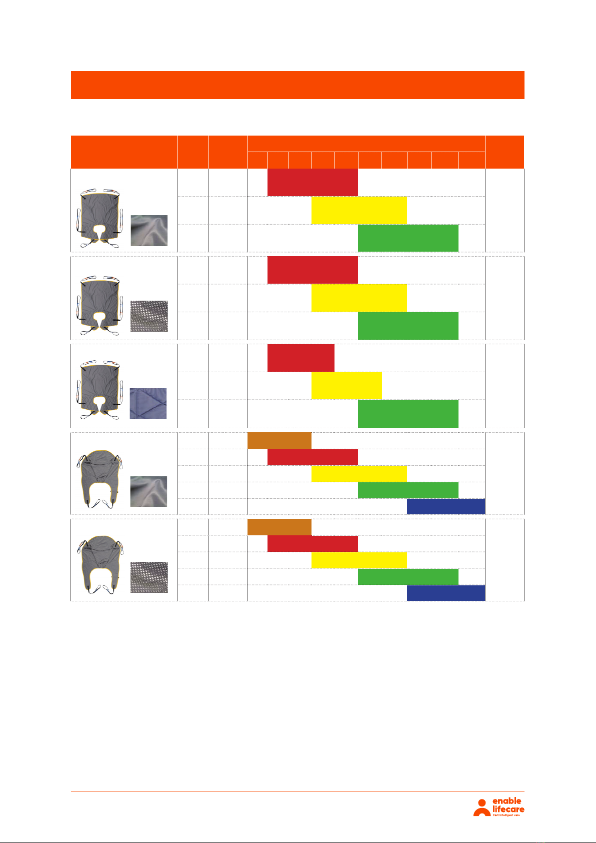
Nimble204
SLING SIZE COLOR
RECOMMENDED WEIGHT RANGE (kg) FIM
SCORE
15 34 45 57 68 80 90 125 136 227
XS Brown LG6245
2 & 3
SRed LG6246
MYellow LG6247
LGreen LG6248
XL Blue LG6249
XS Brown LG6235
2 & 3
SRed LG6236
MYellow LG6237
LGreen LG6238
XL Blue LG6239
SRed LG6047
1 & 2
MYellow LG6059
LGreen LG6071
XL Blue LG6079
XS Brown LG6538
1 & 2
SRed LG6051
MYellow LG6063
LGreen LG6075
XL Blue LG6540
SRed LG6043
1 & 2
MYellow LG6055
LGreen LG6067
Oxford®Style Sling Color/Size Chart - Standard Size
LOOP SLINGS
Recommended weight range should only be used as a guideline
as other factors can aect sizing.
Access
Access, Head Support
Quickfit
Quickfit
Quickfit
LIFT TYPES SPREADER BAR SLING SWL
Advance
Elara
Presence
Midi 180
Stature Loop 227 kg
Material:
Padded
Material:
Padded
Material:
Padded
Material:
Mesh
Material:
Polyester
4
18
Nimble204 Accessories
Nimble204 19
Nimble204 Accessories
XS Brown LG6117
1 & 2
SRed LG5030
MYellow LG5032
LGreen LG5034
XL Blue LG6125
XS Brown LG6127
1 & 2
SRed LG6129
MYellow LG6131
LGreen LG6133
XL Blue LG6135
Full Back
Full Back
Material:
Mesh
Material:
Polyester
SLING SIZE COLOR
RECOMMENDED WEIGHT RANGE (kg) FIM
SCORE
15 34 45 57 68 80 90 125 136 227
SRed LG5010
1 & 2MYellow LG5014
LGreen LG5018
SRed LG5012
1 & 2MYellow LG5016
LGreen LG5020
SRed LG6095
1 & 2
MYellow LG6101
LGreen LG6107
Quickfit Deluxe
Quickfit Deluxe
Quickfit Deluxe
Material:
Polyester
Material:
Mesh
Material:
Padded
*All slings on this page may be used for amputees
6

Nimble204 20
Nimble Gantry System
Nimble Free Standing Gantry
The Nimble Gantry is a portable freestanding lift stand which, in combination with a rail and a ceiling
lift motor, functions as a stationary lift system. Gantry is an ideal solution for occasional lifting needs
in a specific location, or where it is not possible to install a permanent rail system on the ceiling.
Features:
• Sturdy and stable construction
• Made of aluminium
• Easy to assemble and disassemble
• Easy to move and store
• For use with both fixed and portable ceiling lift motors
• Weight capacity 204 kg
• Set up in 5 minutes
• Width: 2.34 m
• Height 2.11 m
PRODUCT
CODE:
HA1070
Environmental Conditions
Operation
MINIMUM MAXIMUM
Temperature +10°C +40°C
Relative atmospheric humidity 30% 75%
Air pressure 700 hPa 1060 hPa
Transport/Storage
MINIMUM MAXIMUM
Temperature -10°C +50°C
Relative atmospheric humidity 20% 90%
Air pressure 700 hPa 1060 hPa
NOTE: It is recommended that the lift be brought back to an area kept at room temperature between
uses. For example after transport in a vehicle do not leave the lift in the trunk or backseat.
Also, try to keep the lift from staying in rooms with a metallic roof where temperatures may increase
the allowable operating temperature.
Table of contents
Other Enable Lifecare Medical Equipment manuals


