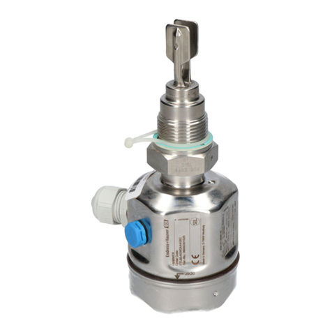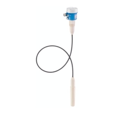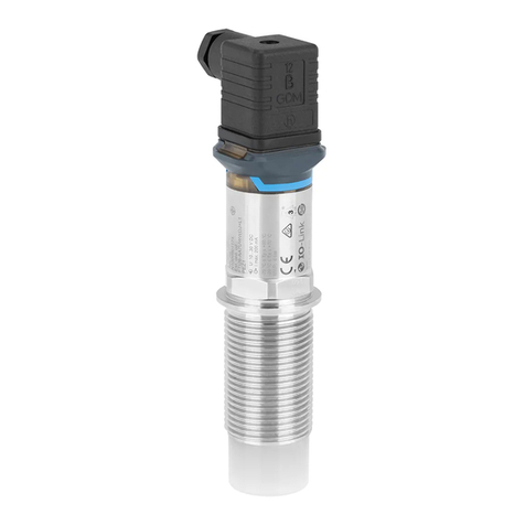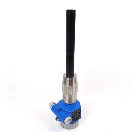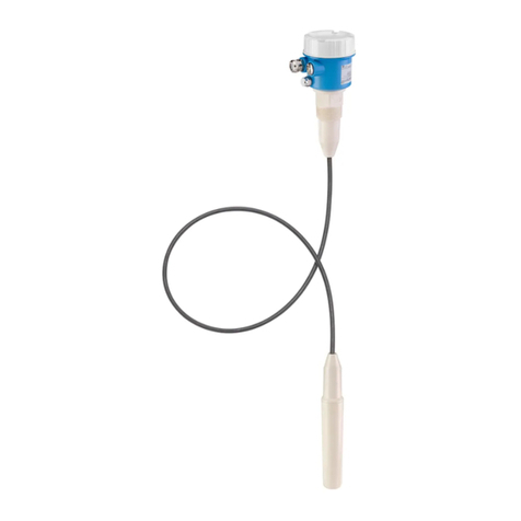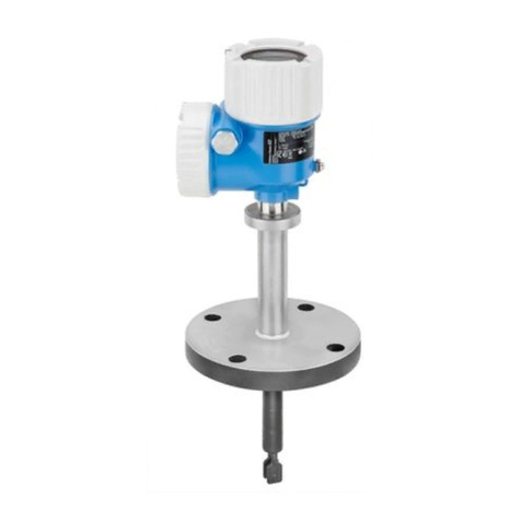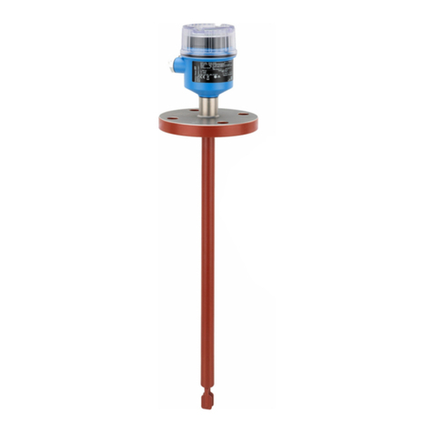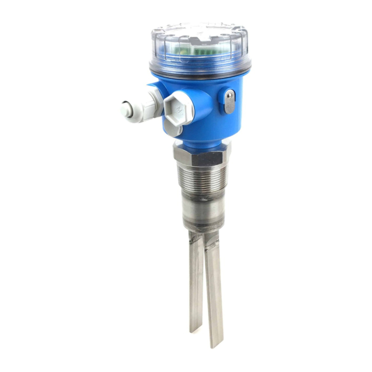
Liquiphant FTL64
2 Endress+Hauser
Table of contents
About this document ........................ 4
Symbols ................................... 4
Function and system design ................... 5
point level detection ........................... 5
Measuring principle ........................... 5
Measuring system ............................ 5
Dependability ............................... 5
Input .................................... 5
Measured variable ............................ 5
Measuring range .............................. 5
Output ................................... 6
Output and input variants ........................ 6
Output signal ................................ 6
Ex connection data ............................ 6
2-wire AC (electronic insert FEL61) ............. 7
Supply voltage ............................... 7
Power consumption ............................ 7
Current consumption ........................... 7
Connectable load .............................. 7
Behavior of output signal ........................ 7
Terminal assignment ........................... 7
Behavior of switch output and signaling .............. 8
3-wire DC-PNP (electronic insert FEL62) ......... 9
Supply voltage ............................... 9
Power consumption ............................ 9
Current consumption ........................... 9
Load current ................................. 9
Capacitance load .............................. 9
Residual current .............................. 9
Residual voltage .............................. 9
Behavior of output signal ........................ 9
Terminal assignment ........................... 9
Behavior of switch output and signaling ............. 10
Universal current connection with relay output
(electronic insert FEL64) .................... 11
Supply voltage .............................. 11
Power consumption ........................... 11
Connectable load ............................. 11
Behavior of output signal ....................... 11
Terminal assignment .......................... 12
Behavior of switch output and signaling ............. 12
DC connection, relay output (electronic insert
FEL64 DC) ................................ 13
Supply voltage .............................. 13
Power consumption ........................... 13
Connectable load ............................. 13
Behavior of output signal ....................... 13
Terminal assignment .......................... 13
Behavior of switch output and signaling ............. 14
PFM output (electronic insert FEL67) ........... 14
Supply voltage .............................. 14
Power consumption ........................... 14
Behavior of output signal ....................... 14
Terminal assignment .......................... 15
Connection cable ............................. 15
Behavior of switch output and signaling ............. 16
2-wire NAMUR > 2.2 mA/ < 1.0 mA (electronic
insert FEL68) ............................. 16
Supply voltage .............................. 16
Power consumption ........................... 16
Behavior of output signal ....................... 16
Terminal assignment .......................... 17
Behavior of switch output and signaling ............. 17
LED module VU120 (optional) ................ 18
Supply voltage .............................. 18
Power consumption ........................... 18
Current consumption .......................... 18
Signaling of operational status .................... 18
Bluetooth module and Heartbeat Technology .... 18
Bluetooth module VU121 (optional) ................ 18
Heartbeat Technology ......................... 19
Performance characteristics .................. 19
Reference operating conditions ................... 19
Measured error ............................. 20
Hysteresis ................................. 20
Non-repeatability ............................ 20
Influence of the process temperature ............... 20
Influence of the process pressure .................. 20
Installation ............................... 20
Mounting location, orientation ................... 20
Installation instructions ........................ 21
Installing in pipes ............................ 23
Screwing in the device ......................... 23
Align the cable entry .......................... 24
Special mounting instructions .................... 24
Environment .............................. 24
Ambient temperature range ..................... 24
Storage temperature .......................... 25
Humidity .................................. 26
Operating altitude ............................ 26
Climate class ............................... 26
Degree of protection .......................... 26
Vibration resistance .......................... 26
Shock resistance ............................. 26
Mechanical load ............................. 26
Electromagnetic compatibility .................... 26
Process .................................. 26
Process temperature range ...................... 26
