Enel X JuicePump User manual

Site Installation Manual

TRI125.INS.018.4
Page 2 of 35
Contents
1Overview..................................................................................................................................3
1.1 Purpose of this document.........................................................................................................3
1.2 Disclaimer and warranty...........................................................................................................3
1.3 Acronyms and abbreviations....................................................................................................3
1.4 Identifying symbols...................................................................................................................4
1.5 Specifications ...........................................................................................................................5
1.6 IMPORTANT SAFETY INSTRUCTIONS.................................................................................6
1.7 Grounding...............................................................................................................................10
1.8 Wiring .....................................................................................................................................10
1.9 Ratings ...................................................................................................................................11
1.10 Usage limitations....................................................................................................................11
1.11 Installation safety considerations ...........................................................................................12
1.12 References and related documents .......................................................................................12
2Site plan.................................................................................................................................13
2.1 Block diagram.........................................................................................................................13
2.2 Layout.....................................................................................................................................14
3Resources .............................................................................................................................15
3.1 Tools and consumables .........................................................................................................15
3.2 Heavy equipment ...................................................................................................................16
3.3 Torques utilized during installation.........................................................................................16
4Installation.............................................................................................................................17
4.1 Conduit and cabling................................................................................................................17
4.2 Upstream protection...............................................................................................................17
4.3 Earthworks..............................................................................................................................18
4.4 HPC equipment storage recommendations and conditions...................................................18
4.5 High-power electrical connections..........................................................................................20
4.6 Isolated power unit installation ...............................................................................................21
4.7 UU installation ........................................................................................................................29
5Site installation handover....................................................................................................34
5.1 Pre-checks..............................................................................................................................34
5.2 Polarity, cross-wire, and bolted short test ..............................................................................34

TRI125.INS.018.4
Page 3 of 35
1 Overview
1.1 Purpose of this document
The purpose of this document is to provide qualified electrical engineers and manufacturer-
certified installers with an outline of the steps required to install a JuicePump 175-S high-
power charging 175 kW site.
This document is for both the single and dual cable variants of the JuicePump 175-S.
Note: The images used in this document are of the dual cable variant.
1.2 Disclaimer and warranty
This manual sets out the manufacturer’s understanding of best-practice methodologies and
its requirements for installation of the JuicePump 175-S.
The manufacturer encourages all owners of its products to consult a qualified engineering
consultancy firm to provide independent advice on the methodologies set out in this manual
and site design requirement, including in relation to applicable regulatory and statutory
requirements. All site designs must be signed off on by a professional engineer.
The manufacturer accepts no liability for any loss caused, whether due to negligence or
otherwise arising from the strict adherence to the requirements set out in this manual in
contravention of local regulatory and legal requirements.
It is an express condition of the manufacturer’s warranty that:
•The requirements set out in this manual are adhered to (subject to local regulatory and
legal requirements) when installing the JuicePump 175-S; and
•The installation is conducted by a manufacturer-certified technician who has completed
the manufacturer’s installation training course for the JuicePump 175-S.
1.3 Acronyms and abbreviations
Acronym/abbreviation
Definition
CID
Component Identifier
DIN
Deutsches Institut für Normung
The German national standards organization.
DIN rail is a metal rail of a standard type widely used for mounting
circuit breakers. DIN Connectors and DIN wiring
DMM
Digital Multimeter
HMI
Human Machine Interface
HPC
High Powered Charging
IMI
Insulation Monitoring Interrupter
IP
Internet Protocol
IPU
Isolated Power Unit.
JuicePump175-S Solution
TRI125-175 - JuicePump 175 kW RT 175-S Solution
Comprised of a single IPU and a pair of UU.
LV
Low Voltage
LVR Kit
Low Voltage Rescue Kit
PE
Protective Earth
TRI125.INS.018.4
Page 4 of 35
Acronym/abbreviation
Definition
PCB
Power Circuit Board
PU
Power Unit
UU
User Unit
UV
Undervoltage
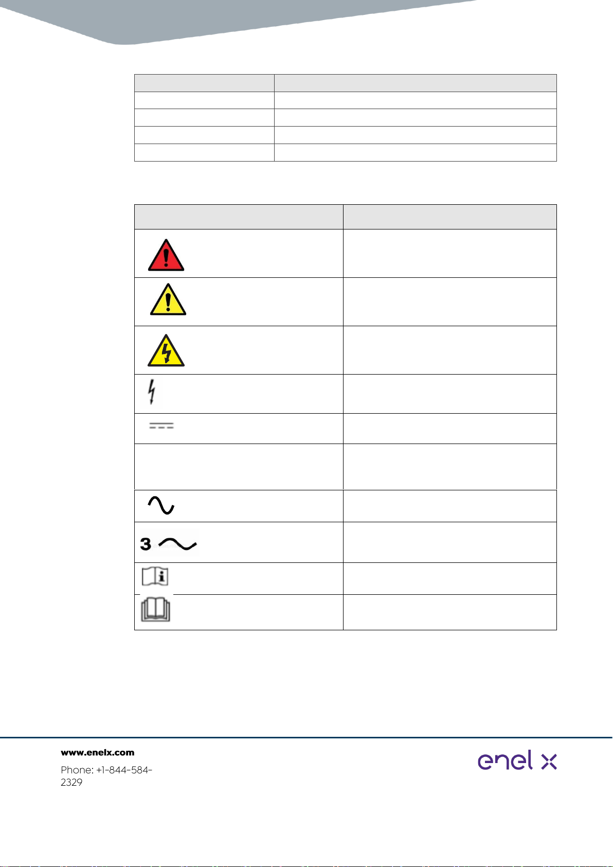
1.4 Identifying symbols
Symbol
Meaning
CRITICAL
CAUTION
RISK OF ELECTRIC SHOCK
Dangerous voltage
Direct Current (DC)
ø
Phase Symbol
Alternating Current Supply Symbol
3-Phase Alternating Supply (no neutral
connection)
Operators Manual; Operating Installations
Read Operators Manual

TRI125.INS.018.4
Page 5 of 35
1.5 Specifications
Unit
Specifications
LV Distribution Board
•185 kVA Output per charger
•400 V/300 A 50 Hz, 480 V/250 A 60 Hz, 600 V/200 A 60 Hz
•UL-listed circuit breakers with optional under-voltage relay
•Maximum available fault current of 18 kA (current limiting fuses or
current limiting circuit breakers may be required to maintain limit
of 18 kA)
•Residual current monitoring device of time delay type (optional)
Isolated Power Unit
•1 x 185 kVA double insulated safety isolation transformer
•1 x 175 kW AC/DC converter with AC contactors
•Integrated Communications Unit, Dual 4G SIM
•800 kg
User Unit
•1 x 175 kW 350 A DC/DC converter (CCS/CHAdeMO)
•260 kg
TRI125.INS.018.4
Page 6 of 35
1.6 IMPORTANT SAFETY INSTRUCTIONS
SAVE THESE INSTRUCTIONS
The instructions must be followed during installation, operation, and maintenance of the unit.
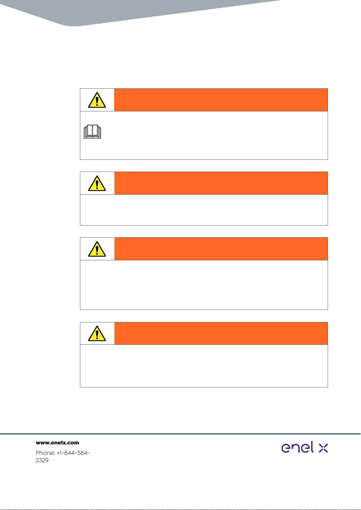
Warning!
These instructions must be read prior to installation of the unit.
This manual contains important instructions for the JuicePump 175-S 175 kW
DC electric vehicle fast charger
The instructions shall be followed during installation, operation, and maintenance of the
unit.
Warning!
Danger due to installation location
Installation shall not be made in a commercial garage (repair facility) or closer than
20 feet / 6096 mm of an outdoor motor fuel dispensing device.
Warning!
Danger due to incorrect installation or servicing
The installation must be conducted by a manufacturer Certified technician who has
completed the manufacturer’s installation training course for the JuicePump 175-S.
The JuicePump 175-S fast charger system must be installed and serviced only by
qualified electrical personnel (subject to local regulatory and legal requirements.)
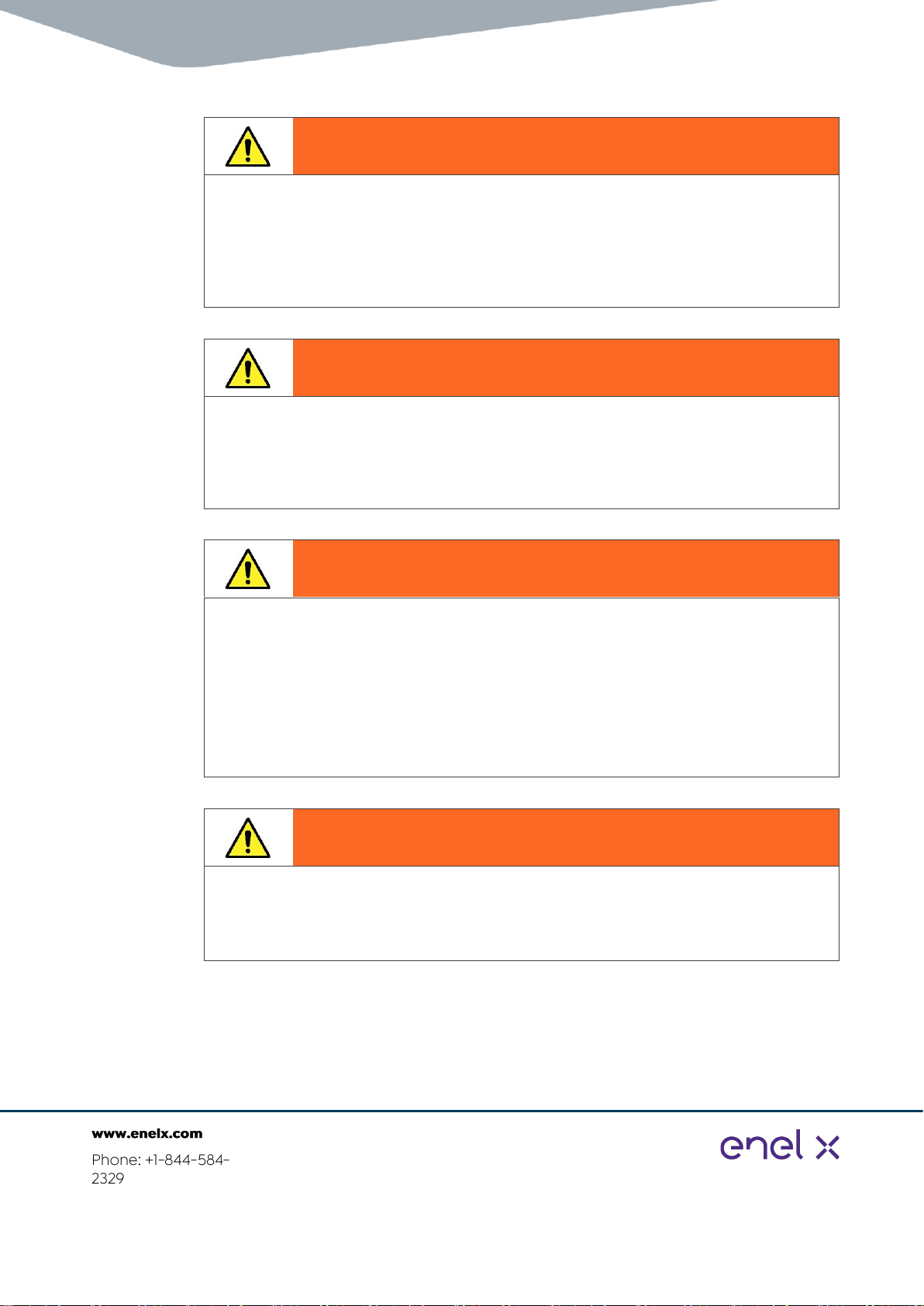
Caution!
Danger due to incorrectly tightened terminals
This may result in heat damage to the charger, which may lead to fire.
When connecting AC and DC cables, ensure that all the terminals are tightened to the
specified torque.

TRI125.INS.018.4
Page 7 of 35
Caution!
Risk of fire
To reduce the risk of fire, connect only to a circuit provided with 320 A maximum branch
circuit overcurrent protection in accordance with the National Electrical Code, ANSI/NFPA
70.
Warning!
Danger when lifting units
The rain hood and spacers are not appropriately rated for lifting the unit. Failure to remove
them may cause damage to the IPU and/or serious accident.
NEVER lift the IPU in a horizontal position if the primary transformer has been installed.
The cabinet is not rated for this.
Warning!
Danger due to inadequate ground conductor connection
This can result in serious injury and damage to property.
•This document provides guidelines for earth connections for the charger and the
wiring of the system.
•Connections to the battery charger shall comply with all local codes and ordinances.
Warning!
Cord extensions or adaptors could cause over heating serious injury or fire
•Cord extension sets or second cable assemblies shall not be used in addition to the
cable assembly for the connection of the vehicle to the charger.
•Adaptors shall not be used to connect a vehicle connector to a vehicle inlet.
Warning!
Incorrect fusing or input over current device can compromise the electrical safety of
this charger and could result in serious injury or fire
Available short-circuit fault current for the RT 175-S must not exceed 18 kA. This means
that a current-limiting fuse or circuit breaker may be required in locations where site fault
current availability exceeds this value.

TRI125.INS.018.4
Page 8 of 35
TRI125.INS.018.4
Page 9 of 35
Warning!
Conduit and cabling
Prior to installation of the piping and wiring, a professional review of local requirements
must be performed to ensure that laws and regulations are adhered to. As a result, it may
be required to deviate from the requirements of this documentation.
Note: Deviations from these instructions must not reduce the effective safety and integrity
of the installation and the product.
Warning!
Piping and wiring
Prior to installation of the piping and wiring, a professional review of local requirements
must be performed to ensure that laws and regulations are adhered to. As a result, it may
be necessary to deviate from the cable lug sizes (and corresponding cable sizes)
referenced in this manual.
Warning!
Earthing electrode
•For EMC compliance, it is important that a local earthing electrode is used to bond the
chassis of the IPU directly to ground. This may be in the form of an earth stake, or if
available, can be bonded to pre-existing buried earth structures.
•Prior to installation of the unit, a professional review of local lightning protection
requirements must be performed to ensure that laws and regulations are adhered to.
As a result, it may be necessary to install additional earthing electrodes for outdoor
installations.
Warning!
Be aware that lifting heavy loads that are inadequately secured, could damage the
product and cause serious injury
Be careful as the unit may swing. A second operator may be required to control the UU
lift.

TRI125.INS.018.4
Page 10 of 35
1.7 Grounding
This unit must be connected to a grounded, metal, permanent wiring system, and an
equipment-grounding conductor must be run with circuit conductors and connected to
equipment-grounding terminal or lead on the electric vehicle charger.
•Connections to the battery charger shall comply with all local codes and ordinances.
•Electrical Connections to the RT 175-S PU and UU and interconnection cables and
conduit shall comply with all local codes and ordinances. Including all connections to
grounding conductor and earthing electrodes.
1.8 Wiring
Power and protective earth (PE) Conductor ratings:
•DC copper 95 mm2 (cross section)
•V90 class, rated to operate at 90°C.
The manufacturer recommends the use of copper cables. Refer to the following JuicePump
175-S document for reference specifications - TRI125.INS.016 ENEL X 175-S Piping and
Cabling.
Take care to observe local regulations regarding wiring different circuits in the same conduit,
including the Ethernet link if used.
In general, all conductors occupying the same conduit shall have an insulation rating equal
to at least the maximum circuit voltage applied to any conductor within the conduit.
Warning!
Danger due to inadequate ground conductor connection
This can result in serious injury and damage to property.
•This document provides guidelines for earth connections for the charger and the
wiring of the system.
•Connections to the battery charger shall comply with all local codes and ordinances.

TRI125.INS.018.4
Page 11 of 35
1.9 Ratings
0B0BInput
User Unit
950 VDC 190 A
1ø,240 VAC, 3 A, 50/60 Hz
The JuicePump user unit must be
connected to a circuit provided with
appropriate over-current protection in
accordance with the national, regional, and
local regulations in the country of
installation.
1B1B1BInput
Power Unit:
400 VAC 3~, 50 Hz, 270 A, or
480 VAC 3~, 60 Hz, 225 A, or
600 VAC 3~, 60 Hz, 200 A
For more information refer to the following
datasheet:
•TRI125.DTA.009 JuicePump RT175-S
Datasheet (covers UU and PU)
Note: IPU ratings are region dependent;
ensure you have the correct equipment for
your region.
2B2B2BTorque Settings
See section 3.3. Torques utilized during
installation.
3B3B3BWeather Rating
PU IP55, NEMA 3R
UU IP65, NEMA 3R
1.10 Usage limitations
Warning!
Cord extensions or adaptors could cause over-heating, serious injury, or fire
•Cord extension sets or second cable assemblies shall not be used in addition to the
cable assembly for the connection of the vehicle to the charger.
•Adaptors shall not be used to connect a vehicle connector to a vehicle inlet.

TRI125.INS.018.4
Page 12 of 35
1.11 Installation safety considerations
•First Aid Kit
•LVRK
•Defibrillator
•Never walk under suspended loads
•Site shall never be worked on while electrically live. Before any duty, ensure LV
distribution board circuit breakers are isolated and locked out.
•Fencing and exclusion zones, authorization from the local authorities
•Exclusion zones when lifting hardware
•Shelter from weather (sun, wind, dust, and rain)
•Second person in the event of an accident
1.12 References and related documents
•TRI125.INS.016 JuicePump RT175-S Piping and Cabling
•TRI125.INS.019 JuicePump RT175-S User Unit Installation Manual
•TRI125.INS.033 JuicePump RT175-S Maintenance Manual
•TRI125.DTA.009 JuicePump RT175-S Datasheet (covers UU and PU)
•TRI125.CHK.008 JuicePump RT175-SK System Installation Checklist
TRI125.INS.018.4
Page 13 of 35
2 Site plan
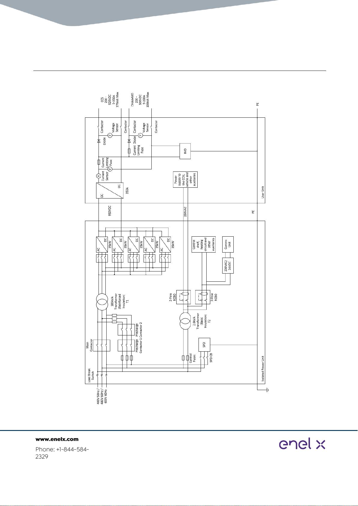
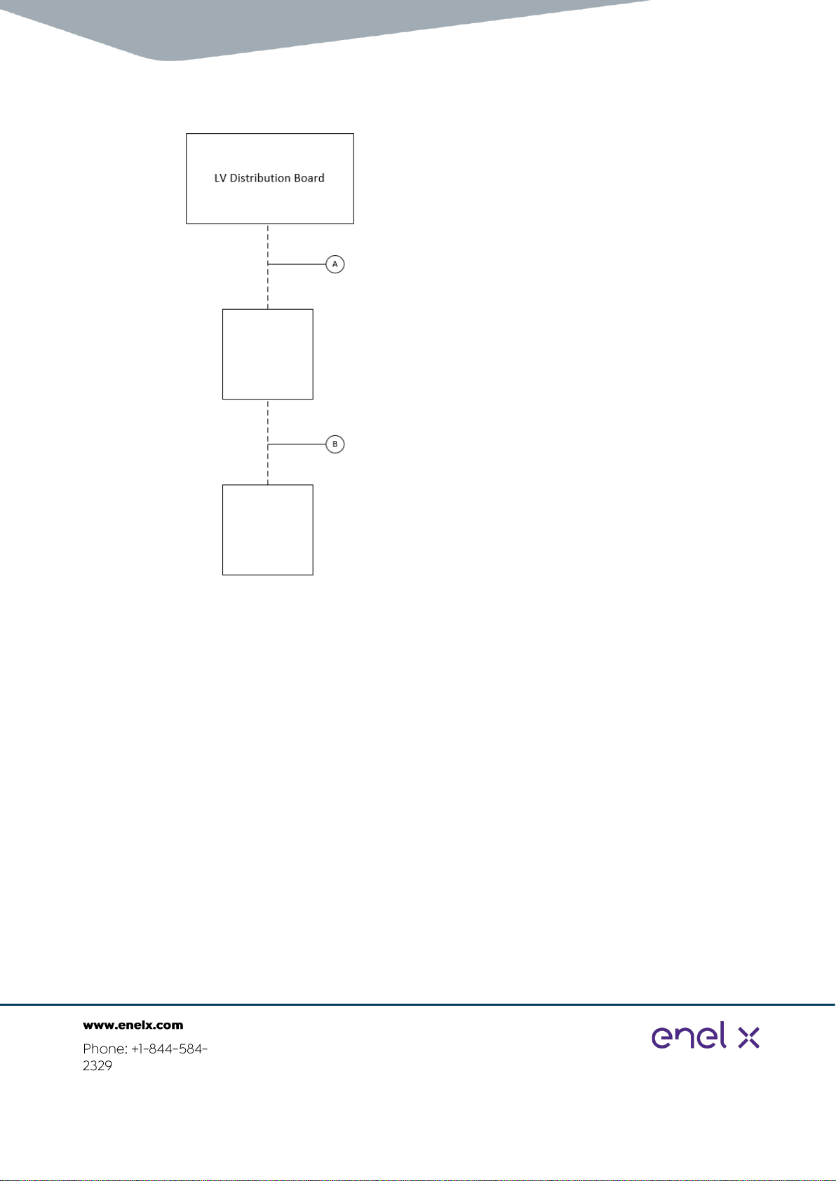
2.1 Block diagram
Figure 1: Single charger block diagram
TRI125.INS.018.4
Page 14 of 35
2.2 Layout
Figure 2: Site electrical layout
IPU
UU

TRI125.INS.018.4
Page 15 of 35
3 Resources
3.1 Tools and consumables
3.1.1 Tools
•Network termination equipment
•Electric hydraulic cable lug terminator
•100 m hook-up wire
•4 x 1 T (minimum) rated lifting straps
•Rags
•Electric caulking gun
•Drill
•Torque wrench
•Step ladder
•Table
•Chair
•General tools:
•Spanners
•Shifters
•Socket Set >24 mm
•Screwdrivers
•Side cutters
•Hex keys
•Knife
•Multi-grip pliers
3.1.2 Consumables
Ensure that the appropriately-sized cable termination lugs for the AC and DC installation
wiring are procured, as well as the required heat-shrink to demark three-phase AC cabling,
high-powered DC cables, and protective earth cables.
Glands for customer cabling to and from the IPU must also be installer supplied. Glands for
the user unit are supplied in the installation kit for that region.
CID
Description
QTY
12942 OR
12943
RT 175-S Installation Kit (CID is region dependent).
Note: Does not contain any DIN standard lugs.
-
5542
UL Listed Cable Tie, Yellow, 100 x2.5 mm, PK100
200
6234
UL Listed Cable Tie, 94 V-2, 292 mm x 4.8 mm Black, Panduit, PK100
1
8405
Cable Ties, Black, 450 x 8 mm, Heavy Duty, 100 pack
1
9543
NOFIRNO(R) Cable Sealant
-
9127
Category 6a 10 G Shielded Keystone Slimline Jack Toolless 180° IDC
2
9416
Category 6a S/FTP LSZH 1.5 m RJ45-RJ45 Network Cable: Blue
2
9565
Molex 44915 Series Number Cat6 8P8C Way Cable Mount RJ45 Modular
Plug Male
2
5792
EJCC Copper Jointing Compound
125 ml
2567
Aluminum Jointing Compound
125 ml

TRI125.INS.018.4
Page 16 of 35
Note: Due to difficulties shipping jointing compound, copper and aluminum, compound must
also be installer-supplied as needed.
3.2 Heavy equipment
•Crane –with 7 m reach, 1 T lift capacity
•Forklift
•Temporary weather shelter
3.3 Torques utilized during installation
Equipment
Thread code
Position
Torque (Nm)
UU
M5
Hatch cover
2
M8
Ground
16
M8 post hex
Outer covers
4
M10
DC
30
M12/16
Chassis mount
30/40
IPU
M10
DC
30
M10
AC, Ground
30
M12
Chassis mount
30
TRI125.INS.018.4
Page 17 of 35
4 Installation
4.1 Conduit and cabling
Refer to TRI125.INS.016 JuicePump RT 175-S Piping and Cabling.
Site electrical design must be carried out and approved by a suitably qualified professional.
Prior to commissioning, the electrical installation must be signed off as safe, complete, and
compliant to local laws and regulations.
4.2 Upstream protection
4.2.1 Device selection
Maximum sizes for the upstream electrical protective equipment supplying the RT 175-S IPU
are as described in the following table.
Electrical Network
RT 175-S Maximum
Demand
Recommended Size
Maximum Size 2
600 VAC 3 PH, 60 Hz
200 A
250 A 1
250 A
480 VAC 3 PH, 60 Hz
250 A
320 A 1
320 A
400 VAC 3 PH, 50 Hz
300 A
320 A
350 A
1Recommended sizes for North American markets are selected according to NEC article
625, accounting for the 125% rule.
2The over-current protection device rating must not exceed these values in order to maintain
primary protection for the LV transformer within the IPU.
Warning!
Incorrect fusing or input over current device can compromise the electrical safety of
this charger and could result in serious injury or fire
Available short-circuit fault current for the RT 175-S must not exceed 18 kA. This means
that a current limiting fuse or circuit breaker may be required in locations where site fault
current availability exceeds this value.
Warning!
Conduit and cabling
Prior to installation of the piping and wiring, a professional review of local requirements
must be performed to ensure that laws and regulations are adhered to. As a result, it may
be required to deviate from the requirements of this documentation.
Note: Deviations from these instructions must not reduce the effective safety and integrity
of the installation and the product.

TRI125.INS.018.4
Page 18 of 35
Caution!
Risk of fire
To reduce the risk of fire, connect only to a circuit provided with 320 A maximum branch
circuit overcurrent protection in accordance with the National Electrical Code,
ANSI/NFPA 70.
4.2.2 Optional under-voltage relay
The IPU includes pre-wired terminals to allow the optional use of an under-voltage device at
the upstream supply breaker. The pre-wired terminals supply a normally closed 230 VAC
signal to allow upstream isolation in the event of a RT 175-S safety loop trip (for example,
tilt-switch or cabinet door switch).
The use of an upstream under-voltage trip is optional, as the IPU locally isolates via the input
contactor in each of these events.
4.3 Earthworks
Ensure that earthworks and trenching is completed with respect to installation personnel
safety and applicable local and national legislation.
Ensure that all trenches are adequately roped off or barricaded to prevent accidental access
and take care with respect to trenching locations and timing to allow appropriate access to
equipment as required.
4.4 HPC equipment storage recommendations and conditions
Ensure that equipment is stored properly on site to ensure that it is protected from the
weather and not exposed to rain. Packaging may be damaged when wet.
When storing equipment:
•Stack and protect boxes inside a fenced off area of the site.
•Protect from weather conditions; store in a dry place or cover with a waterproof
tarpaulin.
•Ensure that only packing crates of similar sizes are stacked.
•Ensure a maximum height of two crates.
•Cabinets must be closed when leaving the site.

TRI125.INS.018.4
Page 19 of 35
Figure 3: Maximum stacking height of similar sized boxes.

TRI125.INS.018.4
Page 20 of 35
4.5 High-power electrical connections
It is critical that the high-power electrical connections are done correctly to ensure safe,
compliant, and warranted performance of the charging equipment.
Safety Warning!
To be installed by a certified professional
Only trained and competent electricians are authorized to perform this work.
•Ensure that the upstream power feeds are off and locked out throughout the work.
•The charging equipment must not be energized at any time during the installation. To
ensure personnel and equipment safety, power will be applied for the first time during
the commissioning phase.
•Ensure that the cables used meet the minimum requirements specified by the
manufacturer.
•Ensure that the lugs are compatible with fine-strand cable and that the crimping die is
correct for both the wire type and lug type.
•Double check lug, cable, and crimp die compatibility.
Figure 4: F type die from Klauke
•A small amount of copper jointing compound must be applied to the contact patch of all
lug-to-copper busbar connections. This inhibits corrosion at the joint to maintain a good
connection for the life of the charging system.
•Use a flat washer in contact with the top of the lug and a spring washer on top of the flat
washer for all bolted lug connections.
•Torque all connections to the specified amount, and mark the torque with a paint pen
immediately.
•Clearly label all cables. Relabel when a cable is shortened, if required.
•Mark all cables with color coded heat shrink.
•Do not cover the entire lug with heat shrink; leave one crimp mark showing so that the
correct crimping tool stamp is shown.
Other manuals for JuicePump
4
Table of contents
Other Enel X Automobile Accessories manuals


