Enel X JuicePump Guide

175 kW DC
RT
www.enelx.com
Phone: +1-844-584-2329
User Unit Installation Manual
TRI125-175-S (USA)


www.enelx.com
Phone: +1-844-584-2329
TRI125.INS.036.3
Important safety instructions................................................................................................1
Packaging, handling, & receipt...............................................................................................4
Servicing distance............................................................................................6
Cable range......................................................................................................6
Baseplate dimensions............................................................................................................7
Installation requirements & equipment.................................................................................8
Unpacking..............................................................................................................................9
Installation............................................................................................................................10
Wiring and commissioning...................................................................................................12
Ethernet port access............................................................................................................14
Closing checklist...................................................................................................................16
Contents
1www.enelx.com
Phone: +1-844-584-2329
TRI125.INS.036.3
Important safety instructions
This manual contains important
instructions for the JuicePump electric
vehicle fast charger.
Read the installation and operating
instructions before installing and
commissioning the equipment.
These instructions must be followed
during installation, operation, and
maintenance of the unit.
CAUTION
The JuicePump fast charger user unit
must be installed and serviced only by
To achieve EMC compliance, the chassis
of the JuicePump user unit must be
bonded to Earth locally at the charger.
Grounding instructions
This unit must be connected to a
grounded, metal, permanent wiring
system. An equipment-grounding conduc-
tor must be run with circuit
conductors and connected to
equipment-grounding terminal or lead on
the electric vehicle charger.
Connections to the battery charger shall
comply with all local codes and
ordinances.
Observe all pertinent national,
regional, and local safety laws and
regulations when installing and
commissioning the JuicePump fast
charger.
Identifying symbols
CRITICAL
CAUTION
RISK OF ELECTRIC SHOCK
Equipment Grounding
Conductor Symbol
ø Phase Symbol
Alternating Current Supply
Symbol
Wiring
Power and Protective Earth (PE) Conduc-
section), V90 class, rated to operate at
90°C.
The manufacturer recommends the use of
copper cables. Refer to the TRI125.
INS.016 JuicePump RT 175-S Piping and
Cabling-
tions.
Take care to observe local regulations
same conduit, including the ethernet
link if used. In general, all conductors
occupying the same conduit shall have
an insulation rating equal to at least the
conductor within the conduit.
SAVE THESE INSTRUCTIONS

2www.enelx.com
Phone: +1-844-584-2329
TRI125.INS.036.3
Warning
commercial garage (repair facility) or
closer than 6,096 mm / 20 feet of an
outdoor motor fuel dispensing device.
Input
190A
1ø, 240 VAC
3A
connected to a circuit provided with
appropriate over-current protection in
accordance with the National Electrical
Code, ANSI/NFPA 70.
Tightening torque
Wiring terminals
30 Nm / 22 lb-ft
Service hatch
2 Nm / 17.7 lb-in
Weather rating
NEMA Type 3R
Usage limitations
cable assemblies shall not be used
in addition to the cable assembly for
the connection of the vehicle to the
charger.
Adaptors shall not be used to
connect a vehicle connector to a
vehicle inlet.
Important safety instructions
SAVE THESE INSTRUCTIONS

3www.enelx.com
Phone: +1-844-584-2329
TRI125.INS.036.3
Important safety instructions
FCC Notice
Information to the User
(FCC Part 15.105)
Class A product:
NOTE:
This equipment has been tested and
found to comply with the limits for a
of the FCC rules. These limits are
designed to provide reasonable protection
against harmful interference when the
equipment is operated in a commercial
environment. This equipment generates,
uses, and can radiate radio frequency
energy and, if not installed and used in
accordance with the instruction manual,
may cause harmful interference to
radio communications. Operation of this
equipment in a residential area is likely to
cause harmful interference in which case
the user will be required to correct the
Modication warning
(FCC Part 15.21)
-
turer could void the user’s authority to
operate this equipment.
SAVE THESE INSTRUCTIONS

4www.enelx.com
Phone: +1-844-584-2329
TRI125.INS.036.3
Read these instructions carefully to
become familiar with the JuicePump user
unit packaging and handling procedures
prior to unpacking and installation.
In all cases, the JuicePump user unit
must be transported to the installation
site in its original packaging and only
unpacked at the installation site.
Installation, commissioning, and servicing
of the JuicePump user unit should only be
Materials
The JuicePump user unit is transported in
a reinforced cardboard crate.
Please respect the environment and
recycle/reuse the materials.
Storage
Store in the original packaging in a
Store in a dry location, protected from
the weather, i.e., in warehouse
conditions.
Storage temperature:
Handling
Only lift the JuicePump user unit pack-
forklift or pallet jack or with lifting straps
and engine hoist, forklift, or crane. Check
the weight on the delivery documents and
ensure the lifting apparatus used is
compatible.
Receipt
Check that the crate packaging is in
good condition and that the JuicePump
user unit is not damaged.
If there are any problems noted, make a
formal complaint to the carrier and notify
your supplier.
Packed crate weight
Crate size
Packaging, handling, & receipt

www.enelx.com
Phone: +1-844-584-2329
TRI125.INS.036.3
Site survey
installation site to determine the
and weight of the JuicePump user unit in
accordance with local regulations.
The JuicePump user unit is best
installed following the recommended site
Ground xing
fasteners.
Fasteners are not supplied, as the type
required depends on the foundation used
and must be chosen by the installer
accordingly.
user unit securely to the foundation
through the baseplate in accordance with
the “Baseplate dimensions” section.
Note: Keep the plastic inserts from the
bolts for use in the baseplate holes.
Conduit requirement
Ø 110 mm OD conduit.
When preparing the foundation,
ensure that conduit and wiring terminates
above ground according to the document
TRI125.INS.016 JuicePump RT 175-S Pip-
ing and Cabling.
Foundation requirements
have the appropriate density for the
weight of the JuicePump user unit.
foundation and level of the JuicePump
Communications
between the IPU and UU. If the UU and
(default).
4G network capability.
Category 6a STP Ethernet cable required
with a minimum length from the founda-
tion surface.
Fiber Optic Cable: OM3 Multi Mode 2 Core
For detailed wiring instructions, see
-
ing and Cabling
.

6www.enelx.com
Phone: +1-844-584-2329
TRI125.INS.036.3
Servicing distance
inches from the front and rear of the
JuicePump user unit is required to open
the front panel for servicing, as shown in
the image below.
Cable range
4300
Figure 2. Cable range
4300 mm / 169.291 inches
7www.enelx.com
Phone: +1-844-584-2329
TRI125.INS.036.3
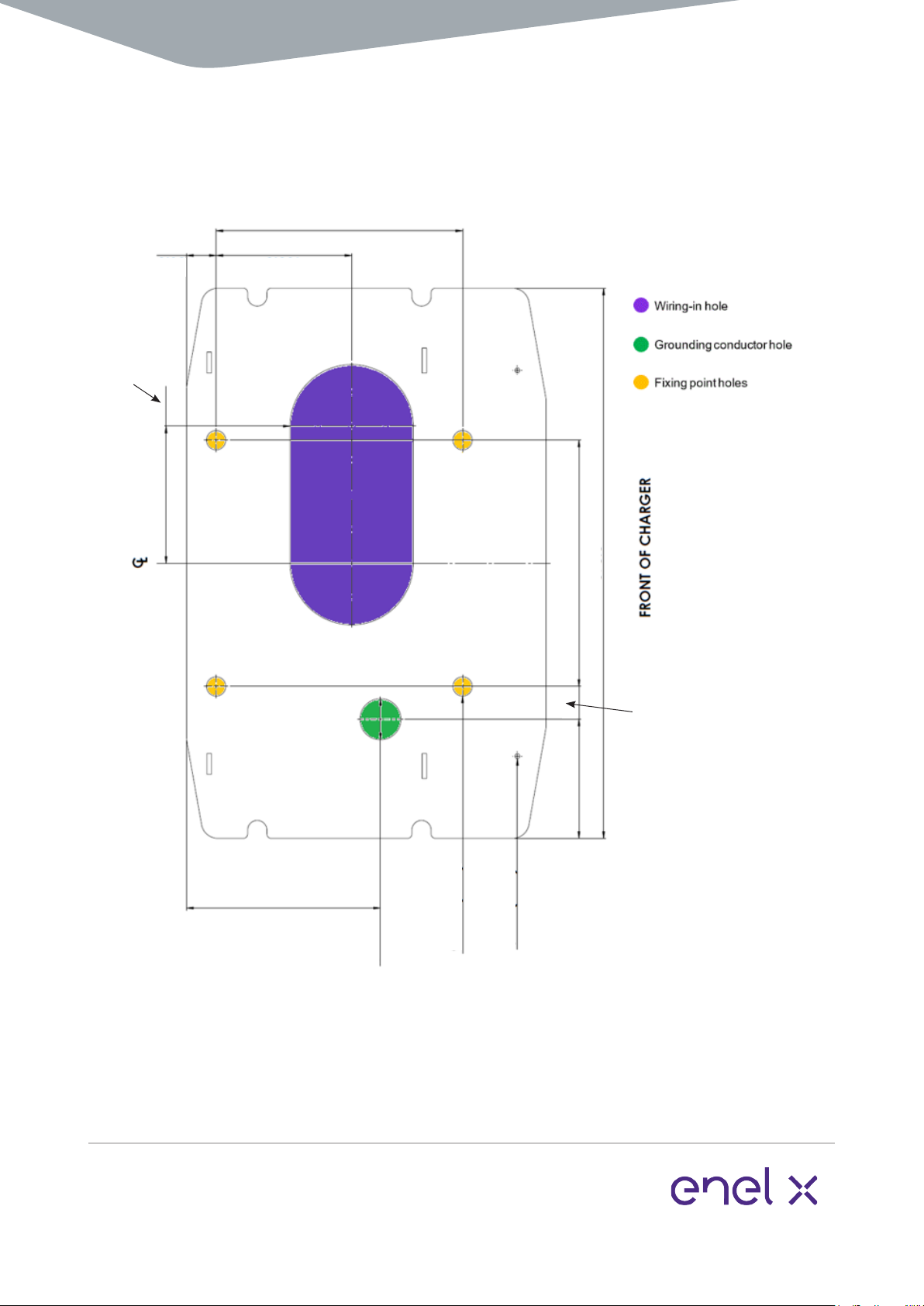
Baseplate dimensions
Note: Do not scale. All dimensions shown in millimeters (mm)/inches (in).
A mounting stencil may be supplied by the manufacturer at customer re-
quest.
300 / 11.811
36 / 1.417
236 / 9.291
670 / 26.377
300 / 11.811

8www.enelx.com
Phone: +1-844-584-2329
TRI125.INS.036.3
Installation requirements & equipment
These instructions provide a systematic
guide for installing and commissioning
the JuicePump user unit.
The JuicePump user unit must be
electrical personnel.
Observe all pertinent national, regional,
and local safety regulations when you
install and commission the JuicePump
user unit.
electronics enclosure rating, however, as
it must be opened for installation, this is
best done in dry weather or under cover
to avoid moisture and debris ingress.
The JuicePump user unit must be properly
installed, assembled, and commissioned
according to these instructions before it is
used.
Prior to installation contact your supplier
Supplied with JuicePump user
unit:
•
panels
• 4 mm Allen key to remove fasteners
on the enclosure access cover
•
•
• M10 fasteners for wiring in
•
Required equipment (not sup-
plied):
• Lifting apparatus. See the “Packag-
ing, handling, & receipt” section for
weights. Ensure lifting apparatus is
• 110 mm / 4.330 inch OD Conduit
•
for wiring installation.
•
are not supplied, as the type required
depends on the foundation used and
must be chosen by the installer
accordingly.
• Socket set & ratchet
• Torque wrench with 30 Nm setting
• Torque wrench with 2 Nm setting
•
9www.enelx.com
Phone: +1-844-584-2329
TRI125.INS.036.3
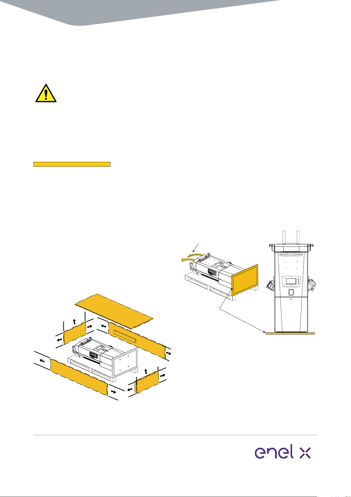
Do not work under suspended loads.
Two people may be required as the unit
may swing.
DOCUMENT KEY:
Items shown in orange are parts that
require action for that step.
1. Open crate
Move the crate as close to the
prepared installation site as possible.
Ensure there is enough room to
maneuver the lifting apparatus.
Remove/slide out all crate tubes to
disassemble the cardboard crate.
2. Lift JuicePump user unit
to vertical
Securely attach the lifting straps at the
top of JuicePump to the lifting apparatus
and gently raise to a standing position on
the shipping baseplate.
NOTE: The JuicePump user unit is
2,060 mm / 81.102 inches tall on the
shipping baseplate.
Once the unit is upright remove all wrap-
ping. Ensure the connection to the lifting
apparatus is secure at all times.
Shipping
Baseplate
Lifting Straps
Unpacking

10 www.enelx.com
Phone: +1-844-584-2329
TRI125.INS.036.3
3. Remove shipping bolts
Unscrew the 4 bolts from the shipping
module not shown).
4. Secure to foundation
Lift the JuicePump user unit and place
over the prepared foundation. Feed the
conduit and wiring through the power in
points (fasteners not supplied).
Note: Use the plastic inserts in the holes
of the baseplate.
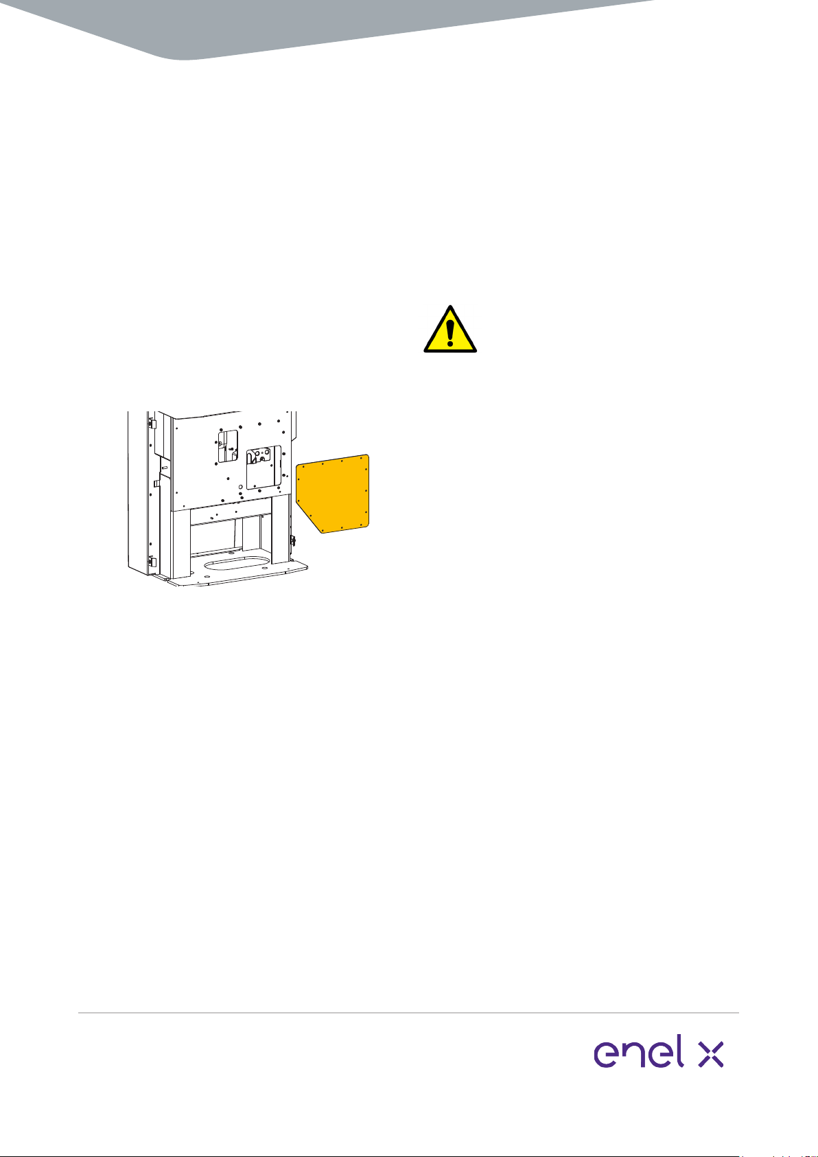
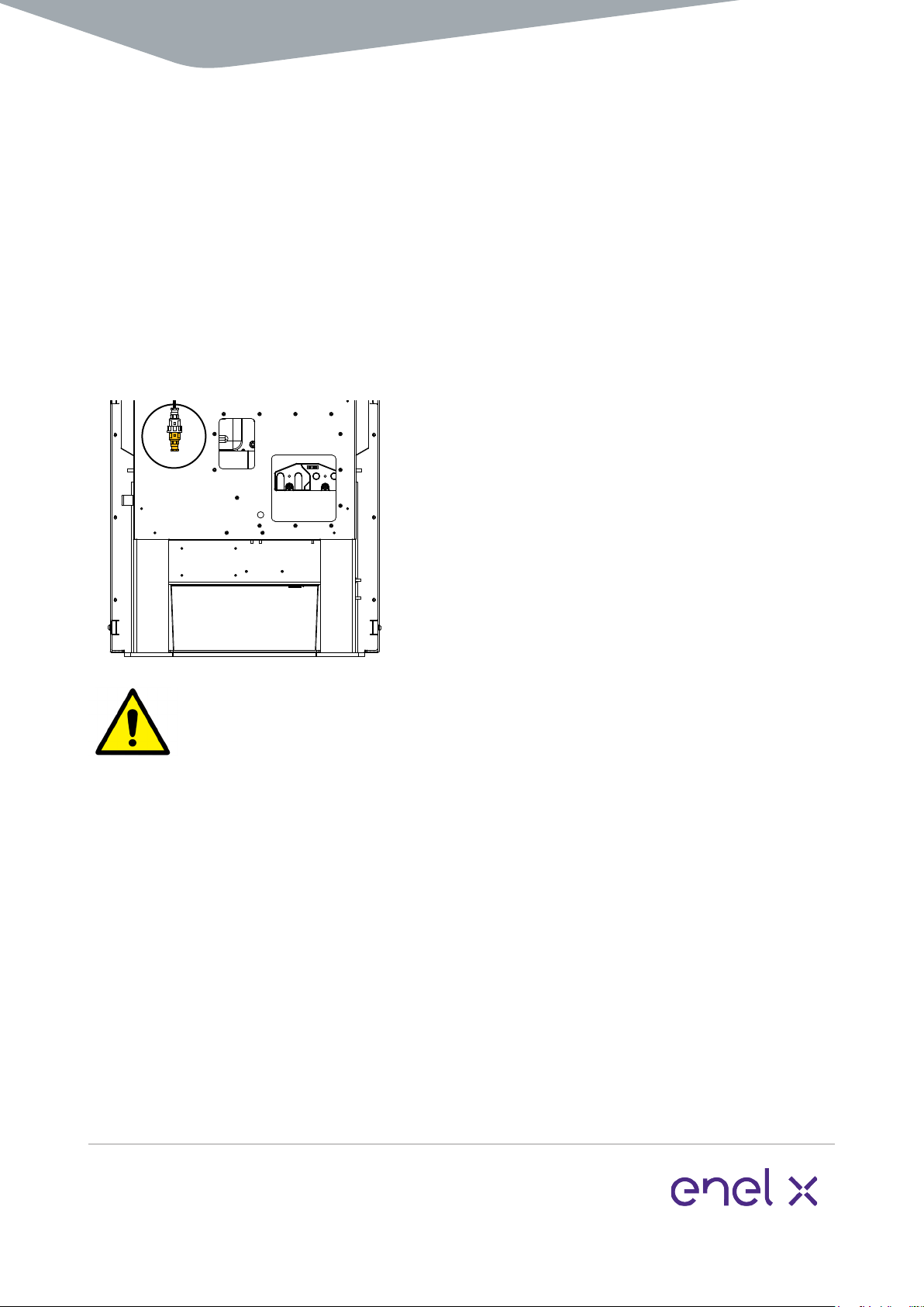
1. Remove lower front panel
4 security screws (2 per side) from the
front panel, then remove them. Pull the
front panel forward to remove and safely
store all parts.
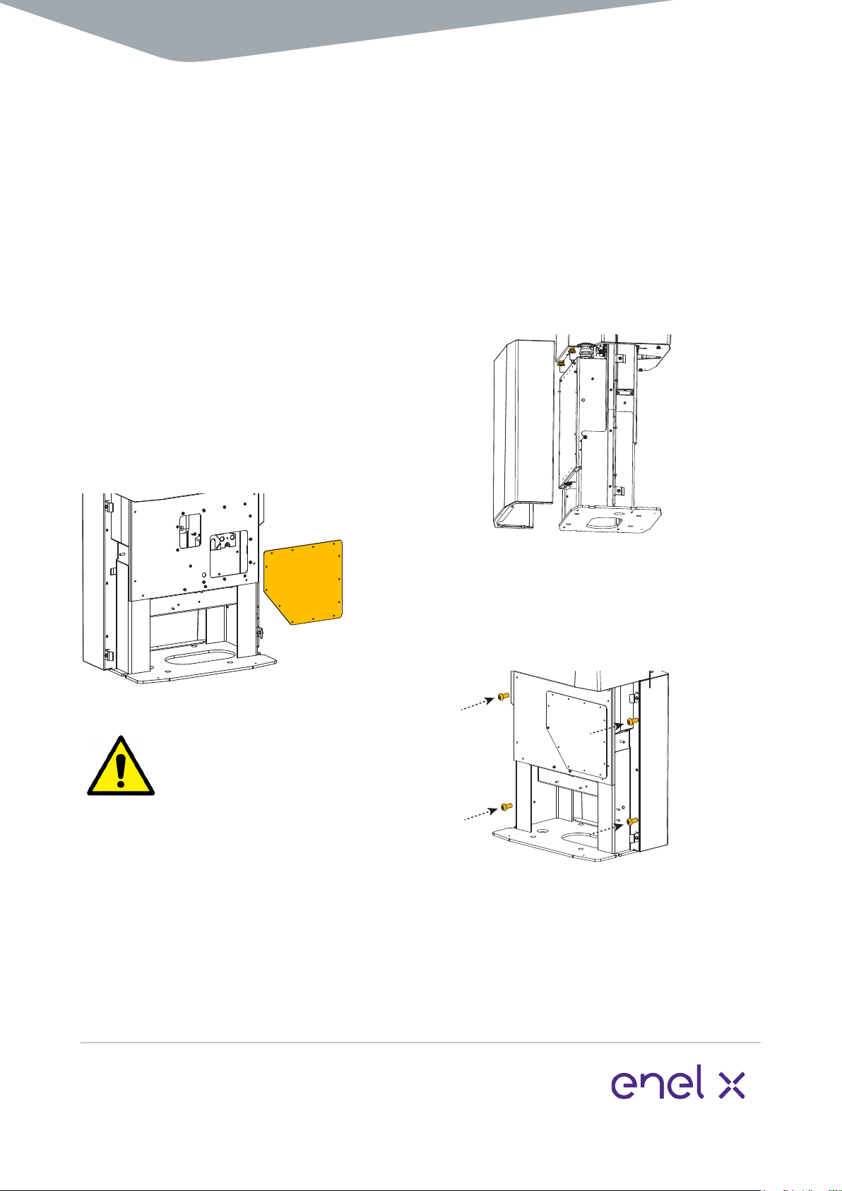
2. Remove rear lower panel
Follow this step to increase visibility and
access to the mounting holes. If visibility
Use the 4 mm Allen key to unscrew the 4
screws that attach the rear panel to the
enclosure and slide out to remove.
Installation
11 www.enelx.com
Phone: +1-844-584-2329
TRI125.INS.036.3
8. Remove M10 fasteners
fasteners. Remove the fasteners ready for
wiring in.
\
CAUTION
correctly into the cable gland.
Ensure the cable is sitting correctly in the
gland and tighten to ensure no water or
debris can enter. If in doubt, use an
appropriate outdoor-rated sealant.
When the cable gland has been tightened,
pull on the cable to ensure it doesn’t slip.
Remove the enclosure access cover
screws with the 4 mm allen key to pre-
pare the JuicePump for wiring installation.
The enclosure access cover has an
attached gasket. Ensure this is carefully
stored to avoid damage or accumulation
of debris.
6. Remove tape and attach
cable glands
7. Prepare wiring
Fit the individual power cabling into
each M32 cable gland, ensuring there is
enough length to add the M10 lugs (not
supplied) and attach to the busbars. Fit
each wire with an M10 lug.
Installation

12 www.enelx.com
Phone: +1-844-584-2329
TRI125.INS.036.3
Wiring & commissioning
Note: Refer to the TRI125.INS.018
JuicePump RT 175-S Site Installation
Manual for a table of all torques used
during installation.
M8 grounding stud (M8 lug not
supplied) on the inside channel.
CAUTION
Wiring and commissioning of the charger
personnel only.
The wiring diagram is also available on
the inside of the Service Hatch.
1. DC conductors
Attach the M10 lugs onto the negative
and positive busbar positions as shown.
Ensure that the lugs and connection
points are clean and free of dirt before
you make the connections.
CRITICAL
Clean the surface areas of the
mating surfaces with an abrasive pad and
use jointing compound between the
mating surfaces.
You must use a torque wrench to tighten
you must apply a torque mark to the
stud and nut.
CRITICAL
Tightening Torque:
30 Nm / 22 lb-ft
13 www.enelx.com
Phone: +1-844-584-2329
TRI125.INS.036.3
Wiring & commissioning
Note:
connections, refer to the wiring diagram
sticker on the inside of the Service Hatch.
2. Single phase power
terminals are located on the underside of
the top-left section of the wiring access
hatch. Refer to the wiring diagram on the
inside of the Service Hatch, or wire into
the terminal blocks as follows:
12
Terminal blocks
3 4
1: Line
2: Neutral
4: Earth reference
Strip and crimp the single-phase wires
before terminating to the appropriate
terminals. Once installed, perform a
pull-test to ensure that the terminations
are secure.
CRITICAL
If the single-phase wiring is run in a
three-core cable (2C+E), do not
terminate the third core (earth) to the
common grounding terminal (green and
yellow). This wire must be terminated to
terminal block 4.
If not installed correctly, it will prevent
the IMI from adequately monitoring the
site earth.
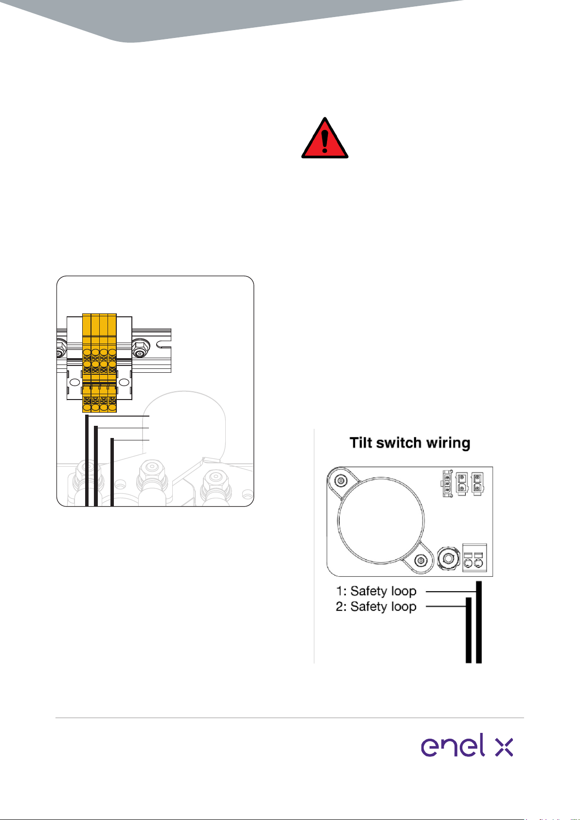
3. Safety loop
The two safety loop terminals are
located on the tilt-switch PCB, located
on the bottom-right section of the wiring
critical for these wires.
14 www.enelx.com
Phone: +1-844-584-2329
TRI125.INS.036.3
The Ethernet port is situated on the front
Twist to disengage the base cap and wire
in the Category 6a STP Ethernet cable.
CAUTION
To ensure the stability of communication
to the user unit, it is important that when
terminating the network cable, the shield
is earthed appropriately to the terminal.
Ethernet port access

www.enelx.com
Phone: +1-844-584-2329
TRI125.INS.036.3
Fiber optic access
interface module is required.
shall be mounted at the bottom of the
user unit.
into the Ethernet port of the user unit.
Ensure that the coupling ring is tight,
connected, the connection is tight.
For detailed wiring instructions, see
-
ing and Cabling
.
16 www.enelx.com
Phone: +1-844-584-2329
TRI125.INS.036.3
Follow these steps in order to ready
the unit for commissioning:
1. Remove lifting straps
Carefully remove the lifting straps from
the top slots in the plastic.
2. Attach enclosure access cover
Check to make sure the gasket has not
been damaged or soiled. Use the 4 mm
Allen key to attach the enclosure access
cover screws.
CAUTION
If using a power drill to fasten the nuts,
ensure the correct torque setting of no
greater than 2.0 Nm / 17.7 lb-inch. If
using a hand tool, fasten until resistance
is felt. Do not over-tighten.
Over-tightening may result in damage to
the screws and/or gasket, reducing the
compromise the ingress protection rating
of the enclosure.
3. Attach the rear lower panel
Lift the panel and slide it over the
both sides until it is secure under the top
screws on both sides.
Do not over-tighten.
Closing checklist

17 www.enelx.com
Phone: +1-844-584-2329
TRI125.INS.036.3
4. Plug in the parking sensor
The JuicePump user unit has a parking
sensor available for use on the front lower
panel.
Unclip the parking sensor plug from
the front metal panel and plug into the
parking sensor.
Note that the plug for the parking sensor
is located inside and under the central
edge of the front panel.
Screw the plugs together to ensure the
Raise and slide the front lower panel into
panel.
Fasten both sides with nylon washers and
tool.
Do not over-tighten.
The JuicePump is now ready for
commissioning.
Closing checklist
Other manuals for JuicePump
4
Table of contents
Other Enel X Automobile Accessories manuals


Popular Automobile Accessories manuals by other brands

Go groove
Go groove SMARTmini AUX operating manual

Air Design
Air Design SILVERADO 2014 + installation manual

Sony Ericsson
Sony Ericsson HCB-150 manual

U.S. General
U.S. General 6"OFF ROAD LIGHT 95811 Assembly and operation instructions

FormFit
FormFit HDW 9J 04 manual

MetaSystem
MetaSystem T.30 installation manual


